Creating a Layout, Section and Elevation with dimensions using AutoCad
AIM: The aim of this assignment is to produce the drawings of plan , sectional elevation and side elevation of the plan.
The aim of the first question was to draw the plan of the house.
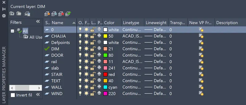
INTRODUCTION: Any architectural drawing needs to be detailed properly, the deatails include, the room sizes their location, the wall thickness, the windows , doors sizes. The thickness of the walls. To distinguish and to easily understand the details the layer command is used. every detail, walls, windows, doors, chajjas, stairs etc were given different colors the following picture shows the number of layers used.
PROCEDUR:
Step 1:
The different layers are created and assigned to each feature,
example new layer was picked, named as chajja, then color of the line, the chajja line is picked as ACAD ISO dash.
similrly other names were given and different colors anf lines were choosen.
Step 2:
keeping the wall layer as current layer
Xline command.
the xline command was used to draw the construction lines parallel to represent the walls at different location.
Offset command.
using offset command the wall thickness were choose as 250 and differet room sizes were drawn
Fillet command,
Using fillet command corners of the rooms were arrived by keeping radius as zero.
The drawing was started at the top left corner and finished at the bottom.
Step -3
THe different window and door schedule was choosen,
The schedule was drawn using the table command.
Step-4
keeping the door layer as current layer
The different location of door was done.
Using ARC command, the start center end command the door was drawn and
JOin command was used to join the polyline and arc. This was used to draw different door sizes.
Using mirror command, rotate command the doors were copied at the required location.
Step-5
keeping the window layer as current layer
The windows were drawn at tfifferent location using offset and polyline command.
Step 6
keeping the stair layer as current layer
The staircase was drawn using offset command.
Step 7
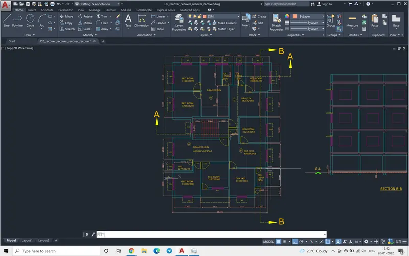
QL command was used to draw the section A-A as shown in the figure.
Step 8:
Using dimension linear command the different levels were measured and annotated.
Step 9:
Mtext command different room dimensions and other notes were written.
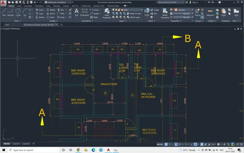
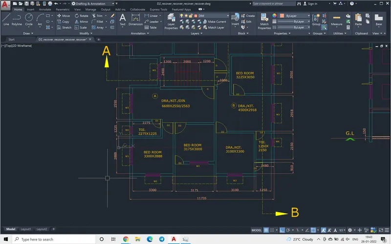
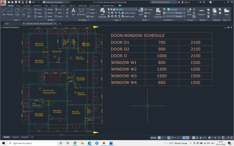
@@@@@@@@@@@@@@@@@@@@@@@@@@@@@@@@@@@@@@@@@@@@@@@@@@@@@@@
@@@@@@@@@@@@@@@@@@@@@@@@@@@@@@@@@@@@@@@@@@@@@@@@@@@@2@@
@@@@@@@@@@@@@@@@@@@@@@@@@@@@@@@@@@@@@@@@@@@@@@@@@@@@@@@
@@@@@@@@@@@@@@@@@@@@@@@@@@@@@@@@@@@@@@@@@@@@@@@@@@@@@@@@@@@@@@@@@@@@
@@@@@@@@@@@@@@@@@@@@@@@@@@@@@@@@@@@@@@@@@@@@@@@@@@@@@@@@@@@@@
@@@@@@@@@@@@@@@@@@@@@@@@@@@@@@@@@@@@@@@@@@@@@@@@@@@@@@@
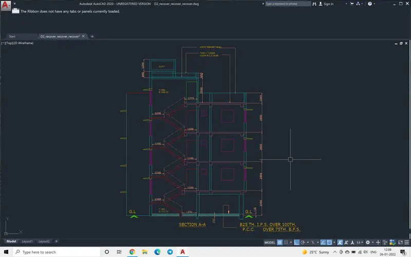
AIM: THe aim of the second question was to draw the elevation of section A-A.
The section is taken through the stairs and towars the top right corner of the building through the toilet and the bedroom.
INtroduction:- The ground floor level the ground slab below details were also shown. The ground floor height is different from the remaining foor. the ground floor to first floor thr stair details vary compared tot the other floors. THe headroom and the overhead tanks were also shown. The midlanding and the floorlevel landings are also shown in the drawing. at the floor level landing door is given.
Procedure.
Step 1:
From the plan drawn using xline command the view was projected.
Later the ground floor details of pcc thickness and other details were drawn.
Step 2:
Using offset command the different floor levels were marked.
Step3:
Using the polyline command the beam drawing with the slab were drawn together. as it is drawn using polyline, the beams and the slab would be acting like single entity when selected. Once this is finished, it is selected and copied at different floor locations using copy command.
Step 4:
The walls at the toilet and the bedroom location as well as at the stair location was done keeping the wall layer as current layer.
Step 5:
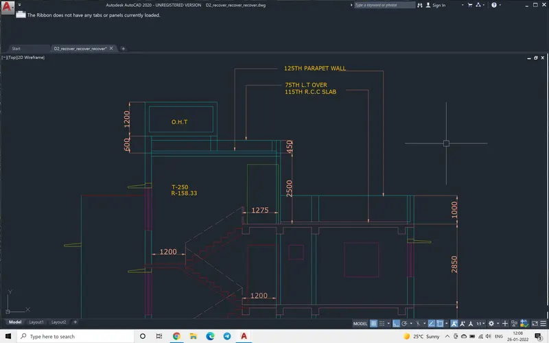
The parapet walls and the over head tank sizes were drawn using polyline command.
Step 5: The windows and the chajjas were located using copy command.
Step 6:
The staircase layer was kept as current layer and one tread,T-250 and rise R=143.75 was drawn. Using copy command this step was repeatedly copied till the midlanding. then midlanding was completed. The above procedure is repeated and stairs were drawn till first floor. The railing height was taken as 600 and is drawn as shown, The layers used in both first and secong questions are repeated.
The staircase layer was kept as current layer and one tread,T-250 and rise R=158.33 was drawn. Using copy command this step was repeatedly copied till the midlanding. then midlanding was completed. The above procedure is repeated and stairs were drawn till second floor. The railing height was taken as 600 and is drawn as shown. The remaining floors this is repeated.
Step 7:
THe door at the floor level landings were drawn.
Step 8:
Using dimension linear command the different levels were measured and annotated.
Step 9:
Mtext command different room dimensions and other notes were written.
The following drawing is achieved.

@@@@@@@@@@@@@@@@@@@@@@@@@@@@@@@@@@@@@@@@@@@@@@@@@@@@@@@@@@@@@@
@@@@@@@@@@@@@@@@@@@@@@@@@@@@@@@@@@@@@@@@@@@@@@@@@@@@@@@@@@@@@@@
@@@@@@@@@@@@@@@@@@@@@@@@@@@@@@@@@@@@@@@@@@@@@@@@@@@@@@@@@@@@@
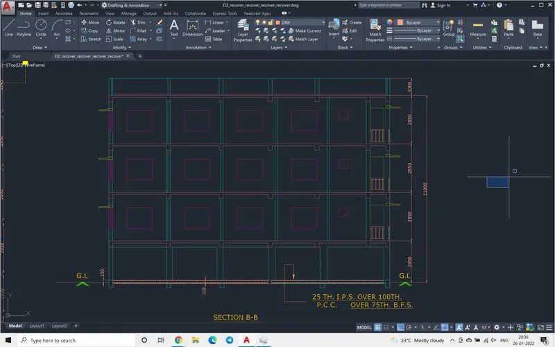
AIM: THe aim of the third question was to draw the elevation of section B-B.
The section is taken through the right side of the building through the the bedrooms and the right-lower toilet.
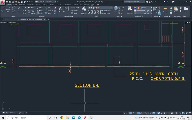
INtroduction:- The ground floor level the ground slab below details were also shown. The ground floor height is different from the remaining foor. the ground floor to first floor thr stair details vary compared tot the other floors.
Procedure.
Step 1:
From the plan drawn using xline command the view was projected.
Later the ground floor details of pcc thickness and other details were drawn.
Step 2:
Using offset command the different floor levels were marked.
Step3:
Using the polyline command the beam drawing with the slab were drawn together. as it is drawn using polyline, the beams and the slab would be acting like single entity when selected. Once this is finished, it is selected and copied at different floor locations using copy command.
Step 4:
The walls are drawn at each floor level and the windows were located.
Step 5:
The parapet wall was drawn above the last floor.
Step 5: The windows and the chajjas were located using copy command. The hand railing were drawn at the right end of the each floor using polyline command and copy command.
Step 6:
Using dimension linear command the different levels were measured and annotated.
Step 7:
Mtext command different room dimensions and other notes were written.
The following drawing is achieved.