Week 3 - Pitot tube
Pitot static tube
Aim:
- Explain about pitot-static tube and also establish a relationship between Total (stagnation) pressure and static pressure.
- Perform a steady state simulation to calculate the Velocity change along the domain and find the percentage from the given data.
- Post process and plot the necessary contours and justify the results.
Theory:
Pitot tube :
A pitot tube, also known as a pitot probe, is a flow measurement device used to measure fluid flow velocity. The pitot tube was invented by the French engineer Henri Pitot in the early 18th century and was modified to its modern form in the mid-19th century by French scientist Henry Darcy. Pressure measurement is used for other readings for the pilot namely in altimeter and airspeed Measurement.
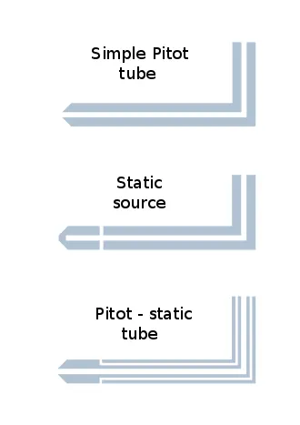
Pitot tubes are used for fluid flow measurement to find the velocity of the boat in water, the velocity of aircraft, and the velocity of gases in industries. Pitot tubes actually measure the pressure that is used in calculating the velocity of the fluid or body. Pitot tubes will not calculate the velocity directly. There are commonly three types of pitot tubes.
- Simple pitot tube: Measures the total pressure of the incoming fluid
- Static tube: Measures the static pressure of the incoming fluid
- Pitot static tube:
- Measures the total pressure and the static pressure. It will be used in low-speed aircraft's Measurement will be accurate in the low Mach conditions (Incompressible Flow).
- The construction of the pitot-static tube is different from the other two tubes. It is the combination of the Features of the other two tubes.
- It has an opening at the center that runs through the tube. This opening is used to measure the total pressure of the incoming fluid.
- It also has two openings on the sides and runs through the tube without any contact with the other opening. This is used to measure the static pressure of the incoming air.
Theory of operation
- The basic pitot tube consists of a tube pointing directly into the fluid flow. As this tube contains fluid, a pressure can be measured;
- The moving fluid is brought to rest (stagnates) as there is no outlet to allow flow to continue.
- This pressure is the stagnation pressure of the fluid, also known as the total pressure or (particularly in aviation) the pitot pressure.
- The measured stagnation pressure cannot itself be used to determine the fluid flow velocity (airspeed in aviation). However, Bernoulli's Equation states:
Difference in Static and Total Pressure
Since the outside holes are perpendicular to the flow of air, these tubes are pressurized by the local random component of the air velocity. The pressure in these tubes is the static pressure.
The center tube, however, is pointed in the direction of travel and is pressurized by both the random and the ordered air velocity.
The pressure in this tube is the total pressure discussed in Bernoulli's equation. The pressure transducer measures the difference in total and static pressure.
measurement = pt - ps
Stagnation pressure = static pressure + dynamic pressure (the equations are shown in below picture)
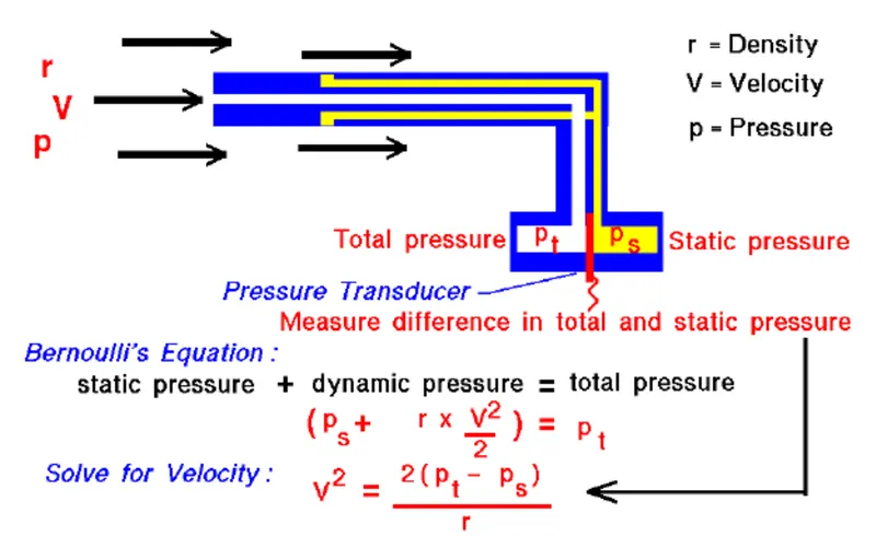
The relation between the Static pressure Total pressure and the velocity of the fluid
With the difference in pressures measured and knowing the local value of air density (r) from pressure and temperature measurements, we can use Bernoulli's equation to give us the velocity.
Bernoulli's equation states that the static pressure plus one-half the density times the velocity (V) squared is equal to the total pressure
Ps + [ (1/2) ⋅ r ⋅ (V^2) ] = Pt
Solving for V:
V^2= [2 ⋅(Pt-Ps) ] / r
NOTE: The above equation applies only to fluids that can be treated as incompressible. Liquids are treated as incompressible under almost all conditions. Gases under certain conditions can be approximated as incompressible.
Given Inputs in problem:
|
Velocity (m/s) |
Gauge Pressure (Pa) |
|
240 |
-2817 |
|
100 |
33287 |
|
62 |
67580 |
Procedure:
The methodology of the simulation is as follows:
- Geometry creation in Ansys space claim
- Mesh generation
- Fluent set up
- Post processing in CFD post
1) Geometry :
- By opening Ansys space claim, The pitot-static tube is created.
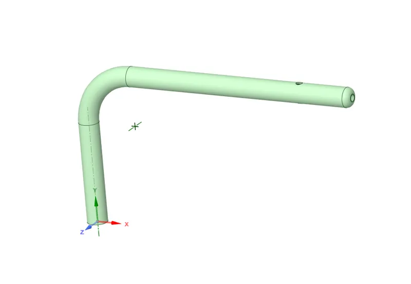
- Then the enclosure is made without extracting fluid volume.
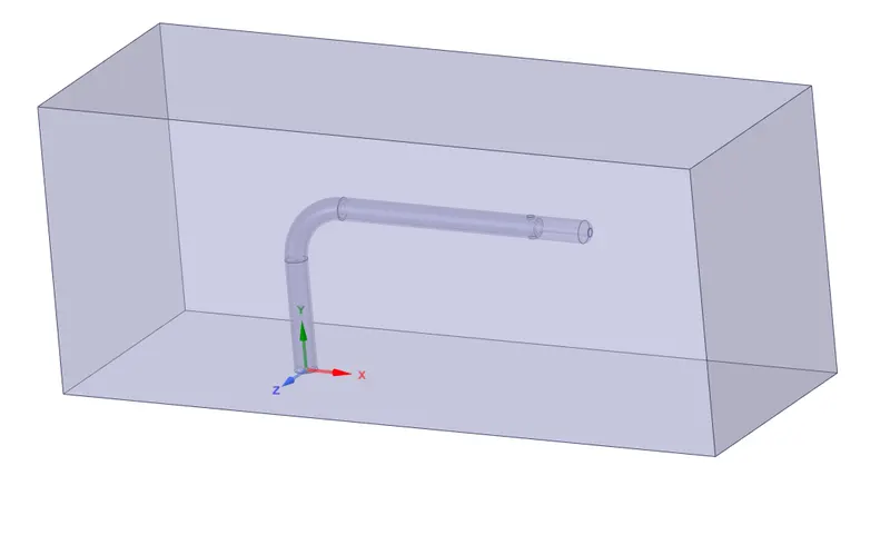
2) Mesh generation:
- The geometry is saved and transferred to ansys mesher for the mesh generation.
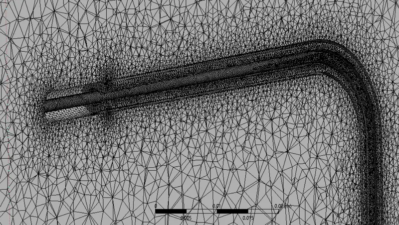
- With following mesh settings
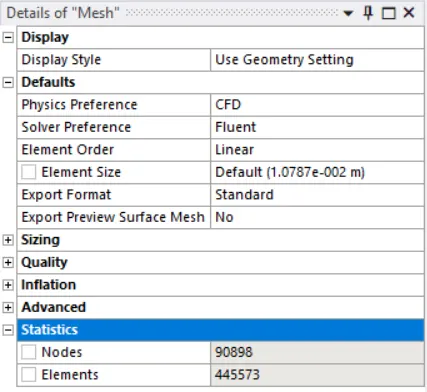
- And following named sections

3) Fluent set up:
- Operating conditions:
In this section , the reference pressure is set to zero. This is because only absolute pressure is considered in the simulation.
- Material selection:
Ansys fluent offers a wide variety of materials for the users to choose from. In this case, air with following properties is used.
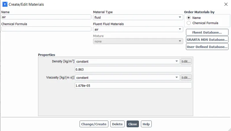
- Physics set up:
- Energy is turned off, since we need to deal with only pressure change in the simulation.
- Laminar flow is assumed and selected.
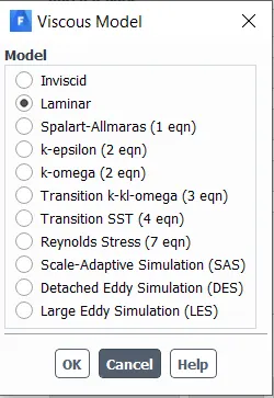
- General settings:
- Pressure based solver is used.
- With absolute velocity formulation.
- Steady state analysis.
- Gravitation is not turned on, since the flow is horizontal.
- Boundary conditions:
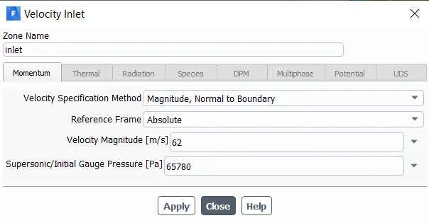
Inlet:
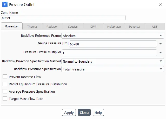
Outlet:
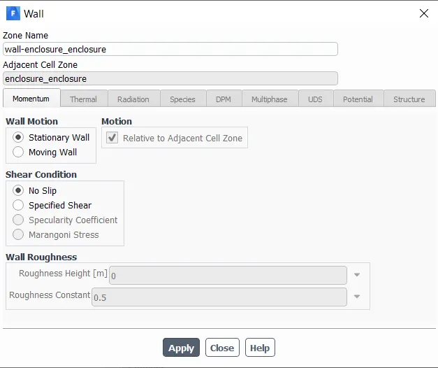
Wall:
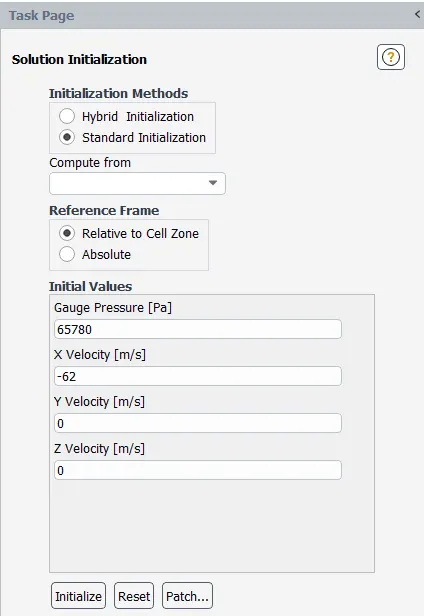
- Initialization:
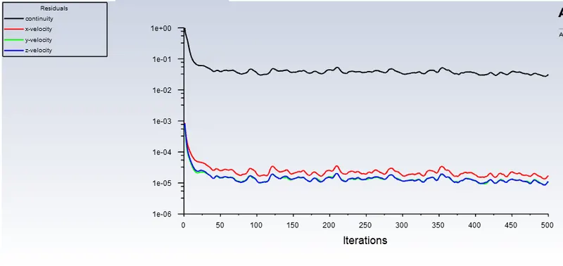
The convergence criterion is set to 1e-03
FMG initialization is done

- Reference conditions:
For the reference condition, the flow parameters are calculated from inlet.
- Contours and surface reports:
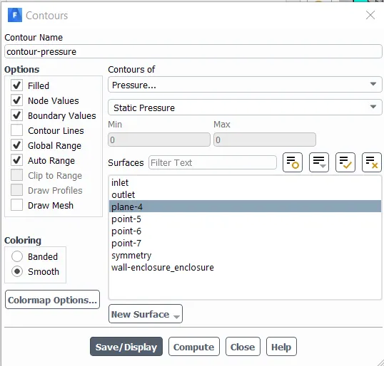
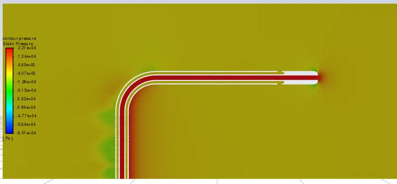
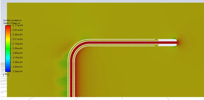
1.Contours of Total and Static pressure is made on a X-Y plane,
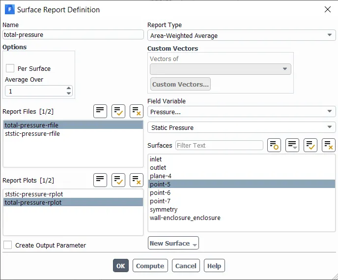
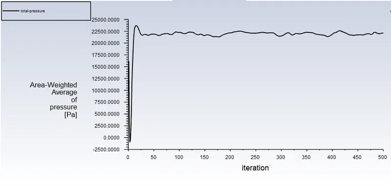
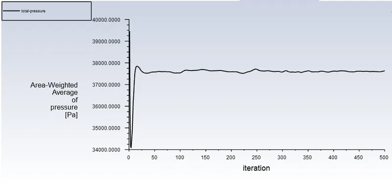
2. Surface report of area weighted average of total pressure is made on point-5
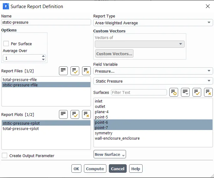
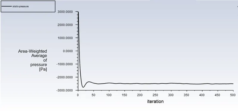
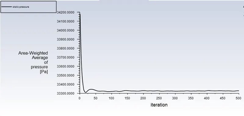
3. And Surface report of area weighted average of static pressure is made on point-6 and point-7
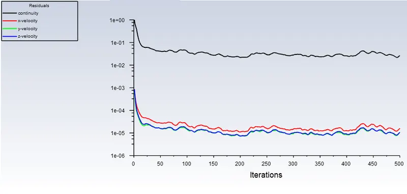
The simulation is run for 500 iterations
Solution:
Case-1 : Ve= 240m/s ; pressure= -2817 Pa
Residuals:
Pressure contour:
Total Pressure:
Static Pressure:
Validation and error percentage:
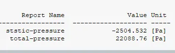
Velocity Vth= {[2 ⋅(Pt-Ps) ] / r}^(1/2) = 238.72 m/s
error(1) = 100% - [Vth/Ve X 100]% = 0.5%
Case-2 : Ve= 100m/s ; pressure= 33287 Pa
Residuals:
Pressure contour:
Total Pressure:
Static Pressure:
Validation and error percentage:
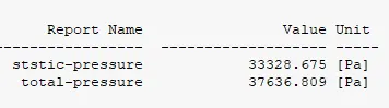
Velocity Vth= {[2 ⋅(Pt-Ps) ] / r}^(1/2) = 99.92 m/s
error(2) = 100% - [Vth/Ve X 100]% =0.08%
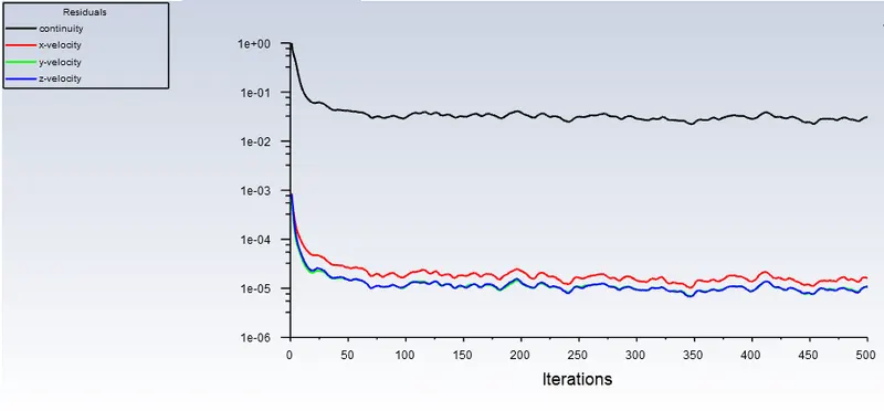
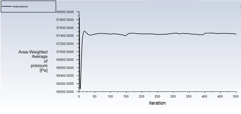
Case-3 : vel= 62m/s ; pressure= 65780 Pa
Residuals:
Pressure contour:
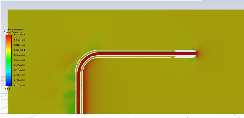
Total Pressure:
Static Pressure:
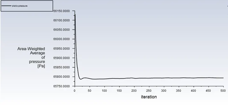
Validation and error percentage:
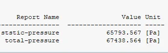
Velocity Vth= {[2 ⋅(Pt-Ps) ] / r}^(1/2) = 61.71 m/s
error(3) = 100% - [Vth/Ve X 100]% = 0.41%
Average Error:
Error(avg) = 0.33%
Conclusion:
The comparison of the actual and analytical results of velocity is performed by calculating the error and the error is around 0.33% which is acceptable for this kind of simulation.