Week 10 - Simulating Combustion of Natural Gas.
Aim:
- To perform a combustion simulation on the combustor model at different fuel-water ratio at fuel inlet.
- Plot the variation of the mass fraction of the different species in the simulation as well as track NOx and soot formation.
Theory:
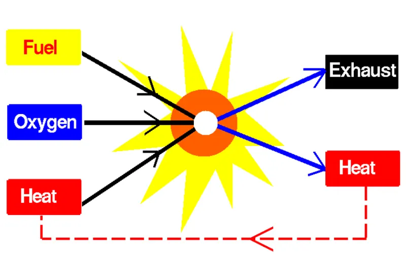
Combustion
Combustion is a high-temperature exothermic redox chemical reaction between a fuel and an oxidant, usually atmospheric oxygen. When the fuel and air react, it releases heat and light energy. This heat and light energy results in the flame. Once the reaction takes place between the fuel and oxygen it will produce flames, heat and unburnt gases.
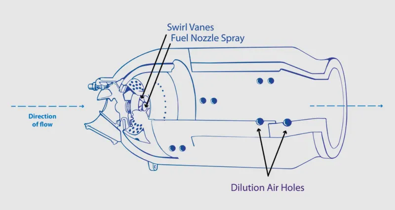
Combustor
A combustor is an area or a chamber where the combustion takes place. It can be a burner, combustion chamber, or flame holder. In a combustor, the high-pressure air is fed which is heated at constant pressure and is guided to the turbines through the nozzle-guided vanes.
A combustor must maintain stable combustion despite the velocity of the air is on the higher side. In order to do so the air mixes and ignites the fuel and to complete the combustion more air is added. The typical components of the combustor include fuel inlet, air inlet, and the walls of the combustor. The drawbacks of the combustor model include the emission of species such as carbon-di-oxide and emission of NOx and soot formation due to incomplete combustion which is harmful to the environment. The temperature plot should be uniform, if it is not then it will lead to temperature hotspots leading to the thermal damage of the combustor.
Emissions
Uncatalyzed combustion in air requires relatively high temperatures. Complete combustion is stoichiometric concerning the fuel, where there is no remaining fuel, and ideally, no residual oxidant. Thermodynamically, the chemical equilibrium of combustion in air is overwhelmingly on the side of the products. However, complete combustion is almost impossible to achieve, since the chemical equilibrium is not necessarily reached, or may contain unburnt products such as carbon monoxide, hydrogen and even carbon (soot or ash). Thus, the produced smoke is usually toxic and contains unburned or partially oxidized products. Any combustion at high temperatures in atmospheric air, which is 78 percent nitrogen, will also create small amounts of several nitrogen oxides, commonly referred to as NOx, since the combustion of nitrogen is thermodynamically favoured at high, but not low temperatures. Since burning is rarely clean, fuel gas cleaning or catalytic converters may be required by law.
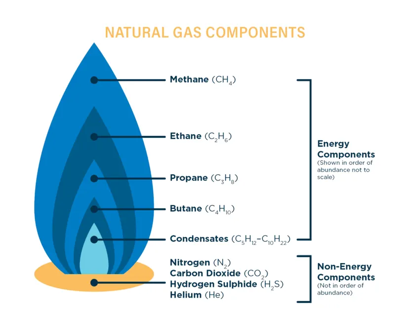
Natural gas
Natural gas is the cleanest of all the fossil fuels, as evidenced in the Environmental Protection Agency Composed primarily of methane. The main products of the combustion of natural gas are carbon dioxide and water vapor, the same compounds we exhale when we breathe.
Coal and oil are composed of much more complex molecules, with a higher carbon ratio and higher nitrogen and sulfur contents. This means that when combusted, coal and oil release higher levels of harmful emissions, including a higher ratio of carbon emissions, nitrogen oxides (NOx), and sulfur dioxide (SO2)
The combustion of natural gas, on the other hand, releases very small amounts of sulfur dioxide and nitrogen oxides, virtually no ash or particulate matter, and lower levels of carbon dioxide, carbon monoxide, and other reactive hydrocarbons.
Natural gas, emitting fewer harmful chemicals into the atmosphere than other fossil fuels, can help to mitigate some of these environmental issues. These issues include:
- Greenhouse Gas Emissions
- Smog, Air Quality, and Acid Rain
- Industrial and Electric Generation Emissions
- Pollution from the Transportation Sector – Natural Gas Vehicles
Applications of combustion
The typical application of the combustion includes
- Burning of wood or coal for household purposes.
- Burning of petrol or diesel for using vehicles like the car, planes, ships, jets, rockets, etc.
- Cooking purposes.
- For the production of energy in thermal power plants.
Mass Fraction
The ratio of the mass of a component in a mixture to the total mass of the mixture is known as mass fraction.
Mole Fraction
The ratio of a number of molecules of one component of solution or other mixture to the total number of moles representing all of the components.
Procedure:
Geometry
- The geometry is loaded into the Spaceclaim.
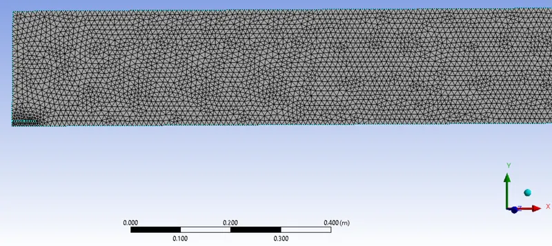
- The combustor is modeled into a 2-d axisymmetric shape. The academic license restricts the use of computational cells, making it difficult for the entire geometry to be taken for simulation.
- The geometry consists of a small fuel inlet and a larger air outlet.
Mesh
- Setting the element size as 0.007 m
- keep the capture proximity on and mesh method as triangular.
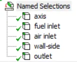
- Assign the named selections appropriately.
Solver
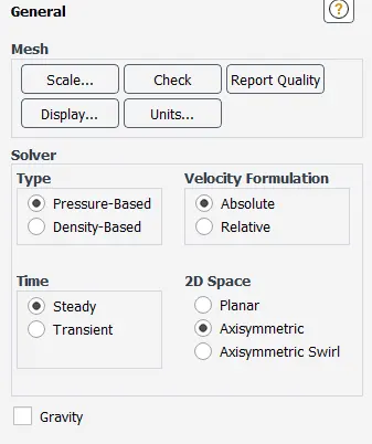
- General settings
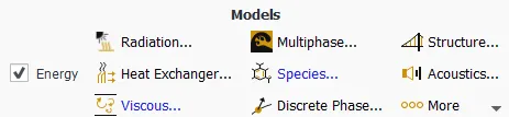
- Model settings
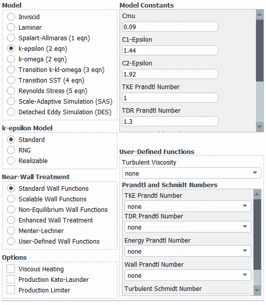
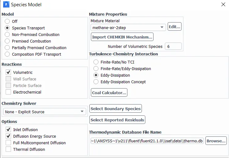
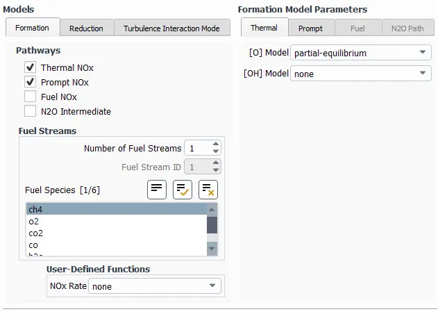
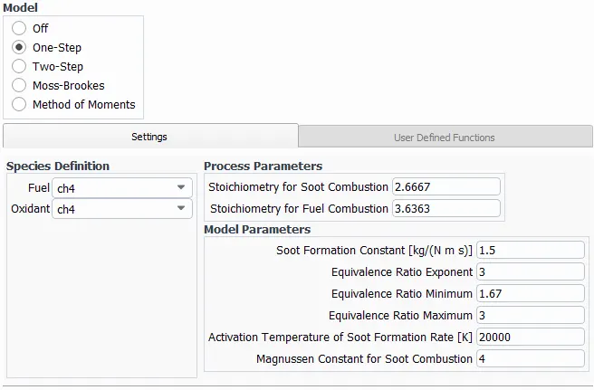
- Boundary settings
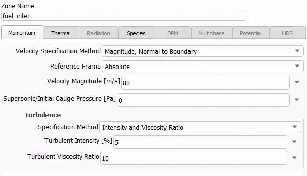
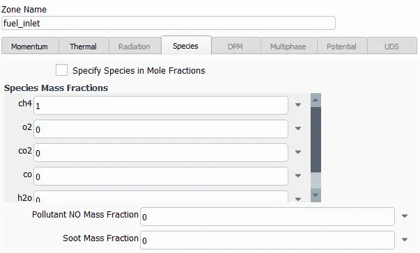
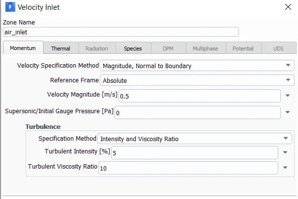
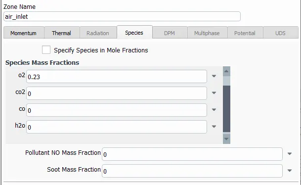
- Initialization settings

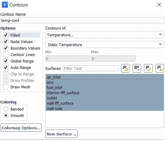
- Contour settings
Post-process
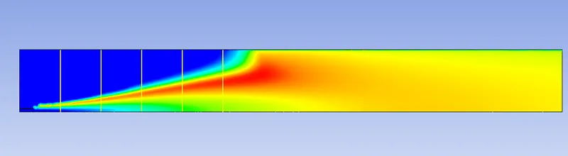
- apply contour for each element who's mass fraction needs to be monitored along with one temperature contour.
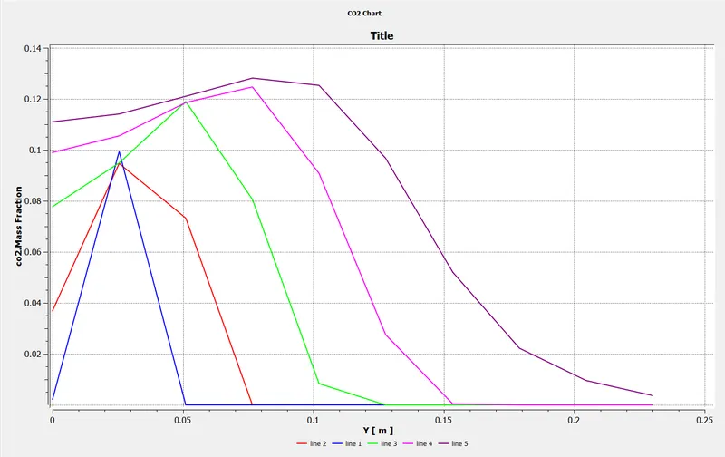
- insert 5 lines for motitoring the elements' mass fraction.
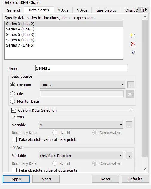
- plot the curves for mass fraction by inserting the chart as follows and selecting desired data that needs monitoring.
Observation:
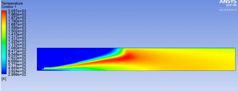
Case -1, no water in fuel inlet.
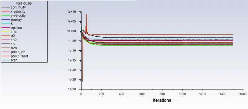
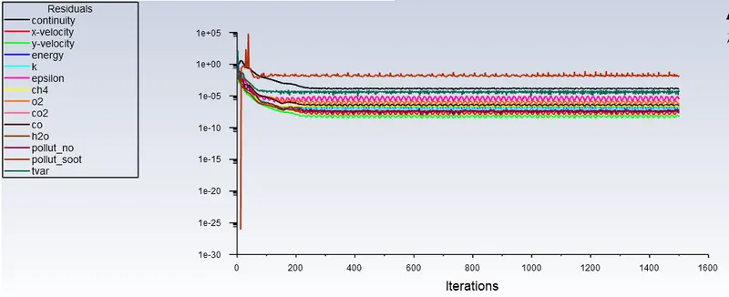
Residual
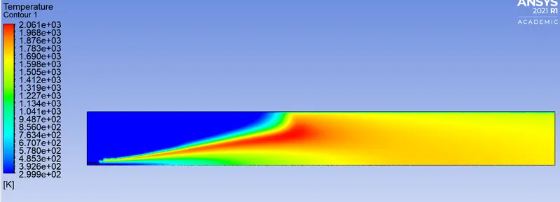
Temperature Contour
Mass Fraction
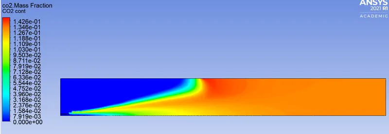
CO2
Mass Fraction Contour
plot
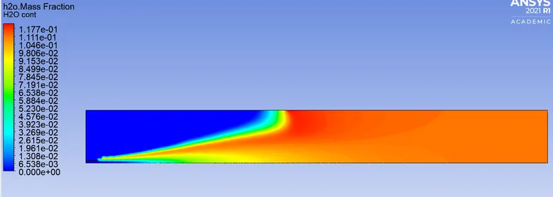
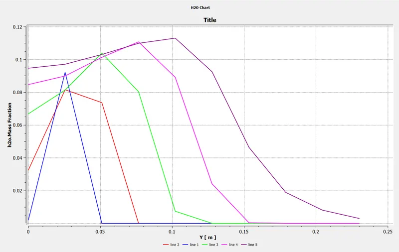
H2O
Mass Fraction Contour
plot
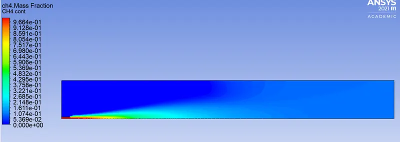
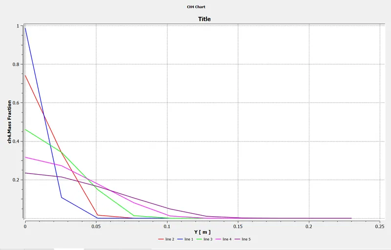
CH4
Mass Fraction Contour
plot
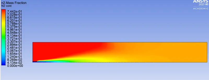
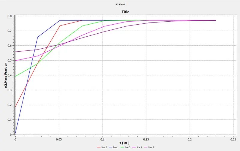
N2
Mass Fraction Contour
plot
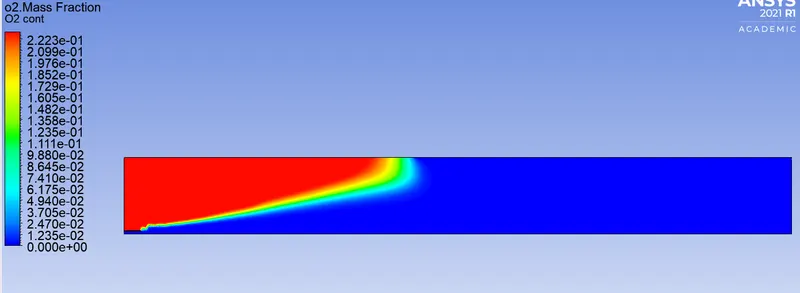
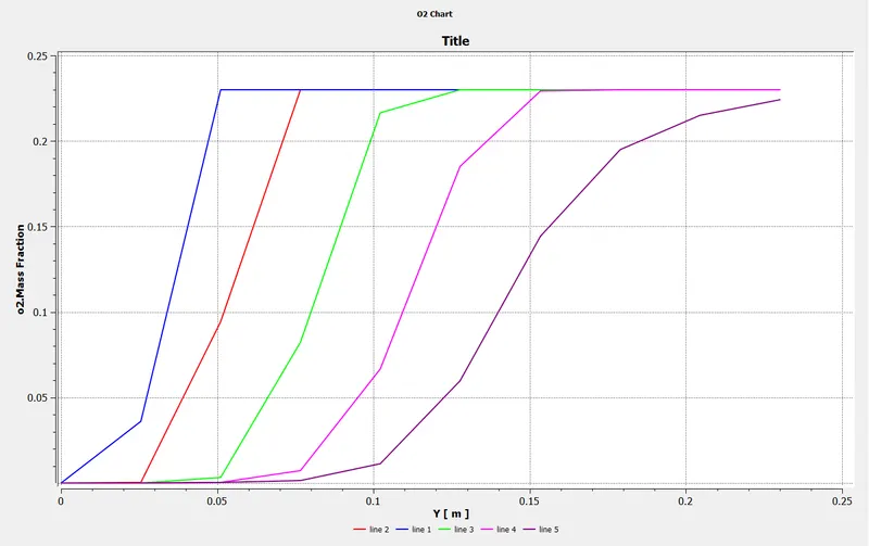
O2
Mass Fraction Contour
plot
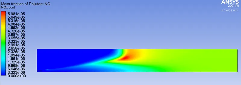
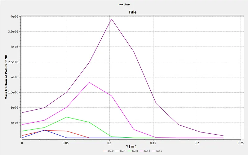
NOx emissions
Mass Fraction Contour
plot
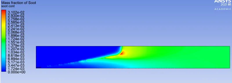
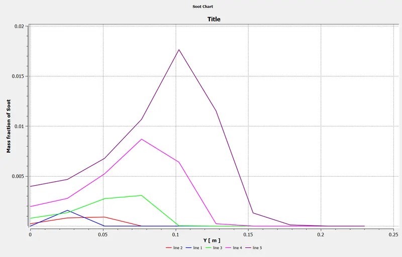
Soot formation
Mass Fraction Contour
plot
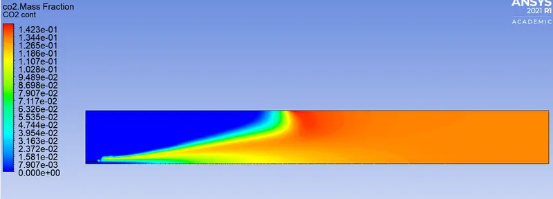
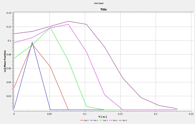
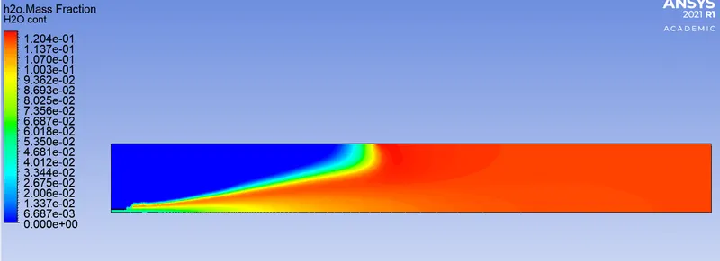
Case -2, 5% water in fuel inlet.
Residual
Temperature Contour
Mass Fraction
CO2
Mass Fraction Contour
plot
H2O
Mass Fraction Contour
plot
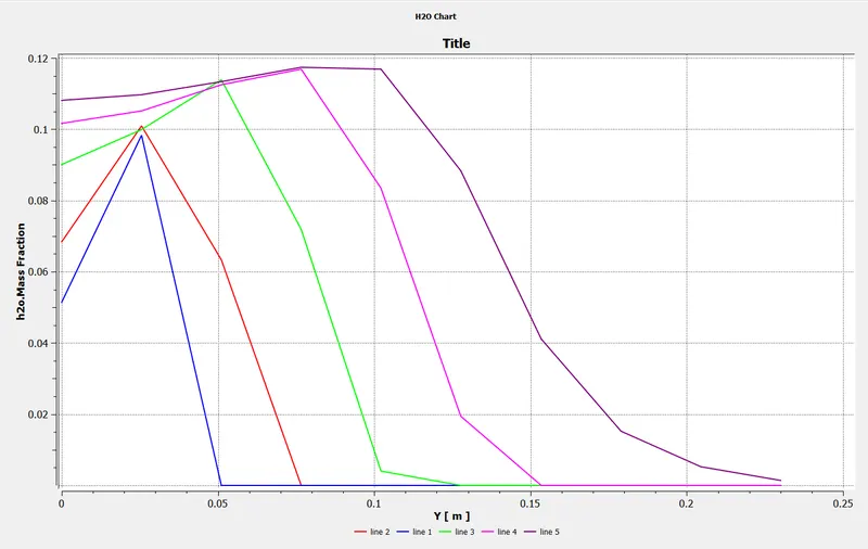
CH4
Mass Fraction Contour
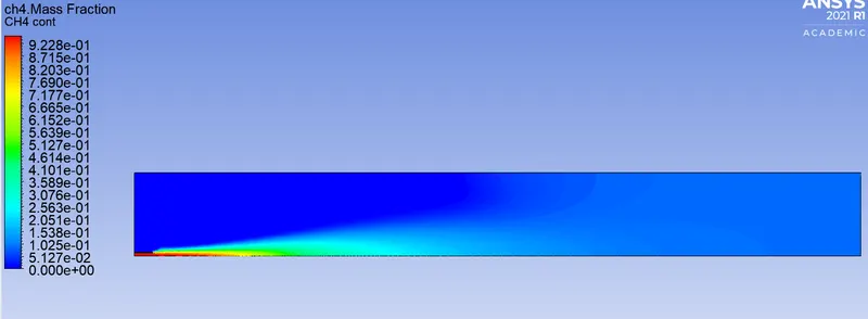
plot
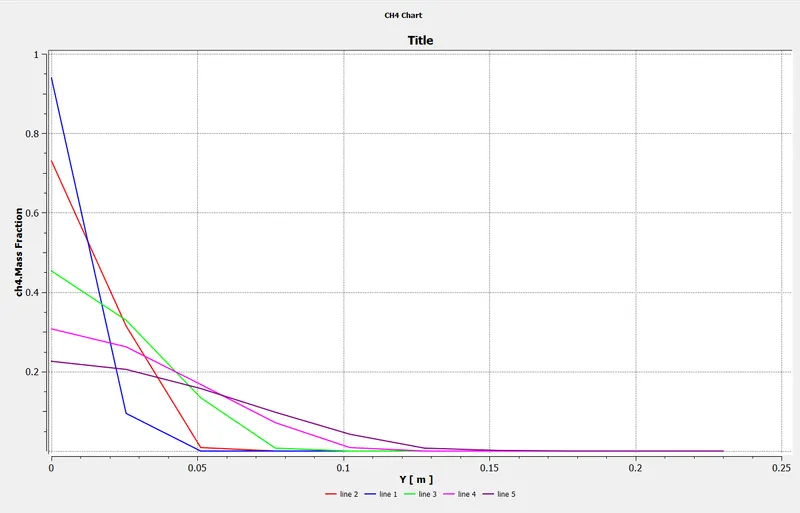
N2
Mass Fraction Contour
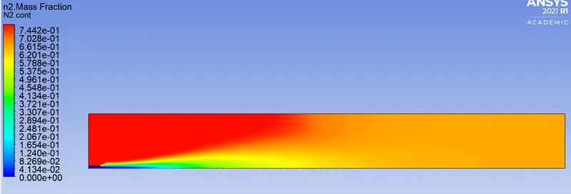
plot
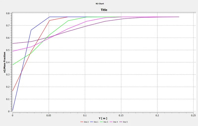
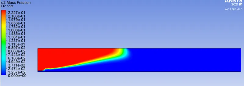
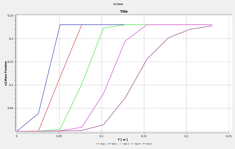
O2
Mass Fraction Contour
plot
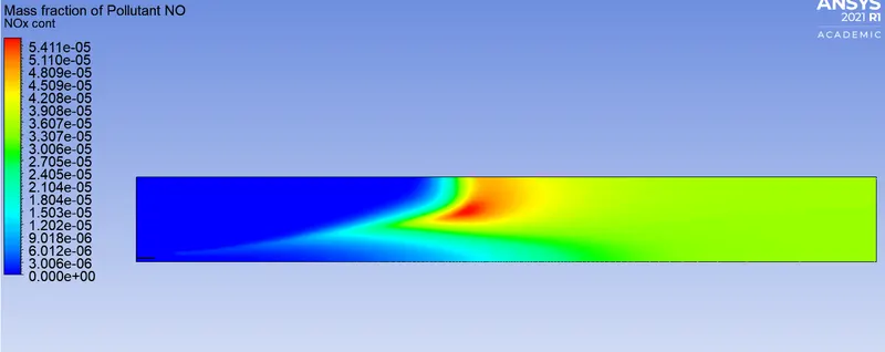
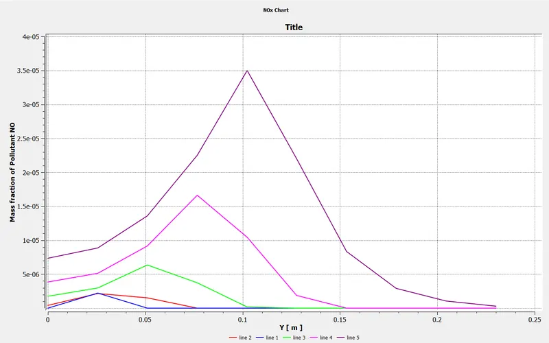
NOx emissions
Mass Fraction Contour
plot
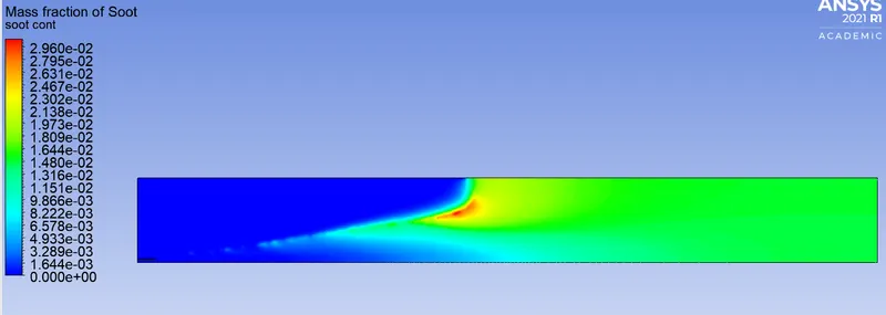
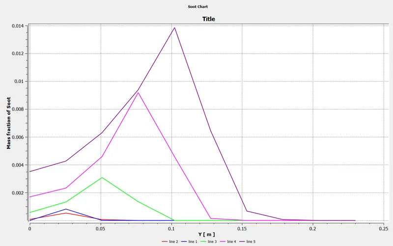
Soot formation
Mass Fraction Contour
plot
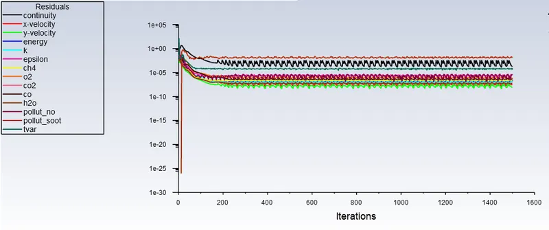
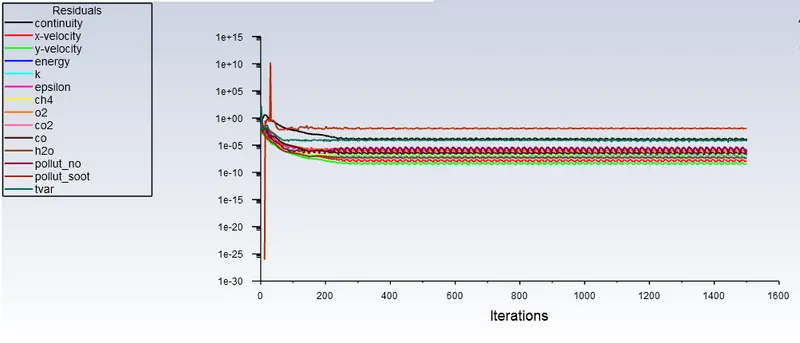
Case -3, 20% water in fuel inlet.
Residual
Temperature Contour
Mass Fraction
CO2
Mass Fraction Contour
plot
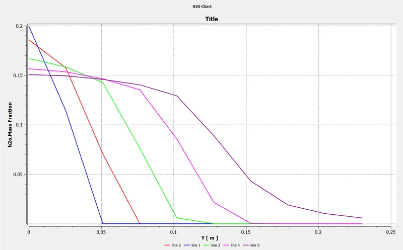
H2O
Mass Fraction Contour
plot
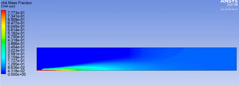
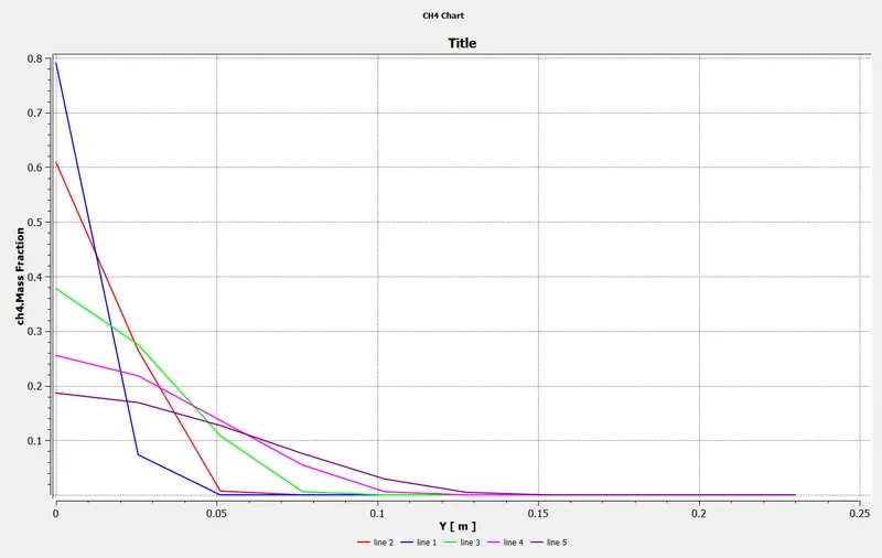
CH4
Mass Fraction Contour
plot
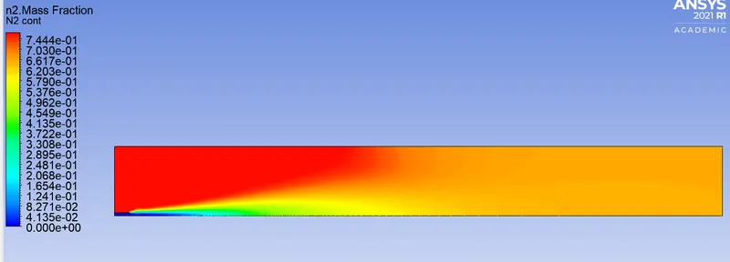
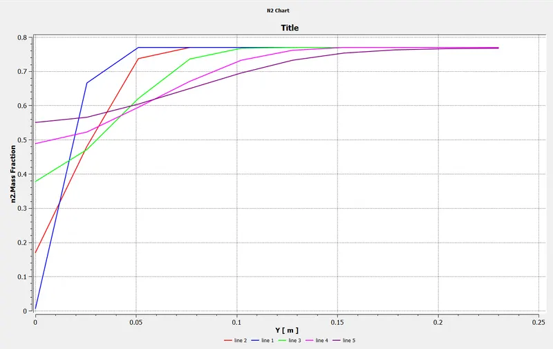
N2
Mass Fraction Contour
plot
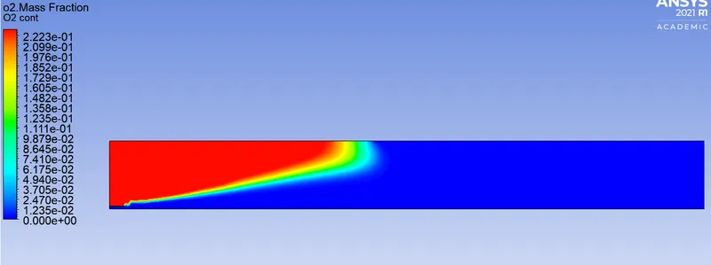
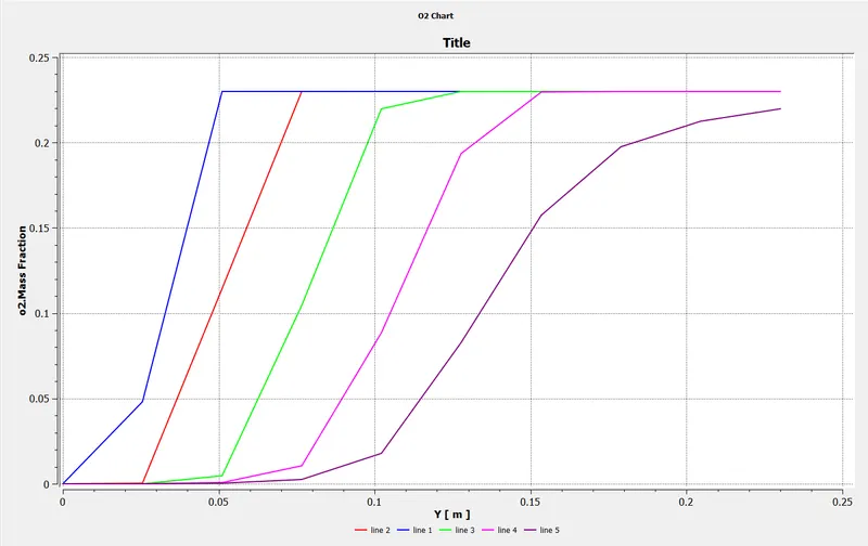
O2
Mass Fraction Contour
plot
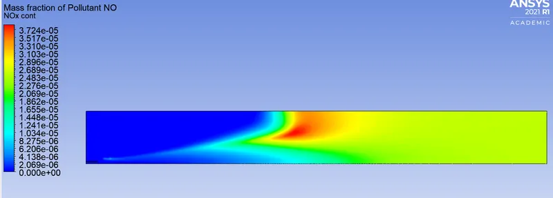
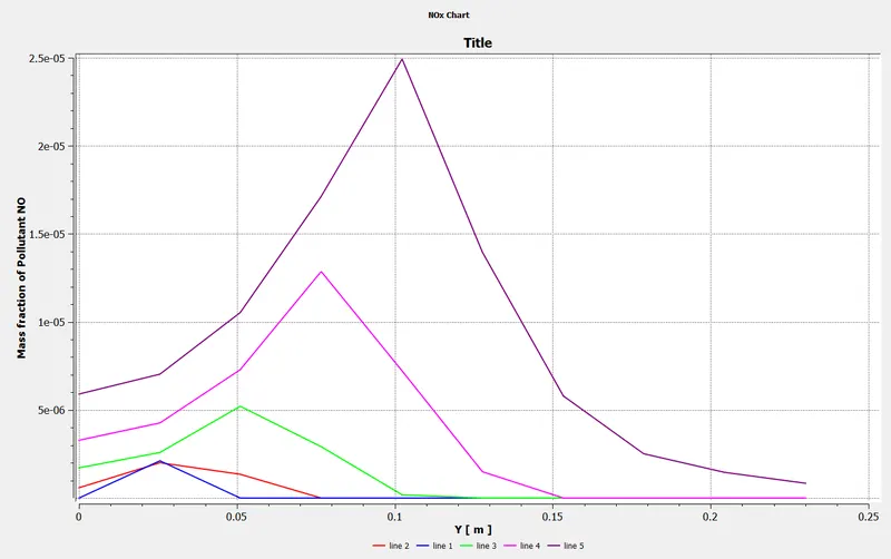
NOx emissions
Mass Fraction Contour
plot
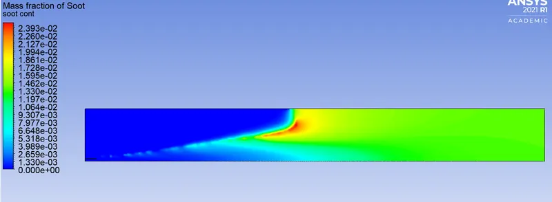
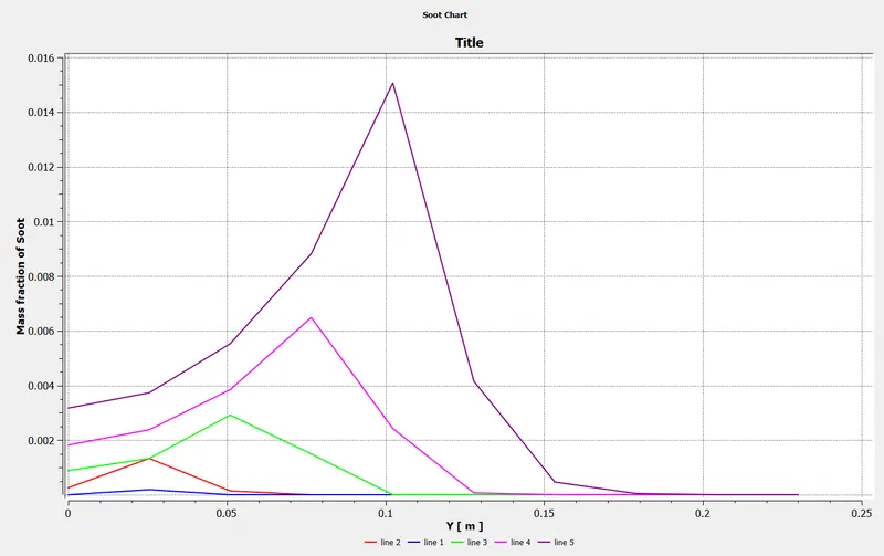
Soot formation
Mass Fraction Contour
plot
Case -4, 30% water in fuel inlet.
Residual
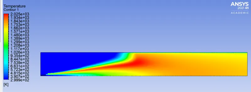
Temperature Contour
Mass Fraction
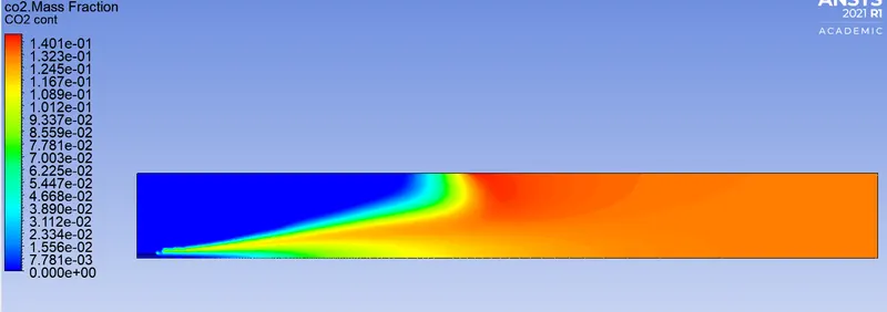
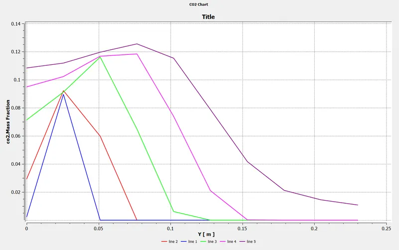
CO2
Mass Fraction Contour
plot
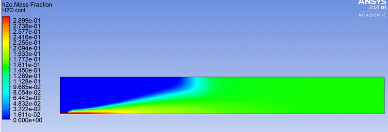
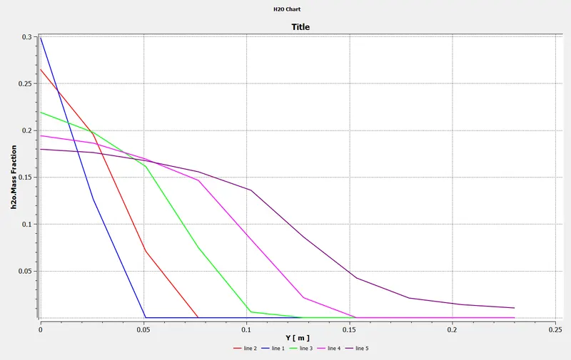
H2O
Mass Fraction Contour
plot
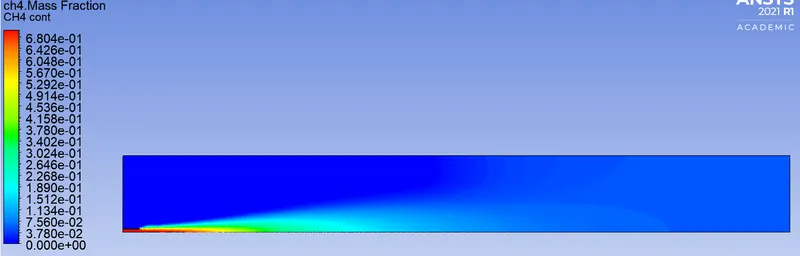
CH4
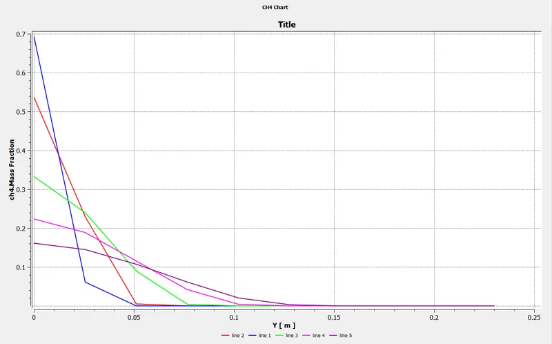
Mass Fraction Contour
plot
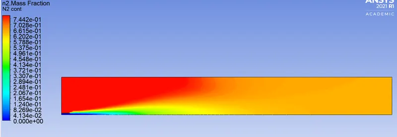
N2
Mass Fraction Contour
plot
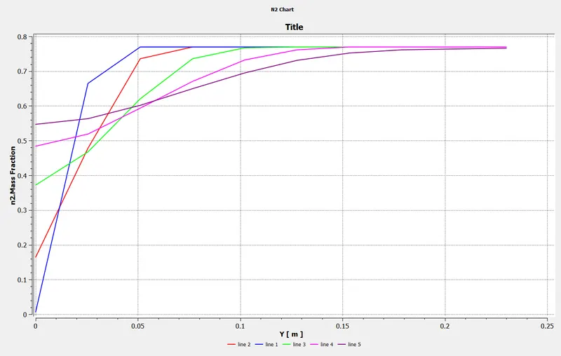
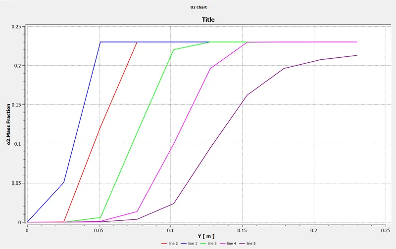
O2
Mass Fraction Contour
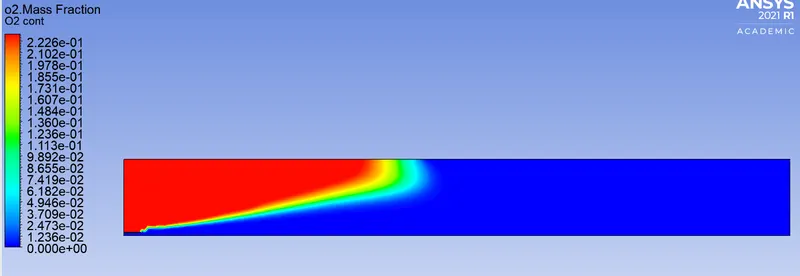
plot
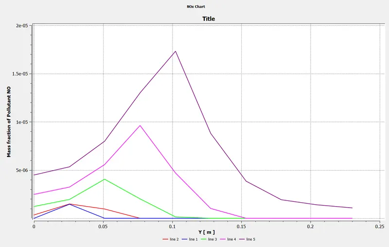
NOx emissions
Mass Fraction Contour
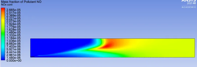
plot
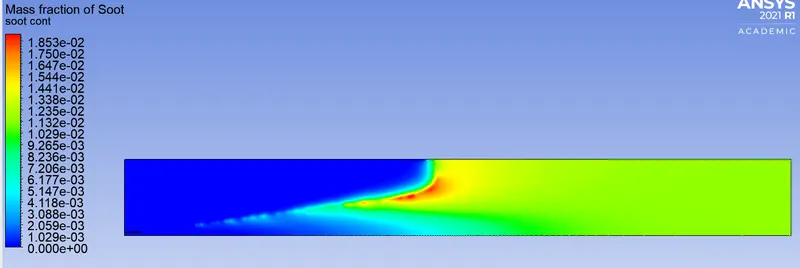
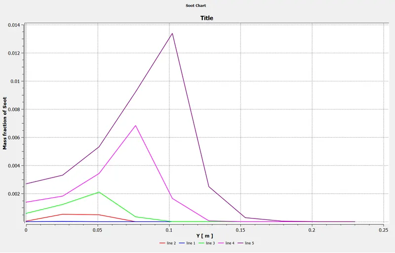
Soot formation
Mass Fraction Contour
plot
Inference:
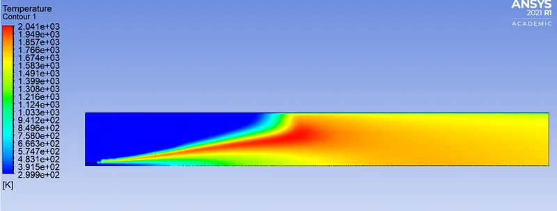
- The temperature drops as we add water to the fuel from 5 to 30%.
- The mass fraction of NO and soot decreases as we add water to the fuel by 5 to 30%.
- An improperly defined combustion settings type can lead to wrong results.
Conclusion:
- The steady-state simulation was performed successfully for methane-air and methane-air2step mixture.
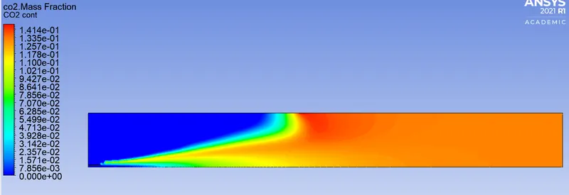
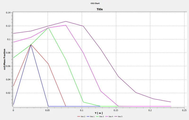
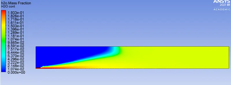
- The simulation performed by using methane-air mixture gave us insight about the temperature at the outlet, mass fraction of NOx and soot,CH4, N2, O2, H2O ,CO2 and six line-probes were drawn on plane-1 to observe their variation.
- As the mass fraction of water increases the temperature at the outlet decreases which further reduces any thermal damage from the hotspot region as such it could have damaged the region of the combustor.
- The increase in mass fraction of water brought down the levels of NOx and soot emission at the outlet which makes the combustion process environmentally friendly. The thermal NOx increases with an increase in temperature and with the greater concentration of O2 species. The addition of water lowers the temperature, thus decreasing the concentration of thermal NOx, that's why there is no change in the mass fraction of O2 for the six-line probes with an increase in mass fraction of water.
- The addition of water suppresses the NOx and the soot formation because it makes the fuel less rich.