Week 12- Major Project (CFD Analysis on Combustion in a SCRAMJET engine)
Aim:
To calculate the most efficient slot-fuel injector and cavity-flame holder for a scramjet in ANSYS Fluent.
Theory:
TURBOJET Engine:
The turbojet is an airbreathing jet engine typically used in aircraft. It consists of a gas turbine and a propelling nozzle. The gas turbine has an air inlet which includes inlet guide vanes, a compressor, a combustion chamber, and a turbine (that drives the compressor). The compressed air from the compressor is heated by burning fuel in the combustion chamber and then allowed to expand through the turbine. The turbine exhaust is then expanded in the propelling nozzle where it is accelerated to high speed to provide thrust.
Design:
- Air intake
- Compressor
- Combustion chamber
- Turbine
- Nozzle
- Thrust augmentation
- Afterburner
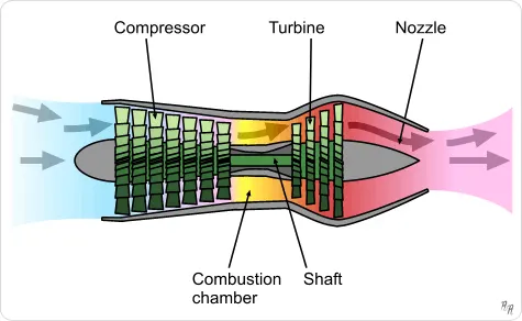
Figure: Turbojet engine
Ramjet Engine:
- A ramjet is a form of air-breathing jet engine that uses the forward motion of the engine to produce thrust. Since it produces no thrust when stationary (no ram air) ramjet-powered vehicles require an assisted take-off like a rocket assist to accelerate it to a speed where it begins to produce thrust. Ramjets work most efficiently at supersonic speed around Mach 3 (2,300 mph; 3,700 km/h) and can operate up to speeds of Mach 6 (4,600 mph; 7,400 km/h).
- Ramjets can be particularly useful in applications requiring a small and simple mechanism for high-speed use, such as missiles.
- As speed increases, the efficiency of a ramjet starts to drop as the air temperature in the inlet increases due to compression. As the inlet temperature gets closer to the exhaust temperature, less energy can be extracted in the form of thrust. To produce a usable amount of thrust at yet higher speeds, the ramjet must be modified so that the incoming air is not compressed (and therefore heated) nearly as much. This means that the air flowing through the combustion chamber is still moving very fast (relative to the engine), in fact, it will be supersonic—hence the name supersonic-combustion ramjet, or scramjet.
Design:
- The first part of a ramjet is its diffuser (compressor) in which the forward motion of the ramjet is used to raise the pressure of its working fluid (air) as required for the combustion of fuel. It is then passed through a nozzle to accelerate it to supersonic speeds. This acceleration gives the ramjet a forward thrust.
- A ramjet is much less complex than a turbojet in so far as it comprises an air intake, a combustor, and a nozzle but no turbomachinery.
Construction:
- Diffuser
- Combustor
- Nozzle
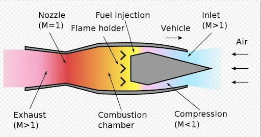
Figure: Ramjet
SCRAMJET (Supersonic Combustion RAMJET):
- A scramjet (supersonic combustion ramjet) is a variant of a ramjet airbreathing jet engine in which combustion takes place in supersonic airflow. As in ramjets, a scramjet relies on high vehicle speed to compress the incoming air forcefully before combustion (hence ramjet), but whereas a ramjet decelerates the air to subsonic velocities before combustion using shock cones, a scramjet has no shock cone and slows the airflow using shockwaves produced by its ignition source in place of a shock cone. This allows the scramjet to operate efficiently at extremely high speeds.
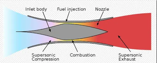
Figure: SCRAMJET
Design principle
- The scramjet is composed of three basic components: a converging inlet, where incoming air is compressed; a combustor, where gaseous fuel is burned with atmospheric oxygen to produce heat; and a diverging nozzle, where the heated air is accelerated to produce thrust.
- Unlike a typical jet engine, such as a turbojet engine, a scramjet does not use rotating, fan-like components to compress the air; rather, the achievable speed of the aircraft moving through the atmosphere causes the air to compress within the inlet.
- As such, no moving parts are needed in a scramjet. In comparison, typical turbojet engines require multiple stages of rotating compressor rotor, and multiple rotating turbine stages, all of which add weight, complexity, and a greater number of failure points to the engine.
- Due to the nature of their design, scramjet operation is limited to near hypersonic velocities. As they lack mechanical compressors, scramjets require the high kinetic energy of a hypersonic flow to compress the incoming air to operational conditions. Thus, a scramjet-powered vehicle must be accelerated to the required velocity (usually about Mach 4) by some other means of propulsion, such as turbojet or rocket engines.
- While scramjets are conceptually simple, the actual implementation is limited by extreme technical challenges. Hypersonic flight within the atmosphere generates immense drag, and temperatures found on the aircraft and within the engine can be much greater than that of the surrounding air.
Advantages of Scramjet:
- Does not have to carry oxygen
- No rotating parts make it easier to manufacture than a turbojet
- Has a higher specific impulse (change in momentum per unit of propellant) than a rocket engine
Disadvantage:
- Difficult/expensive testing and development
- Very high initial propulsion requirements
- Testing difficulties: Unlike jet or rocket propulsion systems facilities which can be tested on the ground, testing scramjet designs use extremely expensive hypersonic test chambers or expensive launch vehicles, both of which lead to high instrumentation costs.
Comparison:
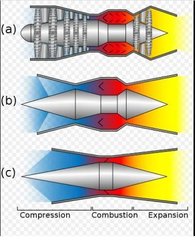
Figure: Compression, Combustion and Expansion region of (a) Turbojet (b) Ramjet and (c) SCRAMJET engines
CALCULATIONS:
Schematic Diagram:
A fuel opening is a little cylinder connected to the chamber of the primary motor, which fills in as the fuel inlet.
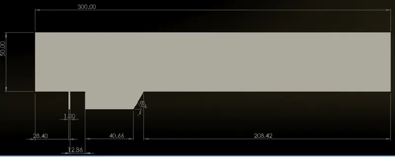
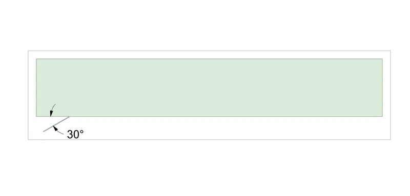
The angle here known as the fuel-injector point, will be varied through the simulations and the aftereffects of this variation will be seen.
A depression is an expansion from the tube of the primary motor, and fills in as a side-stop for burning with the goal that the fundamental wind stream isn't impacted. A single cavity is as seen underneath:
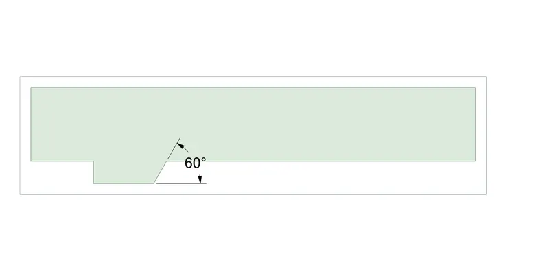
The noticeable angle is known as the point of cavity, which will be changed through the simulation, and its results will be seen.
The fuel utilized in the simulation is Hydrogen and the ignition response as follows:
2H2(g)+O2(g)→2H2O(g)+energy2H2(g)+O2(g)→2H2O(g)+energy
Combustion Efficiency (Ratio of burnt fuel to the total fuel for an engine):
here combustion efficiency(η) is quantified as,
η(combustion) = [m(burnt.H^2) ]/ [m(inlet.H^2)]
it is known that,
m(burnt.H^2) = [m(inlet.H^2)] - [m(unburnt.H^2)]
η(combustion) = { [m(inlet.H^2)] - [m(unburnt.H^2)] }/ [m(total.H^2)]
η(combustion) = 1− { [ m(unburnt.H^2) ] / [ m(inlet.H^2) ] }
hence,
m(unburnt.H^2) = mfrac(H^2,outlet) x mf(outlet)
Therefore,
η(combustion) = 1 - { [ mfrac(H^2,outlet) x mf(outlet) ] / mf(inlet) }
The simulation is separated into three cases, each case is additionally partitioned into various sub-cases. For each situation, the Combustion Efficiency will be determined.
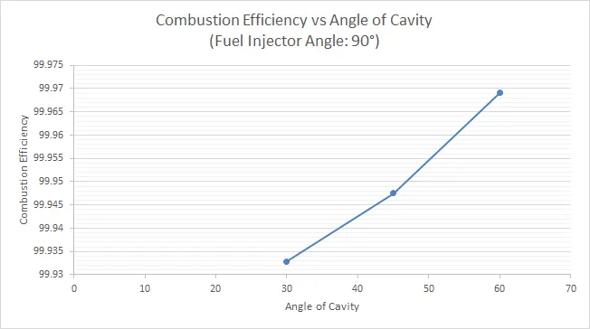
Case 1: The fuel-injector angle is fixed at 90 degrees, while the angle of cavity is set to 30, 45 and 60 degrees.
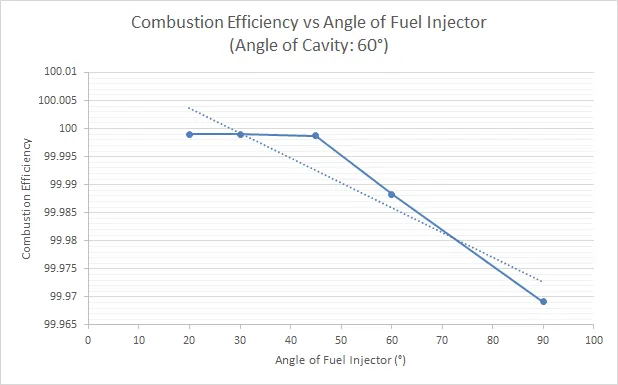
Case 2: The point of cavity is set to 60 degrees, while the fuel-injector angle is set to 20, 30, 45, 60 and 90 degrees.
Case 3: The fuel-injector is set inside the cavity, for various angles of cavity and fuel-injector angles.
Since finding the burning efficiency for 15 cases is infeasable and the objective for the task is to track down the most effective design for the motor. The plots for case 3 will be picked based on the outcomes from Case 1 and Case 2.
Procedure:
1) Geometry
- The geometry is created in SpaceClaim.
- The appropriate angles of cavity and fuel injector is given.
- This geometry is converted into a surface using the pull tool.
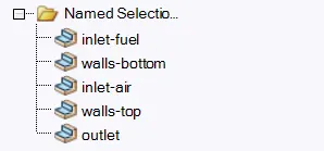
- Named selections are defined for all the boundaries.
geometry:
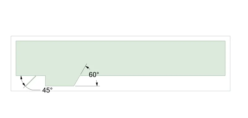
Named Selections:
2) Meshing:
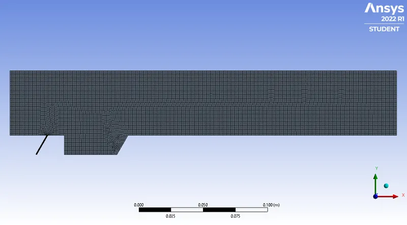
- The default quadrilateral mesh is used.
- Capture Proximity is turned on.
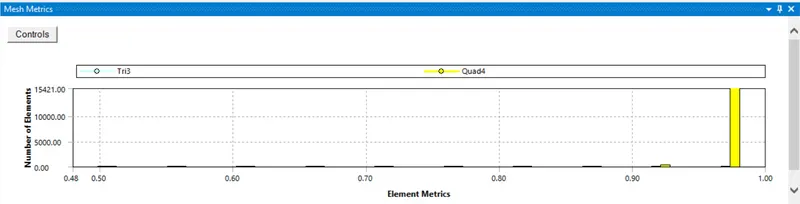
- Check the quality of mesh.
- most elements have quality greater than 0.9, hence the mesh can be used for further analysis.
mesh generated:
Quality of mesh:
3) Setup:
General Setting:
- Pressure Based
- 2D
- Steady state solver is used.
Materials:
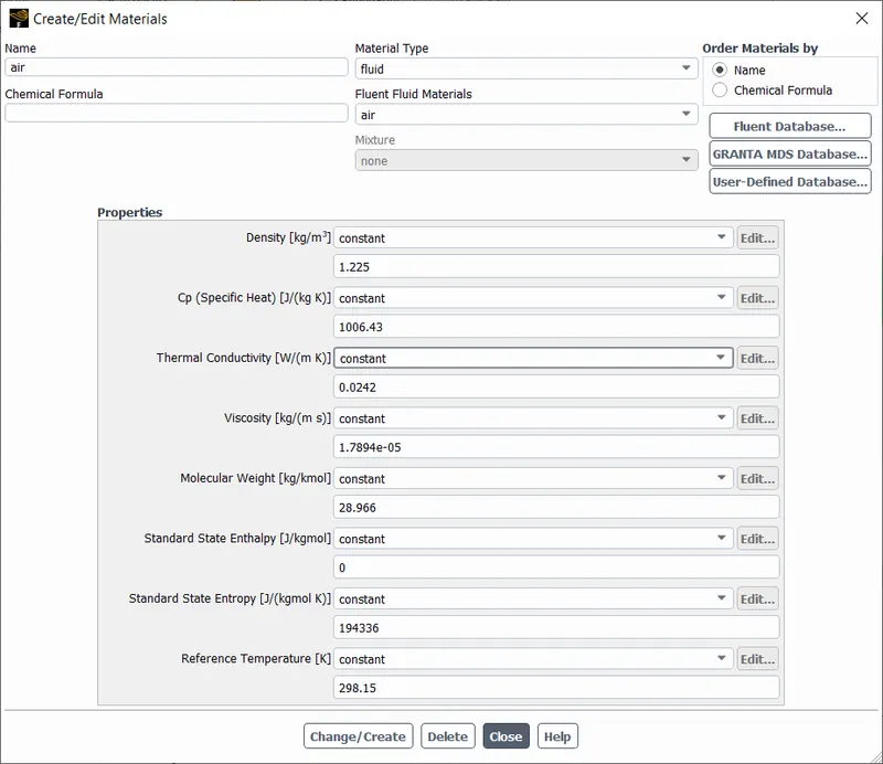
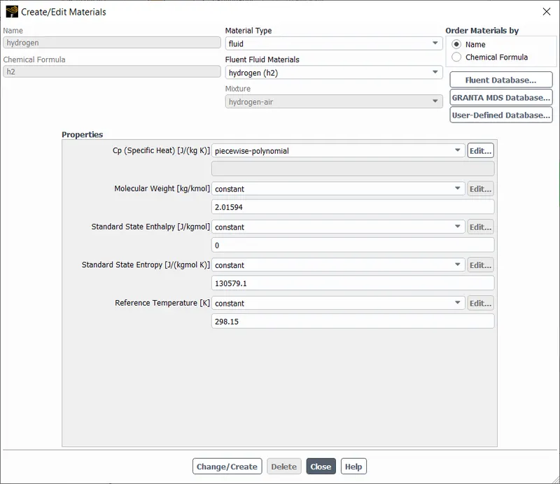
- The default properties of Air and Hydrogen gas (fluid) used for this simulation are shown below:
Air:
Hydrogen:
Turbulence Model:
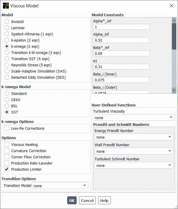
- k-omega SST model was used due to its flexibility in capturing boundary layers for any y+/velocity.
- Turbulence model was decided after literature review and was chosen from Reference [1].
Species Used:
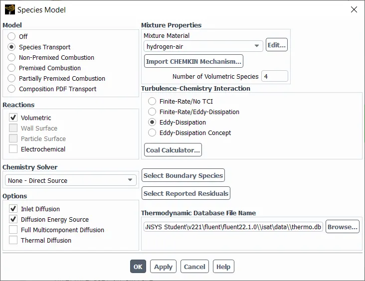
- to introduce Oxygen (O2) and Water(h20) species were added.
Boundary Conditions:
- inlet = air (velocity-inlet), velocity = 1040 m/s, Temperature = 600K, and O2 mole fraction = 0.21 (atmospheric air).
- inlet = fuel (velocity-inlet), velocity = 200 m/s, pressure = 500 bar (5x10^7 Pa), and H20 mole fraction = 1 (pure hydrogen).
- outlet = pressure-outlet, Pressure = 0Pa.
- walls bottom and walls top = stationary wall.
- Boundary conditions were decided after literature review and chosen from Reference [1].
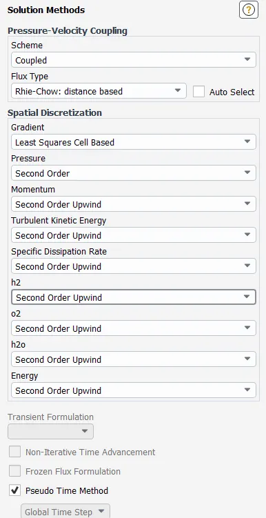
Solution Methods:
Report Monitors:
- Reports generated for each iteration are:
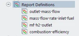
- User Defined Functions = One function was used to calculate the combustion efficiency using the following formula:
η(combustion) = 1 - { [ mfrac(H^2,outlet) x mf(outlet) ] / mf(inlet) }
Solution:
- The solution = hybrid intialised
- Number of iterations 200 or until the residuals dropped below 1e-4.
Results:
Qualitative Results
Temperature Contour
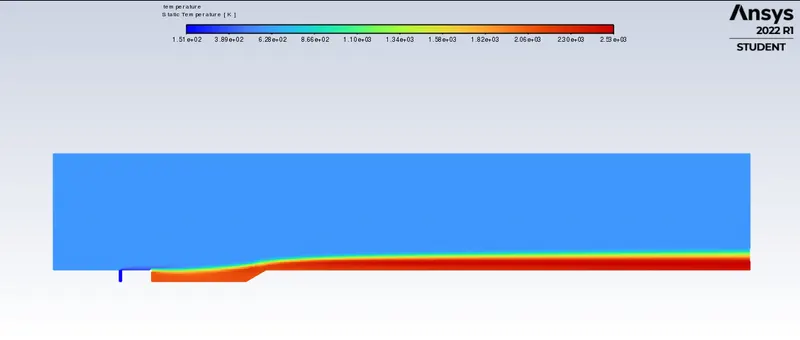
- The combustion produces heat.
- Most of the heat is generated in the cavity.
O2 Contour
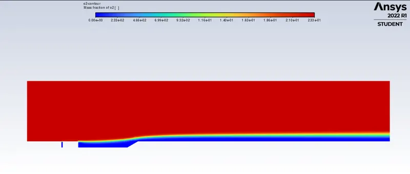
- The combustion has occoured in the depression.
- Oxygen is presnet in the cavity between fuel channel and depression, this additionally says that fuel doesn't promptly combust subsequent to entering the freestream.
H2 Contour
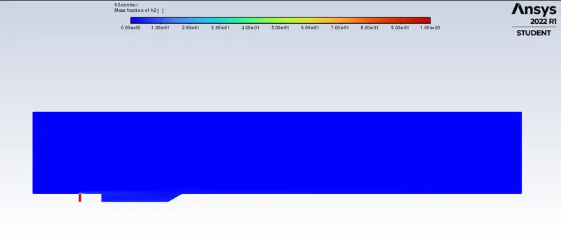
- All of the hydrogen fuel dissolves following entering the freestream flow
- This is on the grounds that the fuel proportion is incredibly low in this simulation (as just 1 fuel channel is being simulated). The fuel proportion is around 0.001.
H2O Contour
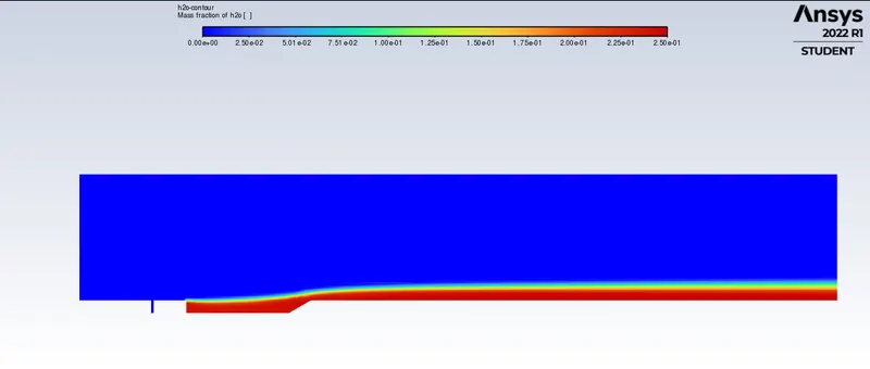
- Water is a result of the ignition response, which is simply seen to be created in the depression.
- This affirms that burning happens just in the pit and not elsewhere.
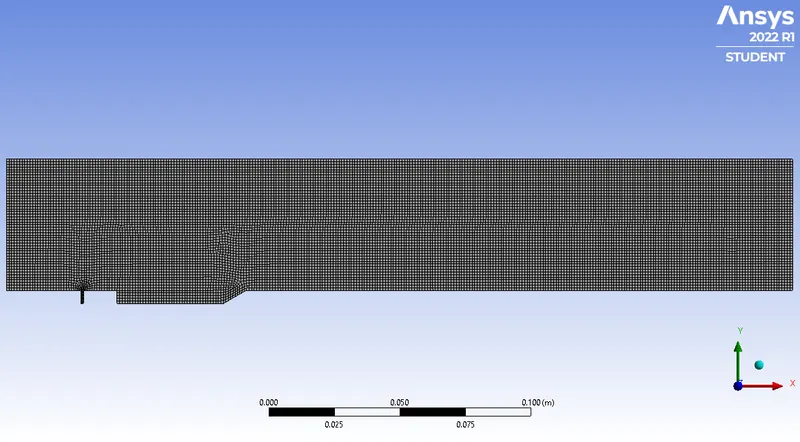
Case 1.1
- Angle of cavity: 30°
- Fuel Injector Angle: 90°
- Combustion Efficiency: 0.99932903
Mesh:
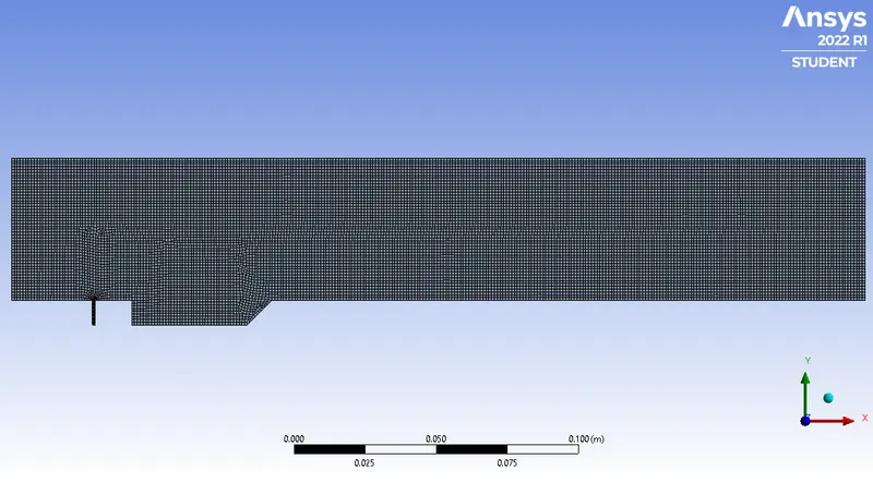
Case 1.2
- Angle of cavity: 45°
- Fuel Injector Angle: 90°
- Combustion Efficiency: 0.99947512
Mesh:
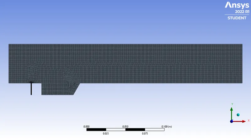
Case 1.3
- Angle of cavity: 60°
- Fuel Injector Angle: 90°
- Combustion Efficiency: 0.99969113
Mesh:
Case 2.1
- Angle of cavity: 60°
- Fuel Injector Angle: 20°
- Combustion Efficiency: 0.99999005
Mesh:
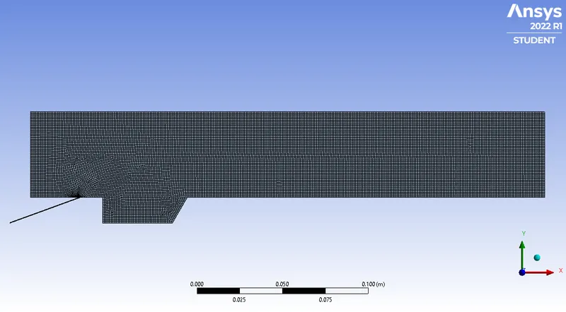
Case 2.2
- Angle of cavity: 60°
- Fuel Injector Angle: 30°
- Combustion Efficiency: 0.99999022
Mesh:
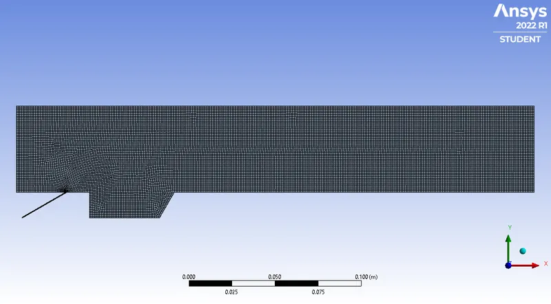
Case 2.3
- Angle of cavity: 60°
- Fuel Injector Angle: 45°
- Combustion Efficiency: 0.99998677
Mesh:
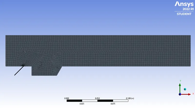
Case 2.4
- Angle of cavity: 60°
- Fuel Injector Angle: 60° (Ramp Injection)
- Combustion Efficiency: 0.99988288
Mesh:
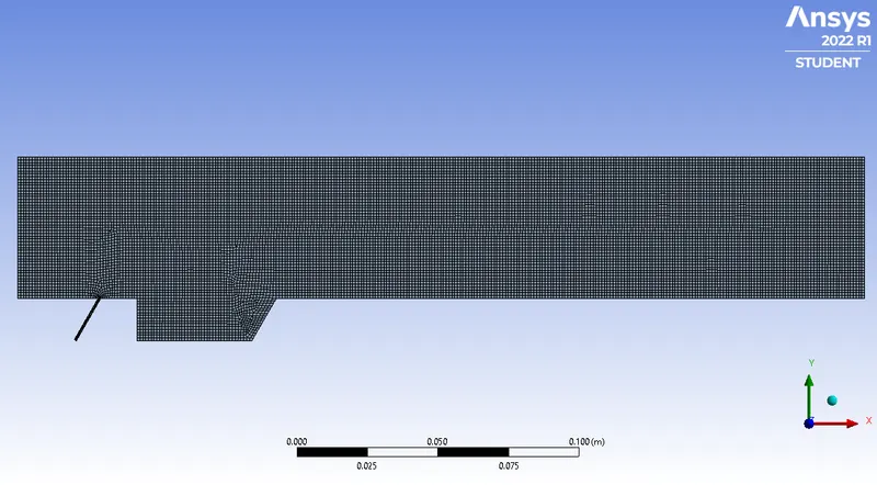
Case 2.5 (Same as case 1.3)
- Angle of cavity: 60°
- Fuel Injector Angle: 90° (Transverse Injection)
- Combustion Efficiency: 0.99969113
Mesh:
Case 3.1 (Fuel inside Cavity)
- Angle of cavity: 60°
- Fuel Injector Angle: 20°
- Combustion Efficiency: 1
- Mass Fraction of h2 at outlet: 1.1043768e-10
Mesh:
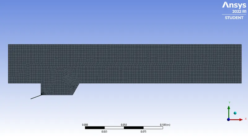
Case 3.2
-
Angle of cavity: 60°
-
Fuel Injector Angle: 30°
-
Combustion Efficiency: 1
- Mass Fraction of h2 at outlet: 3.4076226e-09
Mesh:
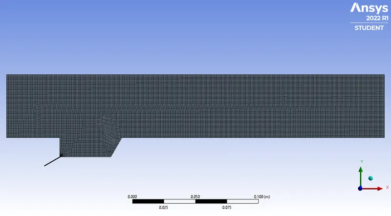
Case 3.3
- Angle of cavity: 45°
- Fuel Injector Angle: 20°
- Combustion Efficiency: 1
- Mass Fraction of h2 at outlet: 1.0374389e-10
Mesh:
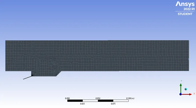
Case 3.4
- Angle of cavity: 45°
- Fuel Injector Angle: 30°
- Combustion Efficiency: 1
- Mass Fraction of h2 at outlet: 8.3984144e-09
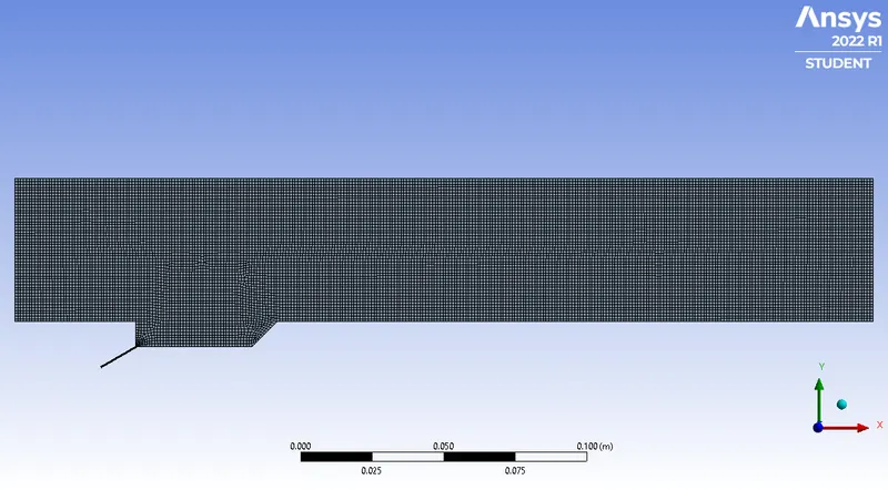
NOTE:
The combustion efficiency in case 3 is extremely high, due to all combustion of the fuel occuring in the cavity itself.
Summary of Results
Case 1 - Combustion Efficiency vs Angle of Cavity (Fuel Injector Angle: 90°)
| Angle of Cavity (°) | Combustion Efficiency (%) | Iterations |
| 30 | 99.932903 | 114 |
| 45 | 99.947512 | 166 |
| 60 | 99.969113 | 200 |
Case 2 - Combustion Efficiency vs Angle of Fuel Injector (Angle of Cavity: 60°)
| Angle of Fuel Injector (°) | Combustion Efficiency (%) | Iterations |
| 20 | 99.999005 | 105 |
| 30 | 99.999022 | 112 |
| 45 | 99.998677 | 200 |
| 60 | 99.988288 | 112 |
| 90 | 99.969113 | 200 |
Case 3 - Fuel Injector inside Cavity
| Angle of Fuel Injector (°) | Angle of Cavity (°) | Combustion Efficiency (%) | Mass Fraction of H2H2 at outlet | Iterations |
| 20 | 60 | 100 | 1.10E-10 | 169 |
| 30 | 60 | 100 | 3.41E-09 | 113 |
| 20 | 45 | 100 | 1.04E-10 | 166 |
| 30 | 45 | 100 | 8.40E-09 | 126 |
Conclusions:
- . The efficiency obtained is extremely high, but this is because of the presence of a single inlet for the entire engine.
-
Since all efficiencies were in the order of 99.99%, the convergence criteria was adjusted to 1e-4 to obtain more precise results.
-
In Case 2, the productivity increments as the depression angle increases, this can be because of expanded region during ignition when the angle of cavity is expanded. Expanded region brings about more complete burning.
-
In Case 2, the productivity diminishes as angle of fuel injector is expanded. This can be made sense of that as the angle diminishes, there is less obstacle of stream looked by the fuel, subsequently burning happens all the more rapidly and combusting particles are dispersed rapidly.
-
For Case 3, because of very high efficiences when the fuel channel is put in the cavity, the efficiencies might never again measure up. Rather, the power source mass part of H2 gas was analyzed.
- A 20° angle of fuel injector inside the cavity with angle of 60° can be concluded as the most efficient configuration in all the simulations conducted above. The fuel injector angle gives minimal resistance from stream/burning of fuel and cavity angle gives the most space to finish ignition.
References:
1. Choi, Jeong-Yeol & Ma, Fuhua & Yang, Vigor. (2005). Dynamic Combustion Characteristics in Scramjet Combustors with Transverse Fuel Injection. 41st AIAA/ASME/SAE/ASEE Joint Propulsion Conference and Exhibit. 10.2514/6.2005-4428.
- Erkumarsusheel549Hi
- Erkumarsusheel549Need your help desperately
- Erkumarsusheel549For this simulation
- Erkumarsusheel549It's very important for my work, please i would be grateful for your help
- Erkumarsusheel549Kindly get in touch with me on [email protected]. Thank you