Week 2 - Converging diverging nozzle
Converging diverging nozzle
Aim:
- To simulate the flow inside a converging diverging nozzle.
- To plot the pressure, temperature and density variation inside the nozzle
- To plot the variation of Mach number inside the nozzle , and find out at what distance the flow becomes supersonic.
Theory:
A convergent-divergent nozzle is a tube that is pinched in the middle, making a carefully balanced, asymmetric hourglass shape. It is used to accelerate a hot, pressurized gas passing through it to a higher supersonic speed in the axial (thrust) direction, by converting the heat energy of the flow into kinetic energy. Because of this, the nozzle is widely used in some types of steam turbines and rocket engine nozzles. It also sees use in supersonic jet engines.
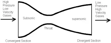
Similar flow properties have been applied to jet streams within astrophysics.
A convergent-divergent nozzle will only choke at the throat if the pressure and mass flow through the nozzle is sufficient to reach sonic speeds, otherwise no supersonic flow is achieved, and it will act as a Venturi tube; this requires the entry pressure to the nozzle to be significantly above ambient at all times (equivalently, the stagnation pressure of the jet must be above ambient).
In addition, the pressure of the gas at the exit of the expansion portion of the exhaust of a nozzle must not be too low. Because pressure cannot travel upstream through the supersonic flow, the exit pressure can be significantly below the ambient pressure into which it exhausts, but if it is too far below ambient, then the flow will cease to be supersonic, or the flow will separate within the expansion portion of the nozzle, forming an unstable jet that may "flop" around within the nozzle, producing a lateral thrust and possibly damaging it.
In practice, ambient pressure must be no higher than roughly 2–3 times the pressure in the supersonic gas at the exit for supersonic flow to leave the nozzle.
Working:
Its operation relies on the different properties of gases flowing at subsonic, sonic, and supersonic speeds. The speed of a subsonic flow of gas will increase if the pipe carrying it narrows because the mass flow rate is constant. The gas flow through a de Laval nozzle is isentropic (gas entropy is nearly constant). In a subsonic flow sound will propagate through the gas. At the "throat", where the cross-sectional area is at its minimum, the gas velocity locally becomes sonic (Mach number = 1.0), a condition called choked flow. As the nozzle cross-sectional area increases, the gas begins to expand and the gas flow increases to supersonic velocities where a sound wave will not propagate backward through the gas as viewed in the frame of reference of the nozzle (Mach number > 1.0).
As the gas exits the throat the increase in area allows for it to undergo a Joule-Thompson expansion wherein the gas expands at supersonic speeds from high to low pressure pushing the velocity of the mass flow beyond sonic speed.
When comparing the general geometric shape of the nozzle between the rocket and the jet engine, it only looks different at first glance, when in fact is about the same essential facts are noticeable on the same geometric cross-sections - that the combustion chamber in the jet engine must have the same "throat" (narrowing) in the direction of the outlet of the gas jet, so that the turbine wheel of the first stage of the jet turbine is always positioned immediately behind that narrowing, while any on the further stages of the turbine are located at the larger outlet cross section of the nozzle, where the flow accelerates.
Assumptions:
- The gas flow is ideal
- The gas flow is isentropic
Procedure:
The methodology of the simulation is as follows:
- Geometry creation in Ansys space claim
- Mesh generation
- Fluent set up
- Post processing in CFD post
1. Geometry :
By opening Ansys space claim, The converging diverging nozzle is created , with the following dimensions in meters.
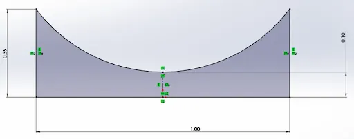
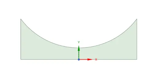
Since this is axisymmetric, the top half of the nozzle is prepared only, to save computational time.
2. Mesh generation:
- The geometry is saved and transferred to ansys mesher for the mesh generation.
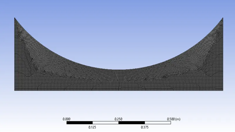
- Since this is a simple geometry, a general mesh will serve the purpose. Mesh is generated with following settings:
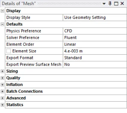
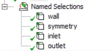
- And sections were named as follows:
3. Fluent set up:
- Operating conditions:
In this section , the reference pressure is set to zero. This is because only absolute pressure is considered in the simulation.
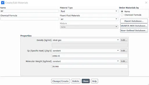
- Material selection:
Ansys fluent offers a wide variety of materials for the users to choose from. In this case, ideal gas is used.
- Physics set up:
energy is turned on, since temperature values are fluctuating in the flow.
Inviscid flow is selected, since ideal gas is dealt with.
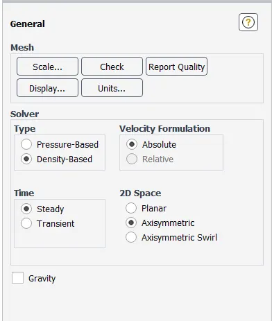
- General settings:
Density based solver is used.
with absolute velocity formulation.
steady state analysis for axisymmetric geometry.
gravitation is not turned on, since the flow is horizontal.
- Boundary conditions:
Inlet:
Boundary type : Pressure inlet.
Gauge total pressure is specified for the inlet.
Initial Gauge pressure = 100000 pas.
Temperature at the inlet is 300K
Outlet:
Boundary type: Pressure outlet
Gauge pressure is specified for the outlet.
Back flow total temperature =300K
Nozzle wall:
Wall boundary conditions are specified.
Axisymmetric edge:
Symmetry boundary condition is specified.
- Initialization:
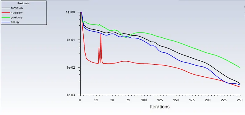
The convergence criterion is set to 1e-03
Hybrid initialization is done
The simulation is run for 500 iterations
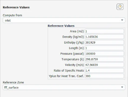
- Reference conditions:
For the reference condition, the flow parameters are calculated from inlet.
4. Post processing in CFD post
- Contours and plots:
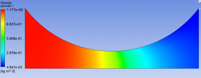
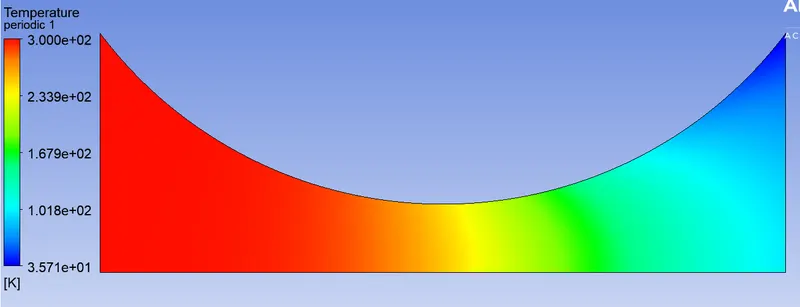
- Contours of temperature, pressure, velocity and density are created along the nozzle.
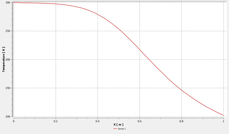
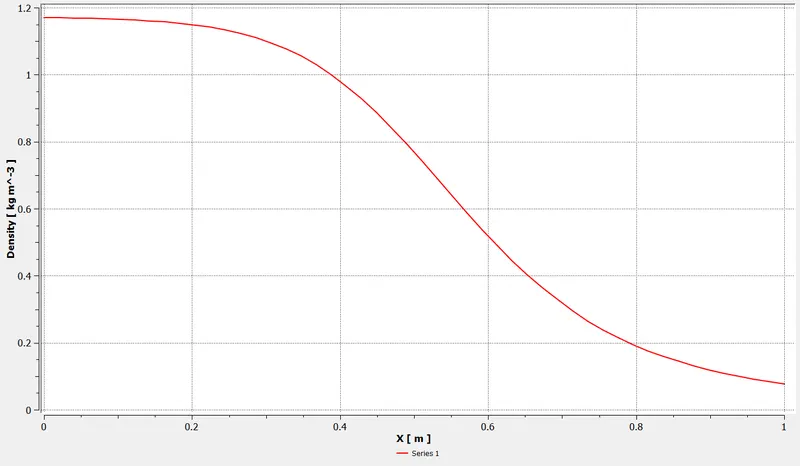
- In the data files, xy plots are added, along the x axis, a line probe is inserted axi symmetric edge. Along the Y axis, velocity, density, pressure and Temperature is plotted along the. With these plots, the variation of these parameters along the nozzle can be monitored. This is particularly important for the validation of the results part.
Solution:
The simulation is run for 250 iterations, The plots are shown below:
Residuals:
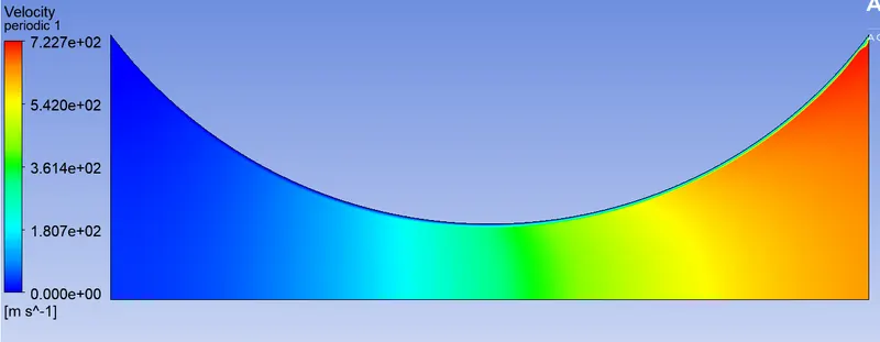
Velocity contour:
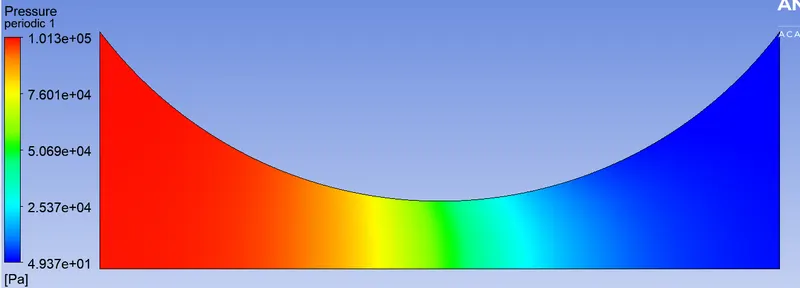
Pressure contour:
Density contour:
Temperature contour:
Plots:
1) Temperature plot along the line probe:
2) The density plot along the line probe:
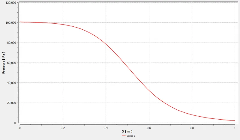
3) Pressure plot along the line probe:
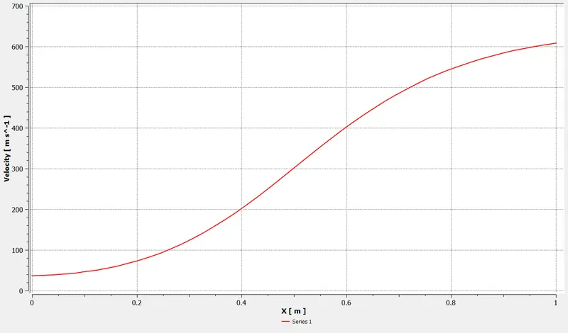
4) Mach number distribution along the line probe:
Observation
- At inlet the Mach number is less than 1, this means at the inlet, the flow is subsonic. The flow changes from subsonic to supersonic (above 343m/s) at a distance between 0.5 meters to 0.55 meters from the inlet .
- Supersonic flow is when the Mach number is 1.2 or more and less than 6. In the above plot, the mach number reaches 1, at a distance between 0.5 m and 0.55 m from the inlet.
- At the inlet, temperature is high, at the outlet temperature is low.
- Similarly, towards the outlet, the static pressure is less and so is density.
- From the contours it is seen that the velocity increases towards the outlet.