Week 9 - Parametric study on Gate valve.
Aim:
To perform a parametric study on the gate valve simulation by setting the valve lift from 10% to 80%.
Introduction:
Gate Valve
A gate valve, also known as a sluice valve, is a valve that opens by lifting a gate out of the path of the fluid. Gate valves require very little space along the pipe axis and hardly restrict the flow of fluid when the gate is fully opened. The gate faces can be parallel but are most commonly wedge-shaped.
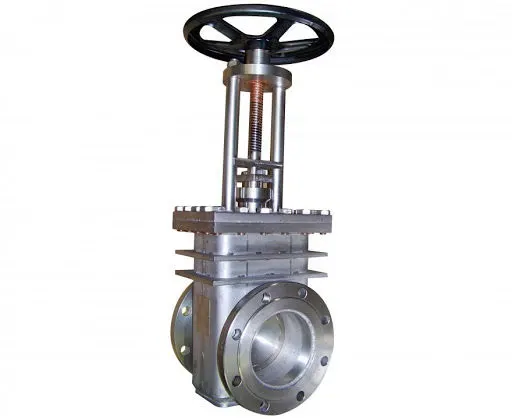
Gate valves are used to shut off the flow of liquids rather than for flow regulation. When fully open, the typical gate valve has no obstruction in the flow path, resulting in very low flow resistance. The size of the open flow path generally varies in a nonlinear manner as the gate is moved. This means that the flow rate does not change evenly with stem travel. Depending on the construction, a partially open gate can vibrate from the fluid flow. Gate valves without an extra sealing ring on the gate or the seat are used in applications where minor leaking of the valve is not an issue, such as heating circuits or sewer pipes. Gate valves are mostly used with larger pipe diameters (from 2" to the largest pipelines) since they are less complex to construct than other types of valves in large sizes. The given valve model, as an overview, consists of a hand wheel, spindle, the gate disc, bonnet and seat on either side of the main body. Hand wheel connected to the spindle allows for more often linear motion of the gate disc. Bonnet protects the contained internal moving parts of the assembled model and can be removed at different intervals to perform the necessary maintenance and/or replacement activities of the different components. Gate valve assemblies vary in configuration and are often classified based on the types of disk, types of body bonnet joint and types of stem movement.
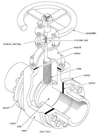
Advantage of gate valve assemblies include use of different media like slurries and viscous fluids, bi-directional flow, easier maintenance and disassembly, relatively inexpensive, available in large size, operational as shut-off valve and usually fire-safe for metal sheet based construction. Drawbacks are limitation on lower pressure valves, operational time is slow either during opening or closing, disk and seat erosion depending on the prevalent conditions, poor throttling features, repair of parts are difficult and is best avoided in sanitary based applications.
Parametric Study in Fluent
During CFD simulations involving multiple cases, it becomes difficult to set the case separately for each different case. Hence, Parameter option can be used in Fluent by running the case once and obtaining result of different cases by changing the Design parameter.
This can be utilised by clicking on the P button when using the move option.
Flow Coefficient and Flow Factor
The flow coefficient of a device is a relative measure of its efficiency at allowing fluid flow. It describes the relationship between the pressure drop across an orifice valve or other assembly and the corresponding flow rate.
Mathematically the flow coefficient Cv be expressed as :
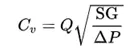
where:
Q is the rate of flow (expressed in US gallons per minute),
SG is the specific gravity of the fluid (for water = 1),
ΔP is the pressure drop across the valve (expressed in psi).
Flow Factor:
The metric equivalent flow factor (Kv; commonly used everywhere else in the world with the exception of the United States) is calculated using metric units:
Kv can be calculated from Cv
using the equation: Kv=0.865⋅Cv
Procedure:
Geometry Preparation
- import the step file for the gate valve
- Using the pull option, the surface is pulled by 800mm on each side, as shown below.
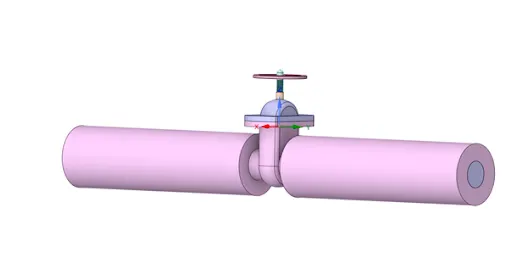
- extract a fluid volume by 'extract volume' option, by selecting inlet and outlet and edge above the body. Then suppress the surface body of the cyclone separator for physics.
- Using the move option, the gate disc was moved initially by 10mm upwards and then, a group parameter was created to conduct the Parameter study.
Meshing
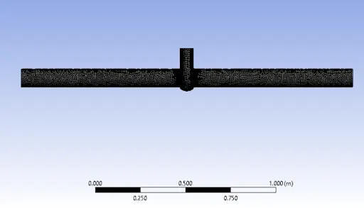
- Under mesh settings, select the element size as 0.009 meters. (The refinement is enough to get accurate results)
- Then provide named selections , on one end provide inlet and the opposite end provide outlet named selection.
Setup
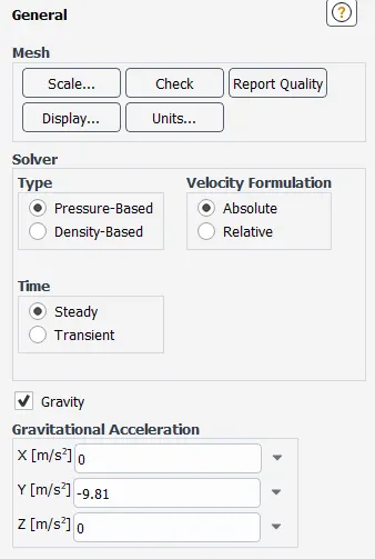
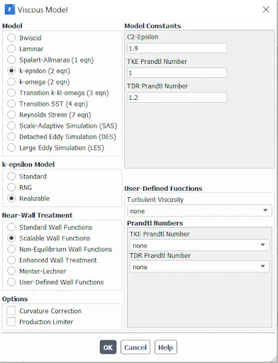
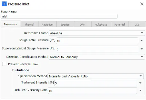
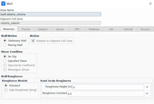
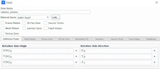
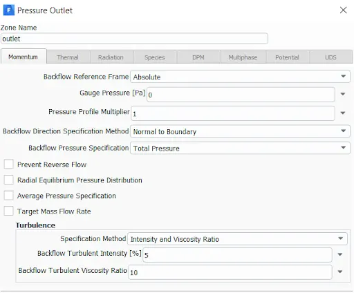
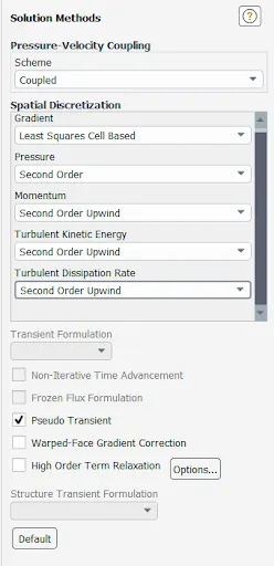
Follow the settings as shown in the images below:
- General settings
- Viscous model
- Boundary and Initial conditions
- solution methods
- solution initialization
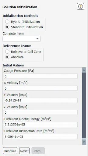
- Run the simulation for 600 iterations.
- export the particle history data and save it.
Observation:
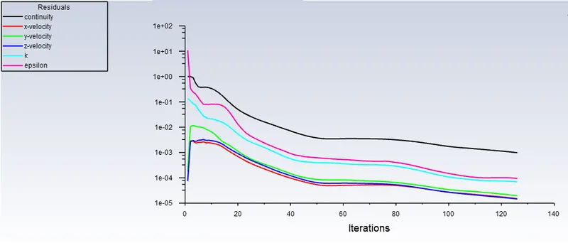
Case - 1 (10% lift)
Residuals:
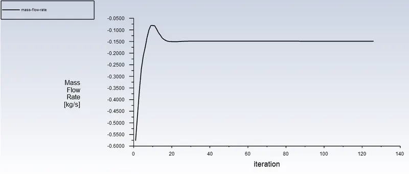
Mass flow rate:
Mass Flow Rate= -0.14846 kg/s
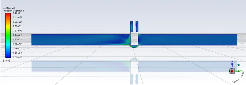
Velocity contour:
Flow Coefficient:
Cv=0.75
Flow Factor:
Kv=0.64
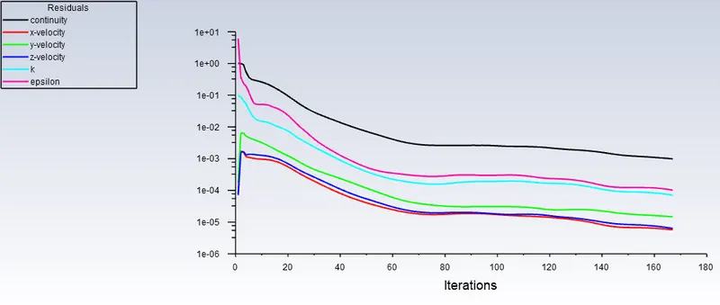
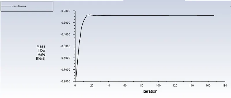
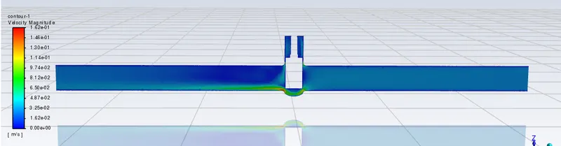
Case - 2 (20% lift)
Residuals:
Mass flow rate:
Mass Flow Rate= -0.23871 kg/s
Velocity contour:
Flow Coefficient:
Cv=1.12
Flow Factor:
Kv=1.03
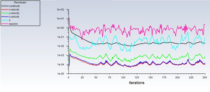
Case - 3 (30% lift)
Residuals:
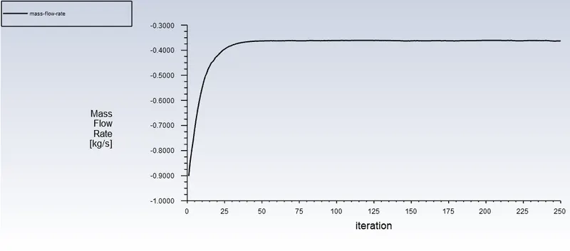
Mass flow rate:
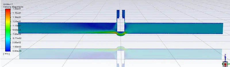
Mass Flow Rate= -0.36108 kg/s
Velocity contour:
Flow Coefficient:
Cv=1.82
Flow Factor:
Kv=1.57
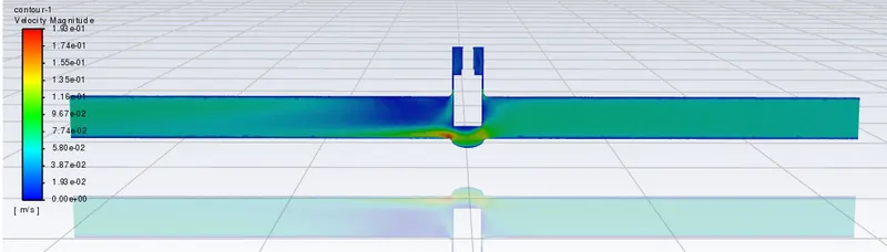
Case - 4 (40% lift)
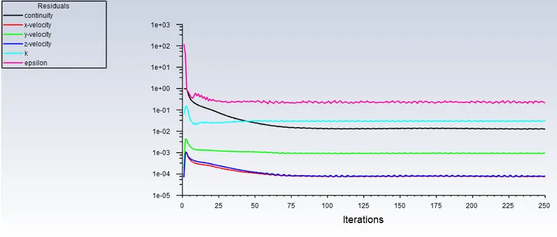
Residuals:
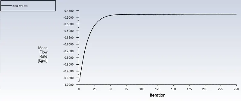
Mass flow rate:
Mass Flow Rate= -0.46781 kg/s
Velocity contour:
Flow Coefficient:
Cv=2.31
Flow Factor:
Kv=1.99
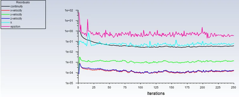
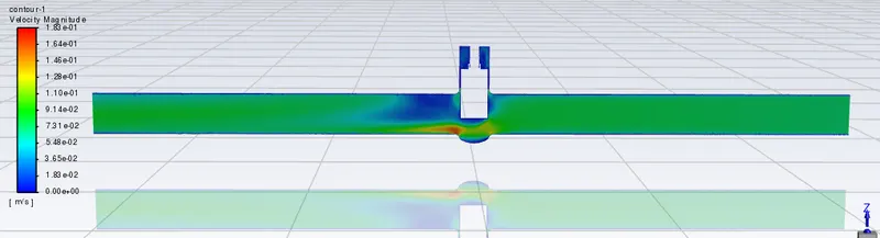
Case - 5 (50% lift)
Residuals:
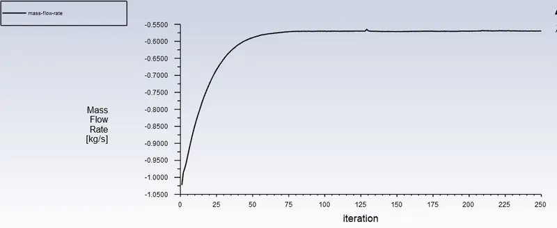
Mass flow rate:
Mass Flow Rate= -0.56009 kg/s
Velocity contour:
Flow Coefficient:
Cv=2.8
Flow Factor:
Kv=2.45
Case - 6 (60% lift)
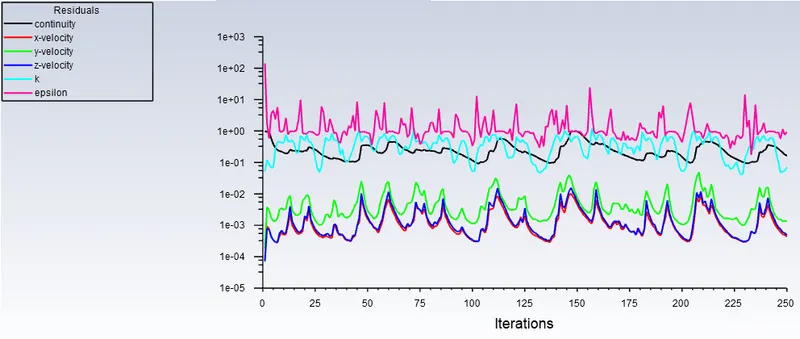
Residuals:
Mass flow rate:
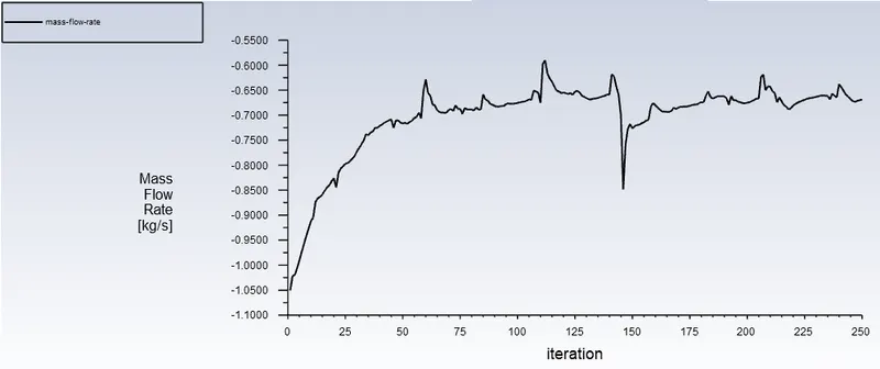
Mass Flow Rate= -0.63218 kg/s
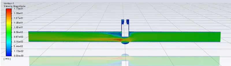
Velocity contour:
Flow Coefficient:
Cv=3.16
Flow Factor:
Kv=2.74
Case - 7 (70% lift)
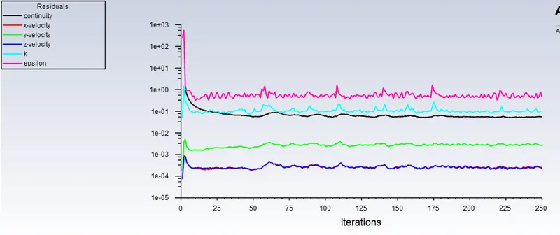
Residuals:
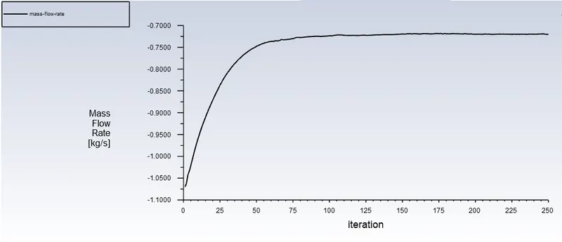
Mass flow rate:
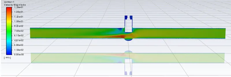
Mass Flow Rate= -0.71669 kg/s
Velocity contour:
Flow Coefficient:
Cv=3.57
Flow Factor:
Kv=3.08
Case - 8 (80% lift)
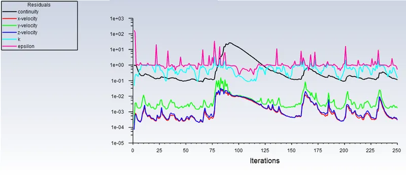
Residuals:
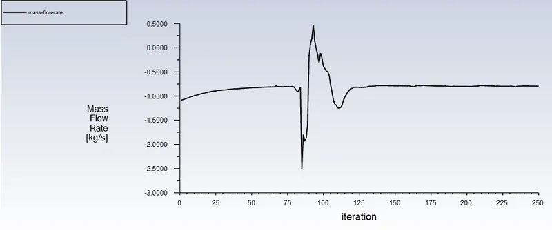
Mass flow rate:
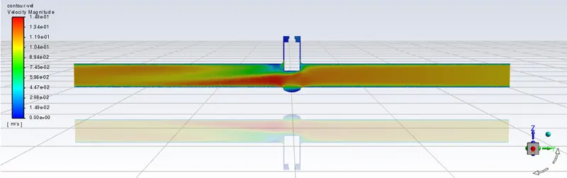
Mass Flow Rate= -0.84422 kg/s
Velocity contour:
Flow Coefficient:
Cv=4.23
Flow Factor:
Kv=3.66
Graphs:
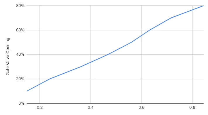
LIFT VS MASS FLOW RATE:
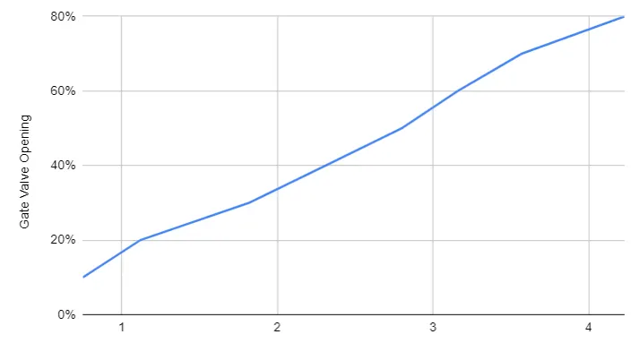
LIFT VS FLOW COEFFICIENT:
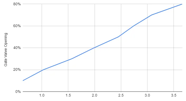
LIFT VS FLOW FACTOR:
Inference:
- Mass flow rate, flow coefficient and flow factor increases as the opening of gate valve increases.
- The mass flow rate, flow coefficient and flow factor increases linearly with respect to gate disc opening.
- The pressure is high at the inlet side and lower at the outlet side thus the flow takes place due to pressure difference.
Conclusion:
- From the observations we can conclude that the velocity of flow increases as the opening or lift of gate disc increases.