Simulating Cyclone separator with Discrete Phase Modelling
Aim:
To perform steady state analysis on a cyclone separator and calculate the separation efficiency and pressure drop.
Theory:
Cyclone Separator
CYCLONES are probably the most widely used dust collecting devices. They are relatively simple and inexpensive to fabricate, operate with moderate pressure losses, and if properly applied, give long trouble free service. Efficiency is generally good for dust where particles are larger than about 5 ~m in dia. Cyclones are frequently used as final collectors where large particles are to be caught. They can also be used as precleaners for a more efficient collector such as an electrostatic precipitator, scrubber or fabric filter.
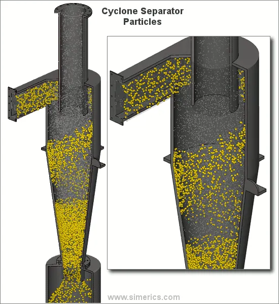
Cyclone separators work much like a centrifuge, but with a continuous feed of dirty air. In a cyclone separator, dirty flue gas is fed into a chamber. The inside of the chamber creates a spiral vortex, similar to a tornado. This spiral formation and the separation is shown in Figure . The lighter components of this gas have less inertia, so it is easier for them to be influenced by the vortex and travel up it. Contrarily, larger components of particulate matter have more inertia and are not as easily influenced by the vortex.
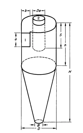
Since these larger particles have difficulty following the high-speed spiral motion of the gas and the vortex, the particles hit the inside walls of the container and drop down into a collection hopper. These chambers are shaped like an upside-down cone to promote the collection of these particles at the bottom of the container. The cleaned flue gas escapes out the top of the chamber.
Cyclones are particularly well suited for high temperature and pressure conditions because of their rugged design and flexible component materials. Cyclone collection efficiencies can reach 99% for particles bigger than 5 µm, and can be operated at very high dust loading. Cyclones are used for the removal of large particles for both air pollution control and process use.
Application in extreme conditions includes the removal of coal dust in a power plant and the use as a spray dryer or gasification reactor. Engineers are generally interested in two parameters in order to carry out an assessment of the design and performance of a cyclone. These parameters are the collection efficiency of particles and pressure drop through the cyclone. An accurate prediction of cyclone efficiency is very important because an inaccuracy in the efficiency prediction may result in an inefficient design of the cyclone separator. CFD has a great potential to predict the flow field characteristics and particle trajectories inside the cyclone as well as the pressure drop.
The complicated swirling turbulent flow in a cyclone places great demands on the numerical techniques and the turbulence models employed in the CFD codes when modelling the cyclone pressure drop.
Models to calculate efficiency
- Iozia and Leith Model
The Iozia and Leith logistic model is a modified version of the Barth Model, which is developed based on force balance. The model assumes that a particle carried by the vortex endures the influence of two forces: a centrifugal force, Z and a flow resistance, W. The collection efficiency ηi of particle diameter dpi can be calculated from
ηi= 11 + [(dpc/dpi)^β]
β is an expression for slope parameter derived based on the statistical analysis of experimental data of a cyclone with D=0.25 m given as
β=(0.62) − [0.87 x ln(dpc/100)] + [5.21 x ln(ab/D^2)] + 1.05 x [ln(ab/D^2)]^2
and dpc is the 50 % cut size.
- Li and Wang Model
The Li and Wang model includes particle bounce or reentrainment and turbulent diffusion at the cyclone wall. A two dimensional analytical expression of particle distribution in the cyclone is obtained. Li and Wang model was developed based on the following assumptions:
- The radial particle velocity and the radial concentration profile are not constant for uncollected particles within the cyclone.
- Boundary conditions with the consideration of turbulent diffusion coefficient and particle bounce reentrainment on the cyclone wall are:
C=C0, at θ=0
Dr (∂c/∂r) = (1−α)ωc, at r=D/2
The tangential velocity is related to the radius of the cyclone by = μR=constant.
The concentration distribution in a cyclone is given as:
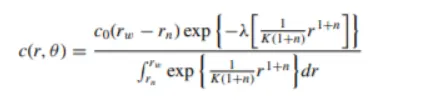
where
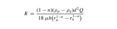
and
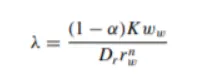
The resultant expression of the collection efficiency for particle of any size is given as
ηi = 1 − exp{ −λθ1 }
Where
θ1=2π(S+L) / α
- Koch and Licht Model
Koch and Licht collection theory recognized the inherently turbulent nature of cyclones and the distribution of gas residence times within the cyclone. Koch and Licht described particle motion in the entry and collection regions with the additional following assumptions:
- The tangential velocity of a particle is equal to the tangential velocity of the gas flow, i.e. there is no slip in the tangential direction between the particle and the gas.
The tangential velocity is related to the radius of the cyclone by= uR^n=constant.
A force balance and an equation on the particles collection yields the grade efficiency ηi
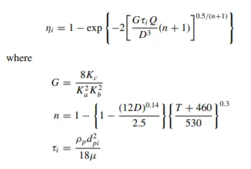
G is a factor related to the configuration of the cyclone, n is related to the vortex and 𝝉 is the relaxation term.
- Lapple Model
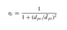
Lapple model was developed based on force balance without considering the flow resistance. Lapple assumed that a particle entering the cyclone is evenly distributed across the inlet opening. The particle that travels from inlet half width to the wall in the cyclone is collected with 50% efficiency. The semi empirical relationship developed by Lapple to calculate a 50% cut diameter, dpc, is
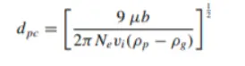
Where Ne is the number of revolutions
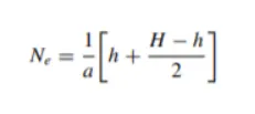
The efficiency of collection of any size of particles is given by
Procedure:
Geometry Preparation
- import the step file for the cyclone separator
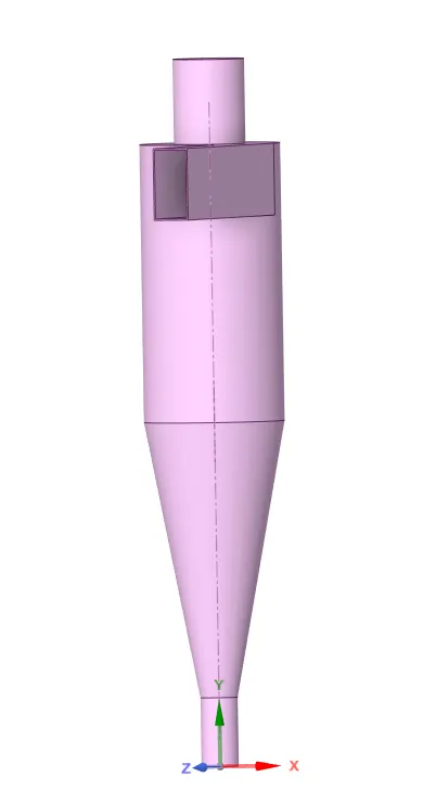
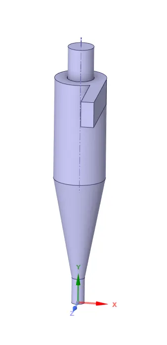
- extract a fluid volume by 'extract volume' option, by selecting inlet and outlet edges. And suppress the surface body of the cyclone separator for physics.
Meshing
- under mesh settings, select the element size as 0.006 meters. (this element size is restricted due to license issues, but the refinement is enough to get accurate results)
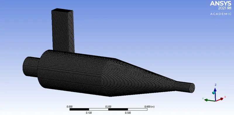
- after meshing name the faces, to assign inlet (named -inlet), outlet for filtered air (named- outlet 1), and outlet for collecting the particles (named- outlet 2).
Setup
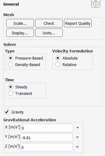
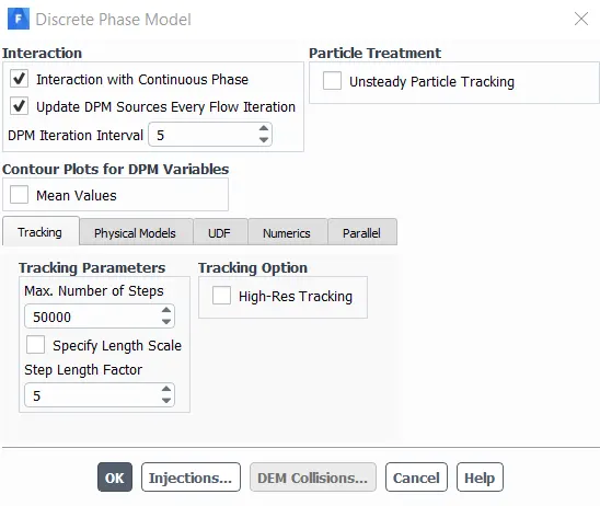
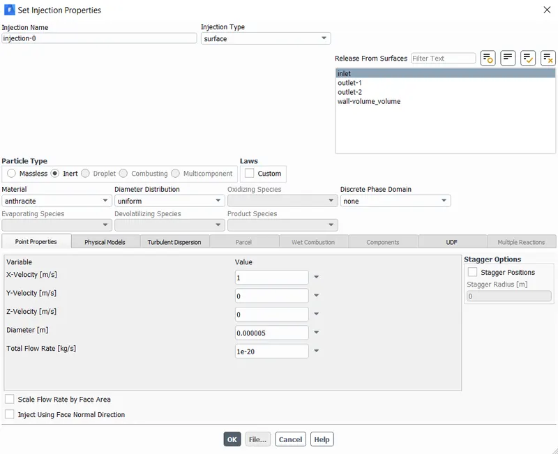
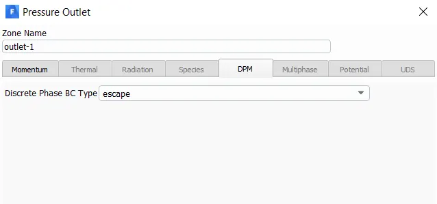
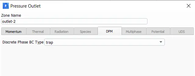
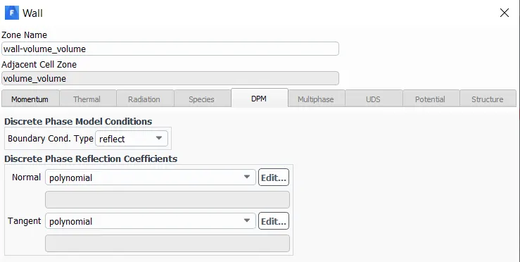
Follow the settings as shown in the images below:
- General settings
- Viscous model

- Discreet Phase Modelling and injection settings
- Boundary and Initial conditions
Initial Condition
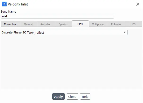
Boundary Conditions
- solution methods
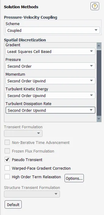
- solution initialization
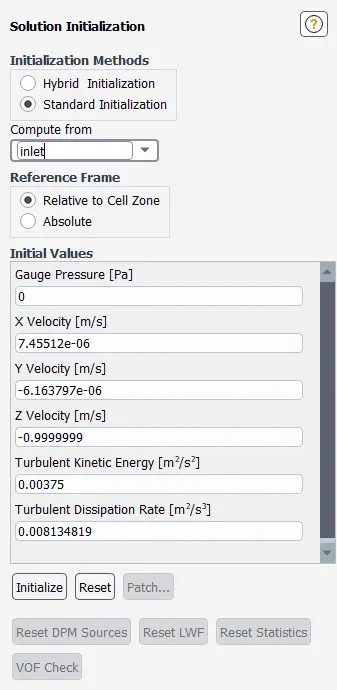
- Run the simulation for 600 iterations.
- export the particle history data and save it.
Post Processing
- select the wall surface and enable it and under rendering set the transperancy accordingly.
- import the FLUENT particle track file.
- under FLUENT pt for anthracite, set the max number of particle tracked to 100, under geometry option.
- and under colour option colour it as anthracite particle time variable.
- then create an animation for the same by using the animation option and save the file as .mpeg4 file with high resolutions.
Observation:
Case - 1.1 (particle velocity = 5m/s, particle size =5 um)
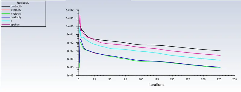
Residuals:
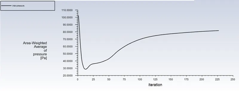
Total Pressure (inlet):
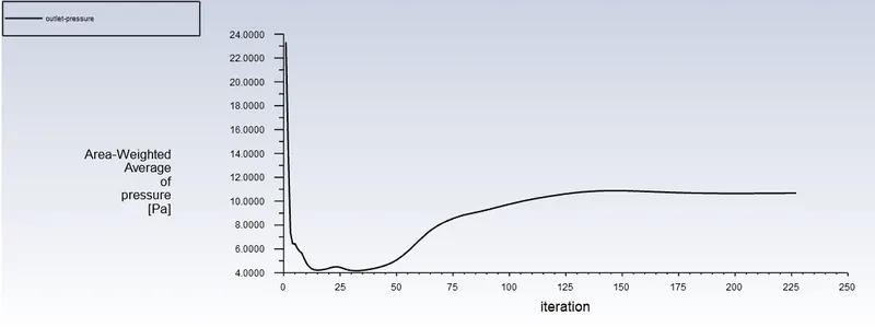
Total Pressure (outlet):
Pressure Drop:
Total pressure drop= total inlet pressure - total outlet pressure = 81.67 -10.67 = 71 Pa
Cyclone Separation Efficiency:
separation efficiency= number of particles trapped/ number of particles tracked = 288/288 = 1
Animation link:
https://drive.google.com/file/d/1sGwOiSHWFj2Q_YSY-iHIx7hWGnRfTWwB/view?usp=sharing
Case - 1.2 (particle velocity = 3m/s, particle size =5 um)
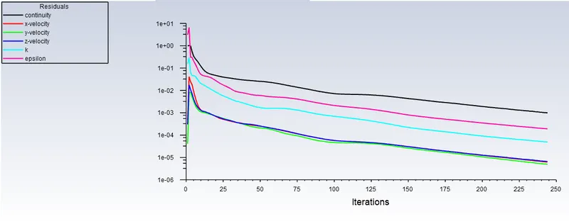
Residuals:
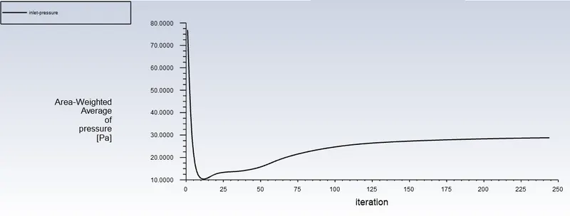
Total Pressure (inlet):
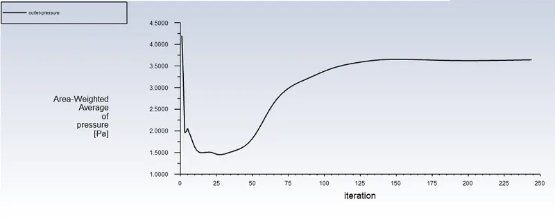
Total Pressure (outlet):
Pressure Drop:
Total pressure drop= total inlet pressure - total outlet pressure = 28.77-3.64 = 25.13 Pa
Cyclone Efficiency:
separation efficiency= number of particles trapped / number of particles tracked = 232/288 = 0.80
Animation link:
https://drive.google.com/file/d/1FLDnvEul4hU75-1sy6Y1nM-SLoIHTmKz/view?usp=sharing
Case - 1.3 (particle velocity = 1m/s, particle size =5 um)
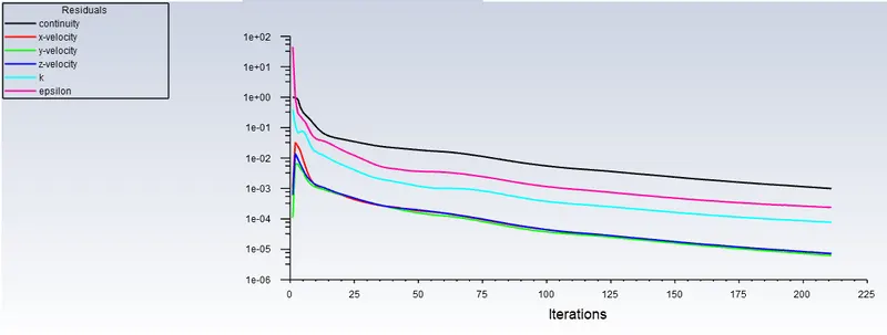
Residuals:
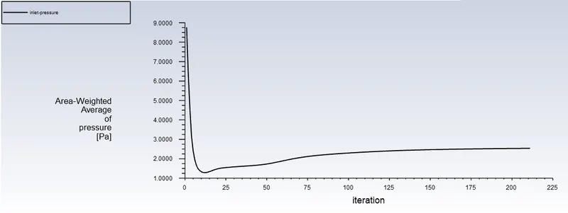
Total Pressure (inlet):
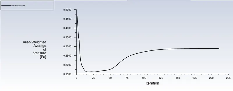
Total Pressure (outlet):
Pressure Drop:
Total pressure drop = total inlet pressure - total outlet pressure = 2.53-0.28 = 2.25 Pa
Cyclone Efficiency:
separation efficiency = number of particles trapped / number of particles tracked = 6/288 = 0.02
Animation link:
https://drive.google.com/file/d/1FDugNlL1xL2G-PMn3WNmUohbgAqdtgM6/view?usp=sharing
Case - 2.1 (particle velocity = 3m/s, particle size =5 um) (results are same as case 1.2)
Residuals:
Total Pressure (inlet):
Total Pressure (outlet):
Pressure Drop:
Total pressure drop= total inlet pressure - total outlet pressure = 28.77-3.64 = 25.13 Pa
Cyclone Efficiency:
separation efficiency= number of particles trapped / number of particles tracked = 232/288 = 0.80
Animation link:
https://drive.google.com/file/d/1FLDnvEul4hU75-1sy6Y1nM-SLoIHTmKz/view?usp=sharing
Case - 2.2 (particle velocity = 3m/s, particle size =2.5 um)
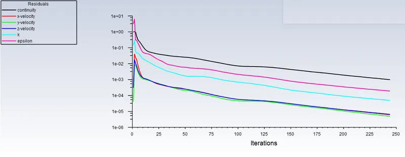
Residuals:
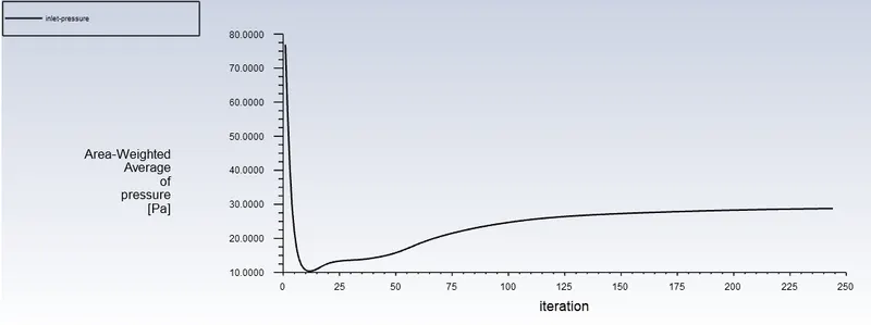
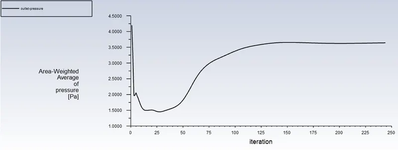
Total Pressure (inlet):
Total Pressure (outlet):
Pressure Drop:
Total pressure drop = total inlet pressure - total outlet pressure = 28.77-3.64 = 25.13 Pa
Cyclone Efficiency:
separation efficiency = number of particles trapped / number of particles tracked = 170/288 = 0.59
Animation link:
https://drive.google.com/file/d/1ylCxY_LAg6orUoE1ozDn_CmQtrBBIRtq/view?usp=sharing
Case - 2.3 (particle velocity = 3m/s, particle size =1 um)
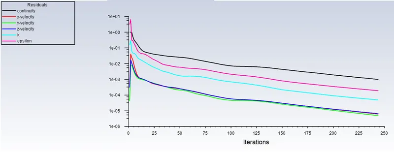
Residuals:
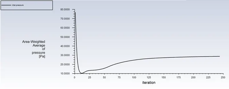
Total Pressure (inlet):
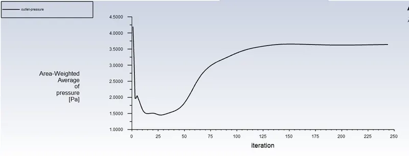
Total Pressure (outlet):
Pressure Drop:
Total pressure drop = total inlet pressure - total outlet pressure = 28.77-3.64 = 25.13 Pa
Cyclone Efficiency:
separation efficiency = number of particles trapped / number of particles tracked = 26/288 = 0.09
Animation link:
https://drive.google.com/file/d/1Ncv2hpULGLRo2d4cpqFIbNEgZTGZ59N3/view?usp=sharing
Inference:
- Pressure drop across inlet and outlet of cyclone separator, increases on increase in inlet velocity.
- Separation efficiency increases with increase in inlet velocity for a given particle size.
- Separation efficiency decreases with decrease in size of a given particle for fixed inlet velocity.
- Cartesian method of meshing could not produce some parts of geometry which could have led to errors in the results, hence it was avoided. And the option of cutcell method was not available in the latest student version of ansys hence could not be used.
Conclusion:
- A steady state analysis on a cyclone separator was performed and the separation efficiency and pressure drop was calculated.