Week 9- Unsteady moving zones Approach
AIM:
- To simulate a generic turbomachinery component using the Moving Mesh method in the transient state at 300 rpm using appropriate time steps to understand the flow physics.
- Generate an animation file for the rotation.
THEORY:
Moving Mesh Approach:
The moving mesh approach is used only for the unsteady phenomenon like,
- Vortex-induced flow.
- Interaction of vortex with bodies.
In Moving Mesh Approach,
- Mesh is moving.
- Topology of mesh changes with time.
- Control volume changes as mesh changes.
- It is an unsteady phenomenon.
PROCEDURE:
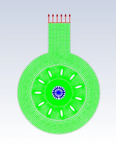
setp-1 Import mesh file
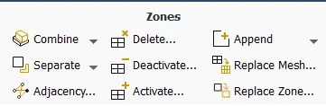
step-2 Append different mesh zones
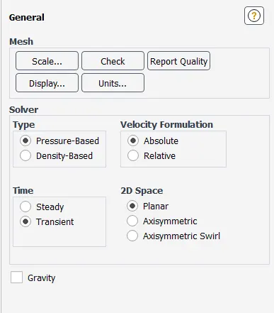
step-3 General Settings
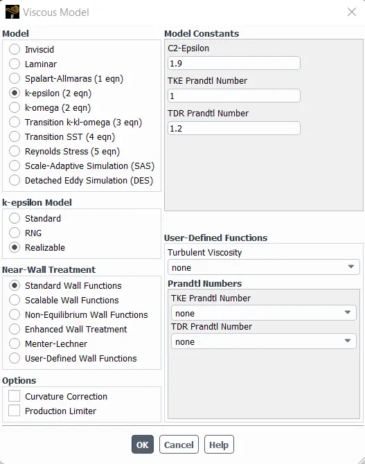
step-4 Viscous Model
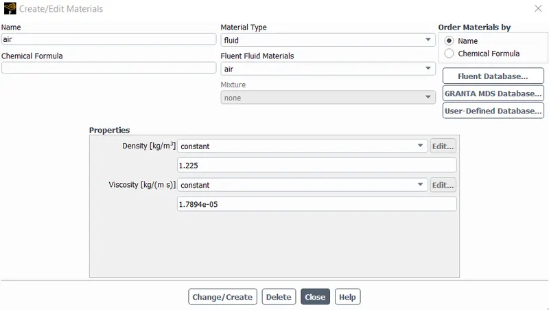
step-5 Material Selection
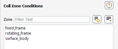
step-6 Cell Zones
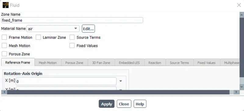
step-7 fixed frame
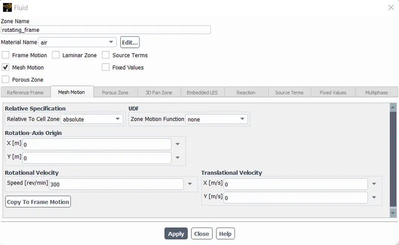
step-8 rotating frame
step-9 surface body
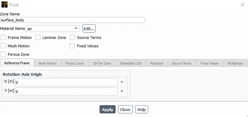
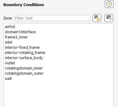
step-10 Boundary conditions
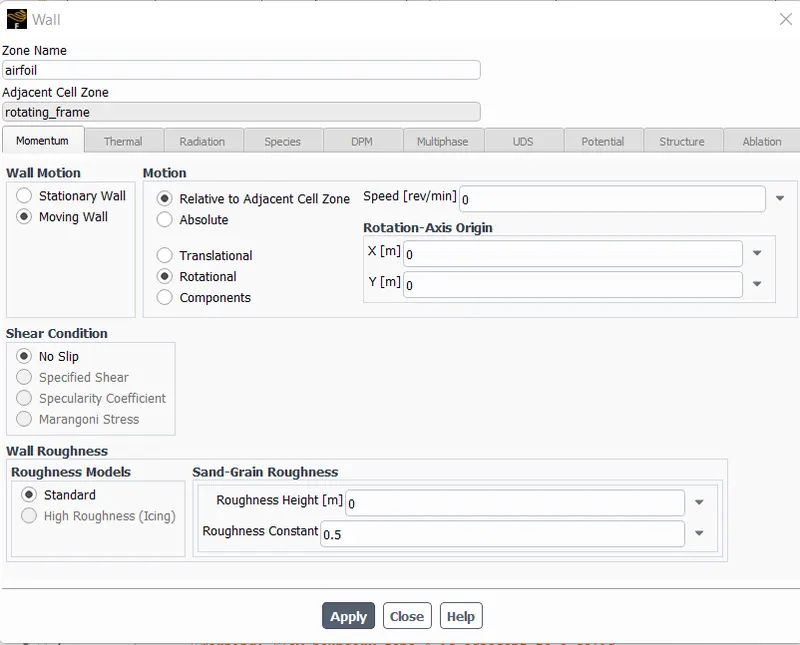
step-11 Airfoil boundary conditions
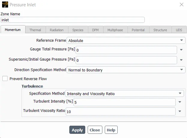
step-12 inlet B.C.
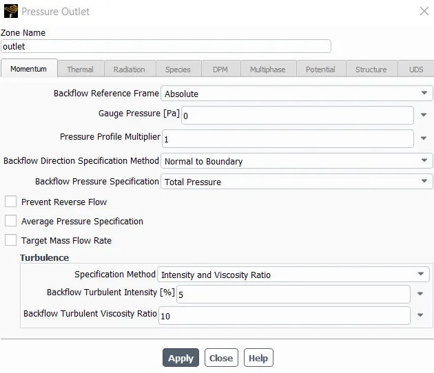
step-13 Outlet B.C.
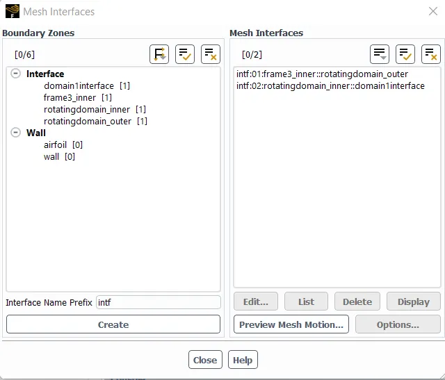
step-14 Defining interface
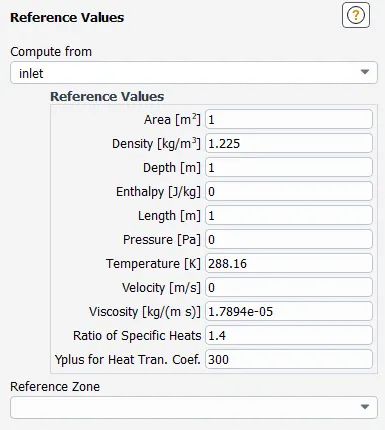
step-15 Reference values
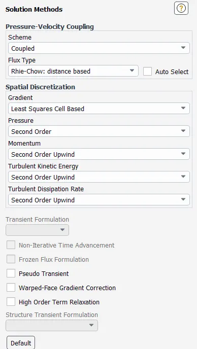
step-16 Solution Method
step-17 Solution Control
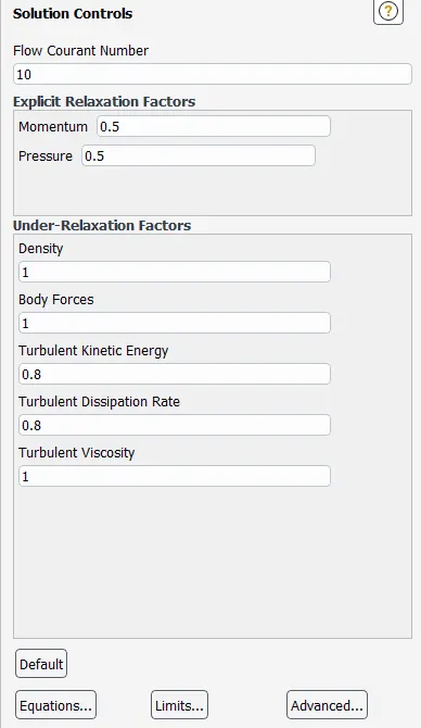
step-18 Flux report definition
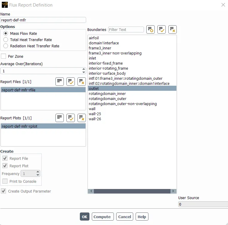
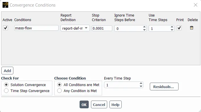
step-19 MFR Convergence condition
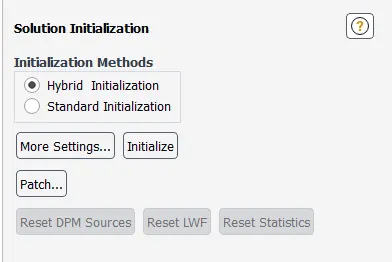
step-20 initialiazation
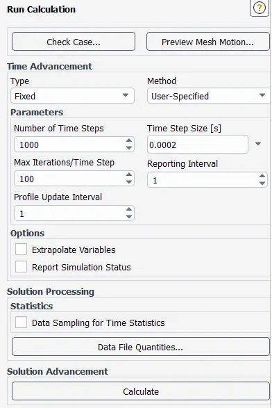
step-21 Time step calculation and running calculation
For timestep we use the formula,
rotational velocity = 300 rpm
angular velocity = (2 x pi x N) / 60
Time period = 60/ N
T = 0.2
to achieve this time period within 1000 timesteps we use
0.2/ 1000 = 0.0002.
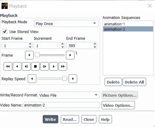
step-27 saving animation
results:
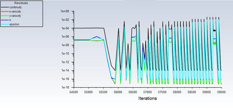
residuals:
Plots:
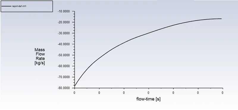
Mass Flow Rate:
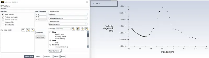
velocity:
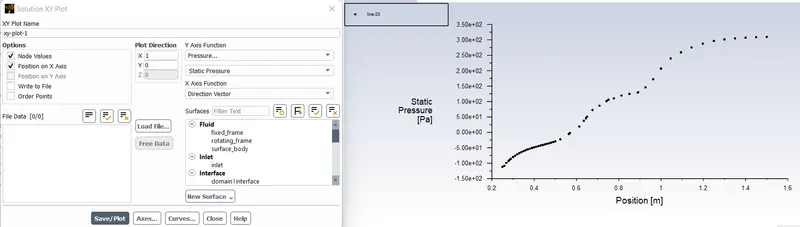
pressure:
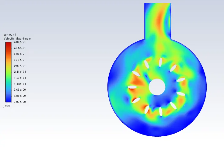
contour:
Velocity:
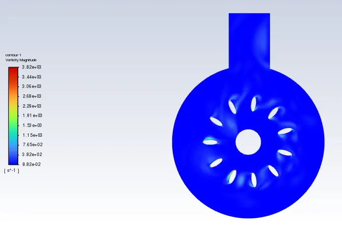
Vorticity:
Pressure:
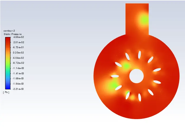
Link to animation:
Velocity Contour Animation:
animation-1.mp4 - Google Drive
Pressure Contour Animation:
animation-2.mp4 - Google Drive