Week 3:- BiW Fixture Design Methodologies Challenges
What is Design Methodology?
Answer:
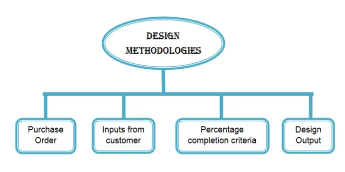
In this methodology, we investigate how we go about creating a design and we learn about three different design methods. One of the things we take care of is structuring or design tree, so we'll be learning how to do that as well as how to name certain components, assemblies, or parts of assemblies in a way that is both easy to read and understand.
Design techniques are simply the procedures used when conceptualising a fixture design. The many design methodology stages include:
- Purchase order.
- Inputs from customers.
- Percentage of completion criteria.
- Design outputs.
-
Purchase Order: A purchase order is a document issued by a buyer to a seller, formally requesting the purchase of goods or services. In the context of design, a purchase order represents the stage where the design process is initiated by a formal request from the customer or client to design a fixture. The purchase order typically includes information such as the desired specifications, quantity, delivery dates, and any other contractual terms.
-
Inputs from Customers: Inputs from customers play a crucial role in the design process. These inputs are the requirements, preferences, and expectations expressed by the customers regarding the fixture design. It can include factors such as functionality, aesthetics, size, materials, performance criteria, environmental considerations, and any specific industry standards or regulations. Gathering and understanding these inputs is essential for designing a fixture that meets the customers' needs and provides a satisfactory solution.
-
Percentage of Completion Criteria: Percentage of completion criteria is a measure used to track and evaluate the progress of a design project. It indicates the degree of completion at different stages of the design process. This criterion can be based on various factors, such as the completion of design milestones, the number of design iterations, or the fulfillment of specific design requirements. It helps assess how much of the overall design work has been accomplished and provides a sense of progress and timeline for the project.
-
Design Outputs: Design outputs refer to the tangible outcomes or deliverables generated during the design process. These outputs can include various elements, such as:
- Concept sketches or drawings: Initial visual representations of design ideas and concepts.
- CAD models: Detailed computer-generated models that represent the design in three dimensions.
- Technical specifications: Detailed documentation specifying dimensions, materials, manufacturing processes, and other relevant design details.
- Prototypes: Physical models or samples of the fixture design, created to verify functionality and aesthetics before full-scale production.
- Design documentation: Comprehensive documentation that captures all design-related information, including drawings, specifications, instructions, and any relevant calculations or analysis.
What are the inputs required from the customer to start designing a Fixture?
Answer:
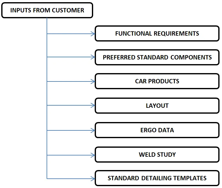
To start designing a fixture, the following inputs from the customer are typically required:
-
Functional Requirements: Understanding the functional requirements of the fixture is crucial. These requirements describe what the fixture needs to do and the purpose it serves. For example, if it is a lighting fixture, the customer may specify the desired light output, beam angle, color temperature, and any specific features or functionalities required.
-
Specifications and Dimensions: The customer should provide specific specifications and dimensions for the fixture. This includes information about the desired size, shape, weight, and any spatial constraints or limitations that need to be considered during the design process.
-
Aesthetics and Design Preferences: The customer's aesthetic preferences and design expectations play a significant role. They may have a particular style, color scheme, or visual theme in mind for the fixture. Understanding their preferences helps in creating a design that aligns with their desired aesthetics.
-
Environmental and Usage Considerations: Customers may have specific environmental considerations or usage requirements. For instance, if the fixture will be used in outdoor environments, it may need to be weatherproof or resistant to corrosion. Understanding the operating conditions and any potential challenges the fixture may face helps in designing a suitable solution.
-
Industry Standards and Regulations: Depending on the industry or application, there may be specific standards, regulations, or certifications that the fixture needs to comply with. The customer should provide information regarding any relevant standards or regulatory requirements that need to be considered during the design process.
-
Budget and Cost Constraints: Knowing the customer's budget and cost constraints is essential for designing a fixture that meets their requirements while staying within the specified budget. This allows the design team to make informed decisions regarding material choices, manufacturing processes, and overall design complexity.
-
Timeline and Delivery Requirements: Customers may have specific timelines and delivery requirements for the fixture. Understanding these constraints helps in planning the design process and ensuring that the design can be completed within the desired timeframe.
It is important for designers to have open and effective communication channels with customers to gather these inputs accurately. This ensures that the design aligns with the customer's expectations and requirements from the early stages of the design process.
What is the input we get from "Car Products"?
Answer:
When obtaining inputs from car products for fixture design, the following information is typically included:
-
GD&T (Geometric Dimensioning and Tolerancing): GD&T is a symbolic language used to communicate and specify the geometric and dimensional requirements of car products. The customer may provide GD&T specifications for the components that the fixture will interact with or support. This information ensures that the fixture design aligns with the specified tolerances and dimensional requirements.
-
Part Lists: Part lists provide a comprehensive inventory of the car products or components that the fixture will interface with. These lists specify the part numbers, descriptions, quantities, and any other relevant information needed to identify and incorporate the required components into the fixture design.
-
3D CAD File: A 3D CAD (Computer-Aided Design) file of the car product or component is a digital representation that contains detailed geometric information. The customer may provide the CAD file for the specific car product to ensure accurate integration and alignment with the fixture design.
-
Clamp Plan: A clamp plan illustrates the locations and methods for securing or clamping the car products or components during the assembly process. This plan outlines the specific clamping points, fixtures, or devices that need to be incorporated into the fixture design to properly hold the components in place during assembly or testing.
-
Product Assembly Process Sheet: The product assembly process sheet provides step-by-step instructions or guidelines for assembling the car products or components. It outlines the sequence, tools, techniques, and any specific considerations required during the assembly process. This information helps in designing a fixture that facilitates efficient and error-free assembly.
By incorporating these inputs into the fixture design process, designers can ensure that the fixture is compatible with the car products, aligns with the specified tolerances, facilitates proper clamping and assembly, and seamlessly integrates with the overall production process.
What is the Clamp plan?
Answer:
A clamp plan is a document or drawing that outlines the locations and methods for securing or clamping components during assembly or testing processes. It provides instructions on how to properly hold and position parts to ensure accurate and consistent assembly or testing results.
The clamp plan typically includes the following information:
1. Clamping Points: It specifies the specific points on the component where clamping is required. These points are strategically chosen to ensure stability and proper alignment during the assembly or testing process.
2. Clamping Devices or Fixtures: The plan identifies the clamping devices or fixtures that should be used to secure the components. These can include various types of clamps, jigs, holding fixtures, or specialized tools designed to provide adequate support and stability during the process.
3. Clamping Sequence: The plan outlines the recommended sequence for applying the clamps. This sequence ensures that the components are securely held in the correct position, preventing any movement or misalignment during assembly or testing.
4. Clamping Force or Pressure: In some cases, the clamp plan may also specify the required clamping force or pressure to be applied. This ensures that the components are held firmly but without causing damage or deformation.
5. Clearances and Access: The plan takes into account any necessary clearances or access requirements for other assembly or testing operations. It ensures that the clamping devices or fixtures do not interfere with other components or processes.
By providing a clear clamp plan, designers and assembly technicians can ensure consistent and accurate positioning of components, minimize errors or misalignments, and facilitate efficient assembly or testing processes. The clamp plan acts as a guideline to ensure that the clamping method used in the fixture design properly supports the specific requirements of the components being assembled or tested.
What is the purpose of a Layout?
Answer:
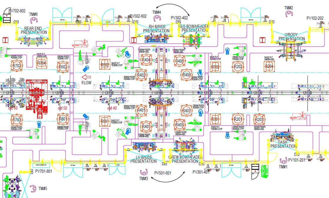
The purpose of the layout in the context of fixture and robot placement within an assembly line is as follows:
1. Flow of Parts: The layout provides information about the flow of parts within the assembly line. It shows the sequence in which components or products move from one station to another, indicating the logical progression of the assembly process. This helps in organizing and optimizing the workflow and ensures efficient movement of parts.
2. Station Pitch: The layout defines the station pitch, which refers to the distance or spacing between consecutive workstations or stations along the assembly line. It determines the physical arrangement and positioning of fixtures and robots, ensuring proper allocation of space and allowing for smooth movement and operation.
3. Robot Stations: The layout identifies the specific locations or stations where robots are assigned to perform tasks or operations. It indicates the positions where robots are stationed to carry out their designated functions, such as handling components, performing assembly tasks, or executing specific operations. This helps in optimizing the utilization of robots and their integration into the assembly process.
4. Sub-assembly Link: The layout showcases the link or connection between different sub-assemblies within the assembly line. It identifies the points where sub-assemblies come together or interface with one another to form the final product. This facilitates the coordination and synchronization of different assembly processes and ensures a smooth transition between sub-assemblies.
Overall, the layout provides a visual representation of the entire assembly plan, depicting the arrangement of fixtures, robots, workstations, and the flow of parts. It enables stakeholders to understand and analyze the assembly process, identify potential bottlenecks or inefficiencies, and make informed decisions to optimize productivity and efficiency.
What is Ergo data?
Answer:
In the context of BIW (Body-in-White) fixtures, ergo data refers to specific information and considerations related to ergonomic factors in the design of fixtures used in the automotive manufacturing process. BIW fixtures are used to hold and position vehicle body components during assembly and welding.
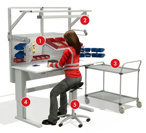
Ergo data for BIW fixtures typically includes:
1. Ergonomic Reach: This refers to the range of motion and reach capabilities of assembly operators. Ergonomic reach data helps determine the optimal positioning of components within the fixture to ensure that operators can access and manipulate them comfortably and efficiently.
2. Body Posture and Comfort: Ergo data takes into account the ergonomic considerations for the operator's body posture and comfort during the assembly process. It includes factors such as seating position, arm and hand positions, and body support to minimize fatigue, strain, and potential injuries.
3. Anthropometric Data: Anthropometric data, which includes measurements of body dimensions and proportions, is considered when designing BIW fixtures. This data helps ensure that the fixture dimensions and clearances are suitable for a diverse range of operators, accommodating variations in height, reach, and body size.
4. Force Requirements: Ergo data also considers the force requirements for handling and manipulating vehicle body components within the fixture. This includes assessing the force needed for tasks such as lifting, aligning, and fastening components during the assembly process.
By incorporating ergo data into the design of BIW fixtures, manufacturers can optimize the ergonomics of the assembly process. This leads to improved operator comfort, safety, and productivity, ultimately enhancing the overall efficiency and quality of the automotive manufacturing process.
What do you understand by Weld study?
Answer:
A weld study, also known as a welding study or weld analysis, is a process that involves the examination and evaluation of weld joints to assess their quality, integrity, and performance. It is a systematic approach to analyzing and optimizing welding processes to ensure that welds meet the required standards and specifications.
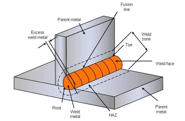
The purpose of a weld study is to identify and address any potential issues or concerns related to the weld joints, such as strength, durability, distortion, or defects. The study helps in determining the optimal welding parameters, techniques, and procedures to achieve high-quality welds that meet the desired criteria.
Key aspects of a weld study include:
1. Welding Parameters: The study involves analyzing and optimizing the welding parameters, such as voltage, current, welding speed, electrode composition, shielding gas, and preheat temperature. These parameters have a significant impact on the quality and characteristics of the weld joint.
2. Welding Technique: Different welding techniques, such as arc welding, resistance welding, or laser welding, may be employed depending on the specific application. The study assesses the suitability and effectiveness of the chosen welding technique for achieving the desired weld quality and properties.
3. Weld Defect Analysis: The weld study involves examining the weld joints for any defects or imperfections, such as cracks, porosity, incomplete fusion, or excessive spatter. Defect analysis helps identify the root causes of these issues and allows for corrective actions to be implemented to eliminate or minimize defects.
4. Strength and Durability Evaluation: The study includes testing and evaluating the strength and durability of the welds. This may involve destructive testing, such as tensile testing or bend testing, to assess the mechanical properties of the weld joint and ensure that it meets the required strength and performance criteria.
5. Distortion Control: Welding processes can often cause distortion or deformation of the workpiece or assembly. The weld study examines the potential for distortion and explores techniques or measures to control and minimize it, ensuring dimensional accuracy and proper fit-up of components.
By conducting a weld study, engineers and welding professionals can optimize the welding process, improve weld quality, and ensure that the weld joints meet the specified requirements. The study helps in identifying and rectifying any potential issues or deficiencies, ultimately leading to reliable and high-quality welds in various applications and industries.
What are the criteria for percentage completion in the designing stage? Explain it in detail
Answer:
When designing and shipping welding equipment, the % completion standards are followed. This percentage completion criterion is used to determine whether the project is on schedule for delivery to the client, as promised. Additionally, it enables us to recognise the project's stages, such as how much of it has already been finished and which stages still need to be finished in order for the project to be finished on schedule. To determine the percentage of the job that has been completed, the percentage completion criteria is broken down into four steps.
The four stages of the percentage completion criteria in fixture design can be summarized as follows:
1. Input & Concept Design: In this stage, the initial inputs and requirements from the customer are gathered and analyzed. The design team works on developing the concept design for the fixture based on these inputs. This includes understanding the functional requirements, preferred components, layout considerations, and other relevant factors.
2. Concept Approval & Simulation Check: Once the concept design is developed, it goes through a review and approval process. The design team presents the concept to stakeholders for evaluation and feedback. At this stage, simulation checks may be conducted to assess the feasibility, performance, and functionality of the fixture design. This helps in identifying any potential issues or areas for improvement.
3. Design Freezing & Detailing: After the concept is approved and simulation checks are completed, the design is frozen, meaning that no major changes or modifications are made to the overall design concept. The detailed design process begins, where the fixture design is further refined, specifying the dimensions, materials, components, and other detailed aspects. This stage involves creating detailed engineering drawings, specifying manufacturing processes, and selecting appropriate manufacturing techniques.
4. Check & Final Dispatch: The final stage involves conducting thorough checks and inspections to ensure that the fixture design meets all the specified requirements and quality standards. This includes reviewing the design documentation, performing design reviews, and conducting functional and performance tests. Once the checks are completed and the fixture design is deemed satisfactory, it is ready for final dispatch or delivery to the customer.
These four stages help ensure a systematic and structured approach to fixture design, from the initial concept to the final product. The percentage completion criteria can be used to track the progress of the design process and provide a measure of how far the design has advanced through these stages.
Brief about "Output" in design?
Answer:
Design Output consist of lots of data like 3D and 2D documents, VMC IGS files, STEP files, gas-cut or laser-cut files in dwg format and BOM, etc. We have to give these data to our customer as design output. The basic output are 3D models and 2D drawing of fixture. Output are classified as below:
1. Unitized Tools: Unitized tools refer to fixtures that are designed as a complete, integrated unit. They are typically used for specific tasks or operations and are self-contained. The design output for unitized tools includes 3D models and 2D drawings of the fixture. These models and drawings provide a detailed representation of the fixture's design, dimensions, and assembly instructions. Additionally, a Bill of Materials (BOM) is also included, which lists all the components and materials required for building the unitized tool.
2. Non-unitized Tools: Non-unitized tools refer to fixtures that are designed as a collection of separate components or modules. These fixtures offer flexibility and can be customized or reconfigured for different purposes. The design output for non-unitized tools includes 3D models and 2D drawings of the individual components. These models and drawings provide detailed information about the dimensions, features, and assembly instructions for each component. Additionally, other files such as VMC IGS files, STEP files, gas-cut or laser-cut files in DWG format may be included as needed, depending on the manufacturing and assembly processes involved.
In summary, the design output for unitized tools primarily includes 3D models, 2D drawings, and a BOM, while the design output for non-unitized tools includes 3D models, 2D drawings of individual components, and potentially other files specific to manufacturing or assembly processes. These design outputs provide the necessary information for the customer to understand, manufacture, and assemble the fixtures accurately according to the design specifications.
What do you understand by structuring a design tree? How does it reduce errors during the design process?
Answer:
Structuring a design tree involves organizing the components, features, and operations of a design in a hierarchical manner using a tree-like structure. It helps in visualizing the relationships and dependencies between different design elements.
By structuring a design tree, errors during the design process can be reduced through the following:
1. Organization and Clarity: A well-structured design tree provides a clear and organized representation of the design's components and operations. It enables designers to easily understand and navigate the design hierarchy, reducing the chances of overlooking or missing important elements.
2. Modularity and Editability: Design trees allow for efficient modification and editing of the design. Each element can be individually accessed and modified, keeping changes localized and reducing the risk of unintended consequences. It ensures that modifications can be made accurately and consistently.
3. Design Intent Preservation: The design tree captures the design history and intent, maintaining a record of modifications and changes. Designers can refer back to previous versions or states, aiding in error detection and preventing mistakes caused by overlooking changes made during the design process.
4. Visual Feedback and Validation: Design trees provide visual feedback on the design structure, dependencies, and any errors or warnings associated with the design elements. Design software often highlights conflicts or inconsistencies, helping designers identify and rectify errors promptly.
Overall, structuring a design tree enhances the organization, modularity, and traceability of a design. It promotes better design management, reduces the likelihood of errors, and improves the overall efficiency and accuracy of the design process.
What are Units? Mention 5 types of units.
Answer:
In the context of fixture design, units refer to the individual components or modules that make up a fixture. These units are designed to perform specific functions and contribute to the overall functionality of the fixture. Here are five types of units commonly used in fixture design:
1. Fixed Pin Units: Fixed pin units consist of fixed pins or locators that are used to accurately position and locate a workpiece or component in the fixture. These pins are designed to provide stable and repeatable alignment during the assembly or manufacturing process.
2. Retract Pin Units: Retract pin units include retractable pins or locators that can be retracted or released when required. These pins are used to hold and position the workpiece during specific operations and can be retracted to allow for the removal or repositioning of the workpiece.
3. Rough Locator Units: Rough locator units are designed to quickly and roughly position or locate the workpiece in the fixture. These units provide initial alignment and rough positioning before more precise locators or clamps are engaged for accurate and secure fixation.
4. Sensor Units: Sensor units consist of sensors or measurement devices integrated into the fixture. These sensors are used to detect, measure, or verify various parameters such as dimensions, positions, or alignment of the workpiece. They play a crucial role in quality control and ensuring accurate assembly or manufacturing processes.
5. Base Units: Base units form the foundation or primary structure of the fixture. They provide stability and support for other units and components of the fixture. Base units are typically designed to be rigid, durable, and capable of withstanding the forces and loads experienced during the assembly or manufacturing process.
These five types of units represent some common examples found in fixture design, each serving a specific purpose in holding, positioning, and aligning the workpiece to enable accurate and efficient assembly or manufacturing processes.
Describe Fixed Pin units & their purpose?
Answer:
Fixed pin units in fixture design refer to components or modules that include fixed pins or locators. These fixed pins are designed to provide precise and stable positioning and alignment of the workpiece within the fixture. They play a crucial role in ensuring accurate assembly or manufacturing processes.
The purpose of fixed pin units in fixtures is to:
1. Establish Alignment: Fixed pins are used to establish the correct alignment and position of the workpiece within the fixture. They serve as reference points to ensure that the workpiece is correctly positioned for subsequent operations.
2. Maintain Repeatability: Fixed pins provide consistent and repeatable positioning of the workpiece in the fixture. This ensures that the workpiece is held in the same position for each iteration of the assembly or manufacturing process, resulting in consistent quality and dimensional accuracy.
3. Prevent Movement: The fixed pins are designed to securely hold the workpiece in place, preventing any unintended movement or shifting during the assembly or manufacturing process. This stability is essential for maintaining the integrity and precision of the workpiece alignment.
4. Enable Interchangeability: Fixed pin units allow for interchangeable use of different workpieces with the same fixture. By adjusting the positions of the fixed pins, the fixture can accommodate workpieces of varying sizes or configurations, providing flexibility in production.
5. Simplify Assembly: Fixed pin units simplify the assembly process by providing clear reference points for operators. They eliminate the need for manual measurements and alignment, reducing human error and increasing efficiency.
Overall, fixed pin units in fixtures contribute to accurate and repeatable positioning of the workpiece, ensuring that subsequent operations are performed precisely and consistently. They play a vital role in maintaining dimensional accuracy, reducing errors, and improving the overall quality of the assembly or manufacturing process.
What are the different parts of a fixed unit?
Answer:
The different parts of the fixed pin units in fixture design include:
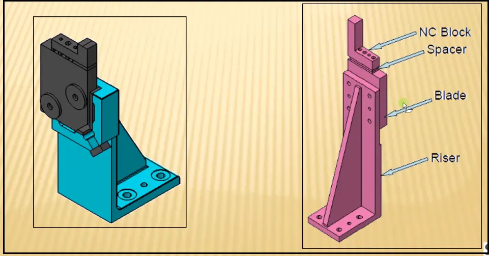
1. Pin: The pin is the main component of the fixed pin unit. It is a cylindrical or conical element that is inserted into the fixture and serves as a locator or reference point for the workpiece. The pin is typically made of hardened steel or another durable material to withstand the forces and loads during the assembly process.
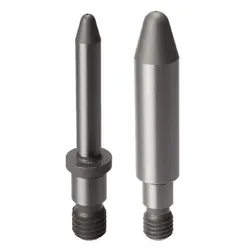
2. Pin Retainer: The pin retainer is a component that holds the pin in place within the fixture. It ensures that the pin remains securely positioned and prevents it from dislodging or shifting during operation. The pin retainer may use various mechanisms such as screws, clamps, or spring-loaded mechanisms to secure the pin in place.
3. Shims: Shims are thin, flat components that are placed between the pin and the workpiece or between the pin and the fixture itself. They are used to fine-tune the height or position of the pin, allowing for precise adjustment and alignment of the workpiece. Shims come in different thicknesses and materials to accommodate specific requirements.
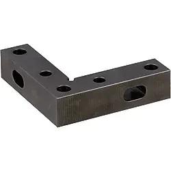
4. Blade: The blade is a part that extends from the pin or pin retainer and provides additional support or stability to the workpiece. It helps prevent lateral movement or rotation of the workpiece during the assembly process. Blades can have different shapes and configurations depending on the specific fixture design and requirements.
5. Riser: The riser is a component that elevates the fixed pin unit from the fixture base or platform. It provides additional clearance or height to accommodate the workpiece or to align with other components in the fixture assembly. The riser may be adjustable or fixed, depending on the design and requirements of the fixture.
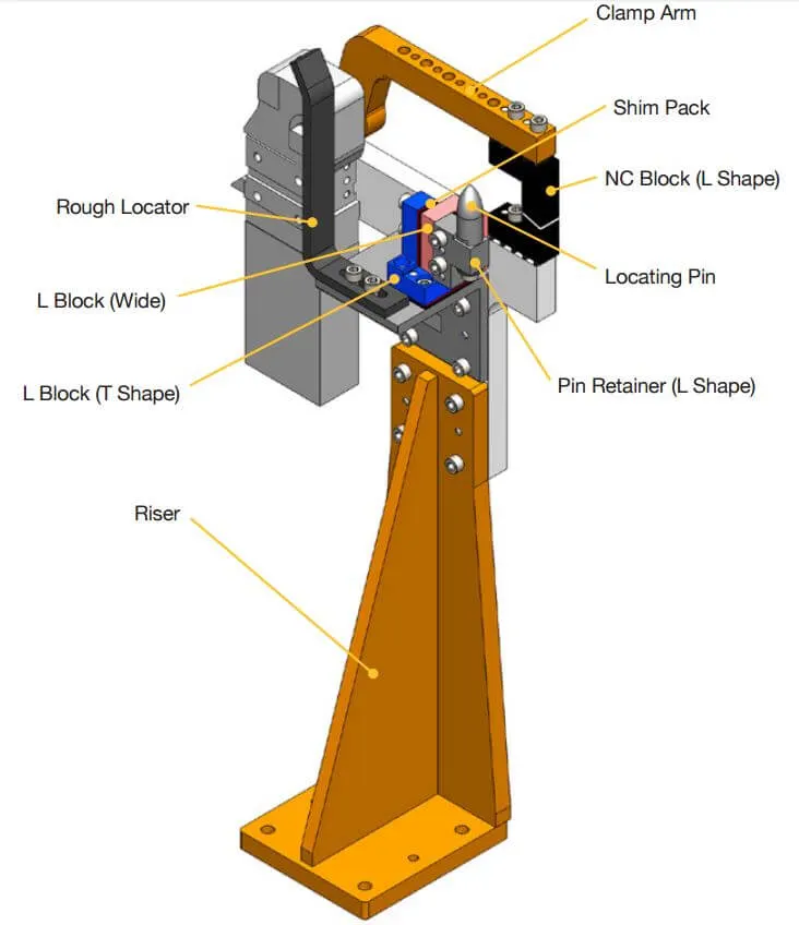
These different parts of the fixed pin units work together to establish accurate and stable positioning of the workpiece within the fixture. They contribute to the precision and repeatability of the assembly process, ensuring consistent and reliable results.
What is the purpose of making a Rest unit & describe its parts?
Answer:
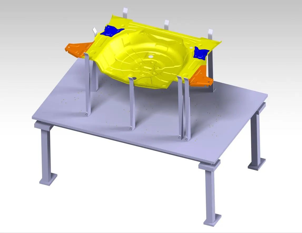
In the context of BIW (Body-in-White) fixture design, a Rest unit serves the purpose of supporting and stabilizing the workpiece or specific components during the assembly or manufacturing process. It provides a secure resting position to prevent unwanted movement, distortion, or damage to the workpiece. The Rest unit typically consists of several parts that work together to achieve its intended function. These parts may include:
1. Rest Pad: The Rest pad is the main component of the Rest unit. It is a flat or contoured surface that comes in direct contact with the workpiece. The Rest pad is designed to provide support and distribute the load evenly, minimizing any potential deformation or damage to the workpiece.
2. Mounting Bracket: The Mounting bracket is used to attach the Rest pad to the fixture. It provides a secure connection and allows for adjustability in terms of height, angle, or position. The Mounting bracket may have various mechanisms such as clamps, screws, or quick-release mechanisms to securely hold the Rest pad in place.
3. Adjustable Arms: In some Rest units, adjustable arms are included to provide additional flexibility. These arms can be extended or retracted, allowing for customization of the Rest unit based on the specific workpiece dimensions or geometry. The adjustable arms provide adaptability and help ensure optimal contact and support.
4. Locking Mechanism: The Rest unit may incorporate a locking mechanism to securely hold the Rest pad in the desired position. This ensures that the Rest pad remains fixed during the assembly process, providing consistent support to the workpiece. The locking mechanism can be operated manually or through a controlled mechanism, depending on the specific fixture design.
5. Height Adjustment Mechanism: Some Rest units may include a height adjustment mechanism to accommodate workpieces of different sizes or heights. This mechanism allows for precise vertical positioning of the Rest pad, ensuring optimal support and alignment with the workpiece.
By utilizing a Rest unit in BIW fixture design, it becomes possible to maintain the stability and integrity of the workpiece during assembly or manufacturing processes. The Rest pad, mounting bracket, adjustable arms, locking mechanism, and height adjustment mechanism work together to provide secure support, minimize distortion, and prevent damage to the workpiece.
What are the basic fundamentals to design a Sensor unit?
Answer:
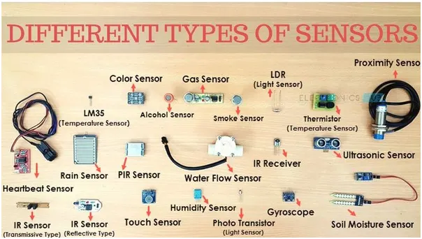
The basic fundamentals to design a sensor unit include:
1. Purpose and Measurement Requirement: Clearly define the purpose of the sensor unit and identify the specific parameters or variables that need to be measured.
2. Sensor Selection: Choose the appropriate sensor type based on the measurement requirements, considering factors such as accuracy, range, response time, and compatibility with the target application.
3. Mounting and Integration: Determine how the sensor will be mounted and integrated into the fixture design, ensuring proper positioning and alignment with the target measurement area.
4. Signal Processing: Incorporate suitable signal processing techniques to condition, amplify, filter, or digitize the sensor output for accurate and reliable measurement data.
5. Calibration: Ensure proper calibration of the sensor unit to establish accurate measurement references and compensate for any inherent errors or deviations.
6. Protection and Durability: Consider environmental factors and incorporate measures to protect the sensor unit from adverse conditions such as dust, moisture, temperature variations, or mechanical impacts.
7. Integration with Control System: Plan for seamless integration of the sensor unit with the overall control system, including appropriate communication protocols and interfaces.
8. Validation and Testing: Conduct thorough validation and testing to verify the sensor unit's performance, accuracy, and reliability under various operating conditions.
By adhering to these basic fundamentals, designers can develop sensor units that effectively measure the desired parameters, integrate well with the fixture design, and provide accurate data for process control and quality assurance.
What is a Rough locator unit & what are the basic fundamentals to consider while designing it?
Answer:
A Rough Locator unit in fixture design refers to a component or module that is used to quickly and roughly position or locate the workpiece in the fixture. It provides initial alignment before more precise locators or clamps are engaged for accurate and secure fixation. The purpose of a Rough Locator unit is to expedite the setup process and ensure approximate positioning of the workpiece before detailed adjustments are made.
The basic fundamentals to consider while designing a Rough Locator unit include:
1. Design Intent: Clearly define the intended purpose of the Rough Locator unit. Determine the level of rough positioning required and how it fits into the overall fixture design and assembly process.
2. Alignment Mechanism: Select an appropriate alignment mechanism that allows for quick and approximate positioning of the workpiece. This may include pins, guides, slots, or other mechanisms that enable swift and easy insertion or placement of the workpiece.
3. Stability and Support: Ensure that the Rough Locator unit provides adequate stability and support to prevent unintended movement or displacement of the workpiece during subsequent operations. Consider the forces and loads experienced during assembly or manufacturing processes and design the unit to withstand them.
4. Interchangeability: Design the Rough Locator unit to accommodate different workpiece sizes or configurations. It should allow for easy interchangeability and adjustment to handle a range of workpieces effectively.
5. Compatibility with Other Units: Consider the compatibility of the Rough Locator unit with other units or components in the fixture design. Ensure proper alignment and integration to achieve a cohesive and functional fixture assembly.
6. Ergonomics and Ease of Use: Design the Rough Locator unit with considerations for operator ergonomics and ease of use. Ensure that it facilitates quick and intuitive workpiece positioning without requiring excessive effort or complex adjustments.
7. Material Selection: Choose suitable materials for the Rough Locator unit that offer sufficient strength, durability, and dimensional stability. Consider factors such as wear resistance, corrosion resistance, and any specific environmental conditions in which the unit will operate.
8. Validation and Testing: Perform validation and testing of the Rough Locator unit to verify its effectiveness and functionality. Evaluate its performance in terms of rough positioning accuracy, repeatability, and reliability.
By considering these basic fundamentals during the design process, a Rough Locator unit can be developed to expedite workpiece setup, provide approximate alignment, and contribute to the overall efficiency and accuracy of the fixture assembly process.
What is a Base unit and describe it's parts?
Answer:
In fixture design, a Base unit refers to the foundational component that provides stability and support to the entire fixture assembly. It serves as the primary structure onto which other components and units are mounted or integrated. The Base unit is typically designed to withstand the forces, vibrations, and loads encountered during the assembly process.
The parts or components of a Base unit may vary depending on the specific fixture design, but some common elements include:
1. Base Plate: The Base plate is the main structural component of the Base unit. It is a flat, rigid plate usually made of high-quality steel or another durable material. The Base plate provides a stable and level surface for mounting other fixture components and supporting the workpiece.
2. Mounting Holes: The Base plate features drilled or machined mounting holes to allow for the attachment of other units, fixtures, or components. These holes are strategically positioned to ensure proper alignment and secure fastening of the various elements in the fixture assembly.
3. Mounting Rails or T-Slots: Some Base units may incorporate mounting rails or T-slots on the Base plate. These provide additional flexibility for attaching and adjusting other fixture components. Rails or T-slots allow for the easy movement and positioning of clamps, locators, sensors, or other units along the Base unit as needed.
4. Alignment Features: Base units may include alignment features such as dowel pins, slots, or alignment blocks. These features aid in the proper alignment and registration of the workpiece and other fixture components to ensure accurate and repeatable assembly processes.
5. Stiffeners or Bracing: To enhance the rigidity and stability of the Base unit, stiffeners or bracing may be incorporated. These structural reinforcements help minimize deflection or distortion of the Base unit under the applied forces, maintaining the overall integrity of the fixture assembly.
6. Leveling Feet: Base units often include adjustable leveling feet or pads. These allow for fine-tuning and leveling of the fixture assembly, compensating for any uneven or sloping surfaces in the assembly area. Leveling feet ensure stability and prevent any unintended movement or tilting during the assembly process.
The Base unit forms the solid foundation for the fixture design, providing stability, alignment, and support for the workpiece and other fixture components. Its design and construction are critical to the overall performance and functionality of the fixture assembly.
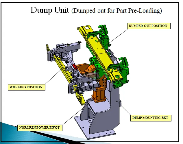
What is a Dump Unit and what are its functions?
Answer:
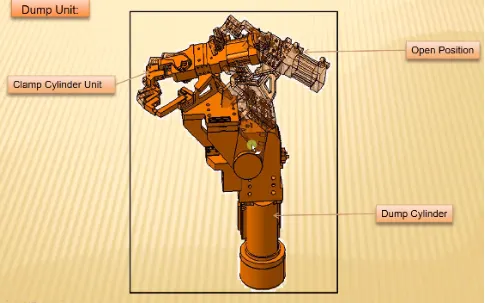
In fixture design, a Dump Unit refers to a component or mechanism that facilitates the controlled release or removal of a workpiece from the fixture after a specific operation or process is completed. Its primary function is to safely and efficiently eject or dump the workpiece from the fixture without causing any damage or interference.
The functions of a Dump Unit in fixture design include:
1. Workpiece Release: The Dump Unit allows for the smooth release or ejection of the workpiece from the fixture. It ensures that the workpiece is released without any obstructions or interference, preventing any potential damage or distortion.
2. Controlled Movement: The Dump Unit provides controlled movement to guide the workpiece out of the fixture. It may incorporate mechanisms such as slides, guides, or actuators to facilitate a controlled and precise motion during the ejection process.
3. Safety and Protection: The Dump Unit is designed to ensure the safety of both the workpiece and the operators. It prevents any sudden or uncontrolled movement of the workpiece, minimizing the risk of accidents or injuries during the ejection process.
4. Workpiece Orientation: Depending on the specific application, the Dump Unit may also be designed to orient the workpiece in a specific manner during the ejection process. This ensures that the workpiece is correctly positioned or oriented for further processing or handling.
5. Integration with Control System: The Dump Unit can be integrated into the overall control system of the fixture. It can be automated and synchronized with other components or operations, allowing for seamless and efficient ejection of the workpiece as part of the overall assembly or manufacturing process.
By incorporating a Dump Unit into the fixture design, manufacturers can ensure the safe and efficient removal of workpieces from the fixture, enabling smooth workflow and preventing any potential damage or hindrance in the production process.
What is a Slide unit? Mention where Slide units are commonly used.
Answer:
A Slide unit, in the context of fixture design, refers to a component or mechanism that enables linear movement of an object or fixture along a defined path. It typically consists of a sliding element, such as a ball bearing or roller, enclosed within a housing or track.
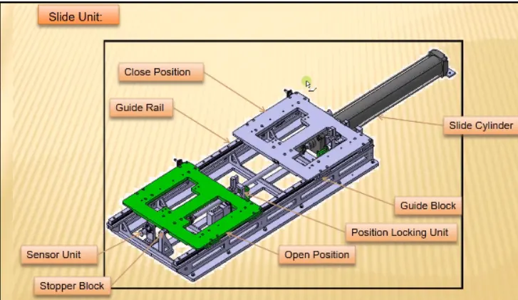
Slide units are commonly used in various industries and applications, including:
1. Manufacturing: They are used in fixture design for assembly lines, allowing smooth and controlled movement of workpieces during production processes.
2. Automation: Slide units are employed in automated systems, such as robotics and conveyor systems, to facilitate precise positioning and transfer of objects.
3. Tooling and machining: They are used in jigs and fixtures for machining operations, enabling accurate and repeatable movement of cutting tools or workpieces.
4. Inspection and testing: Slide units are utilized in fixtures for quality control and testing purposes, allowing the movement of test probes or measuring devices along specified paths.
5. Material handling: Slide units find application in material handling equipment, such as slides or guides for drawers, shelves, and sliding doors.
Overall, Slide units play a vital role in fixture design by providing reliable linear motion, enhancing efficiency, and ensuring proper alignment and positioning of components in various industrial processes.