Roof Design
ROOF DESIGN
Aim:
- The project's goal is to design the roof sheet metal in NX cad, as well as the front roof rail, rear roof rail, bow roof front, bow roof rear, and centre roof rail, which are all needed to construct a strong roof.
-
To determine the location of the bow roofs, conduct a curvature study on the roof and performance calculations for the criteria of Heat distortion and Snow load.
-
calculating the section modulus and moment of inertia for bow-roofs and the centre roof rail.
- Finding the Draft Analysis of each report.
INTRODUCTION
Roof:
The automobile roof, also known as the car top, is the uppermost part of a car's body that encloses the passenger compartment. The roof is an important component of a car's overall design and provides protection from the elements and impact in the event of an accident.
The roof is typically made of steel, aluminum, or composite materials, and can be painted to match the color of the rest of the car's body. Some cars also have a sunroof or moonroof, which is a retractable panel in the roof that allows sunlight and fresh air into the car.
The roof also plays an important role in the overall aerodynamics of the car. Car manufacturers design the roof to reduce wind resistance and improve fuel efficiency. A car with a more aerodynamic roofline will typically have better gas mileage than one with a boxier design.
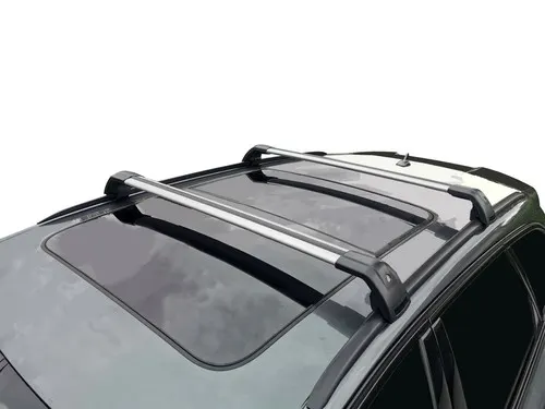
In addition to its functional purposes, the roof of a car also contributes to the car's overall appearance. Car manufacturers often use the roofline to create a distinctive look for their cars, whether it's a sporty coupe with a sleek roofline or a rugged SUV with a boxy, utilitarian design.
Manufacturing Technology:
- Hard top
- Sun roof
- T-top
- Targa top
- Vinyl’s top
Given Data:
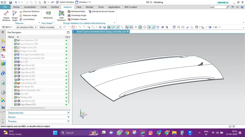
Given styling surface or class A surface
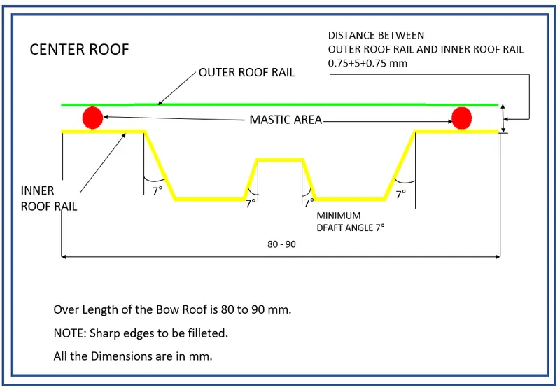
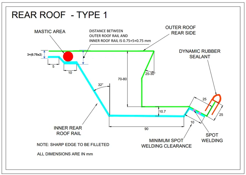
Master section's:
Procedure:
Roof Outer Panel
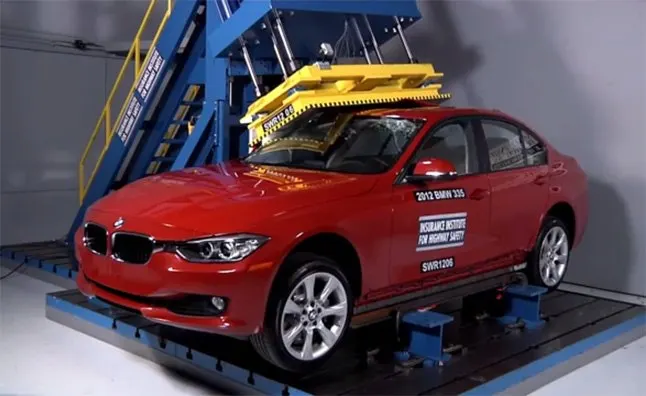
Roof Crush Test-
- A quasi-static test equipment made by MGA Research Corporation is used to evaluate roof strength.
- The system comprises of an upright assembly with a loading head connected that can be fixed at different heights from the ground as well as at pitch angles ranging from 5 to +5 degrees to accommodate testing on the driver or passenger side.
- The roll angle is set at 25 degrees all the time. The platen travels along two linear guides under the control of four hydraulic actuators. The complete system is fixed to a T-slot bed plate that is fastened to the test facility's floor.
Roof-
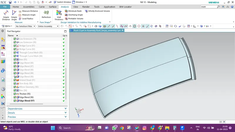
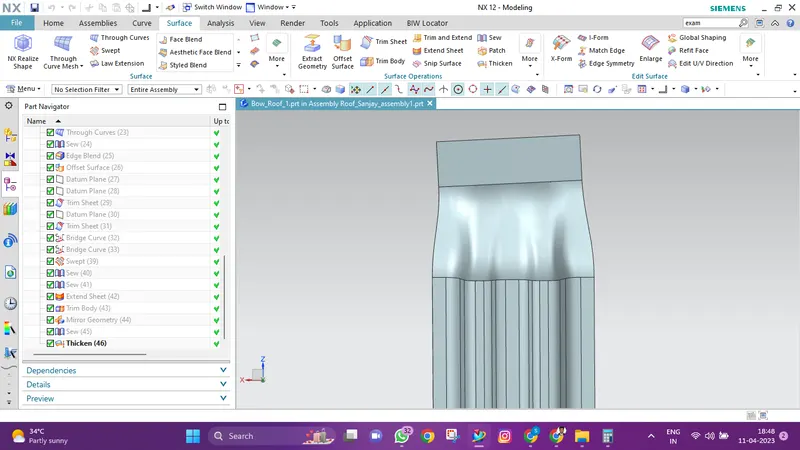
- The flanges or ditch areas at the four corners with the necessary open angle of 3 degrees were initially formed by first taking the input styling surface of the roof panel.
- We have provided a flange length of 21.5 mm at the front end of the roof panel to allow for appropriate clearance for the windscreen and any accompanying parts, such as rubber sealant.
- In order to facilitate the connecting for the backdoor, the rear end additionally produced flanges with the necessary length and opening angle.
- To strengthen the panel, more beads were added to the top of the roof panel.
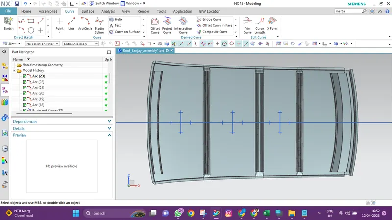
See the roof panel image below, which was created using styling information:
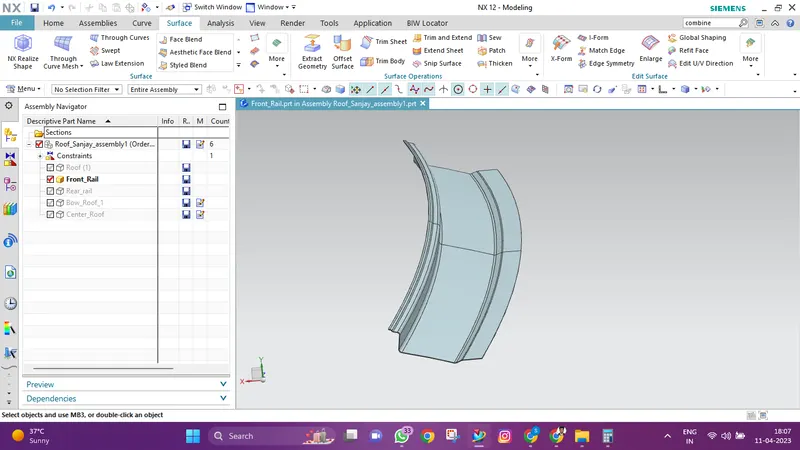
Front Roof Rail:
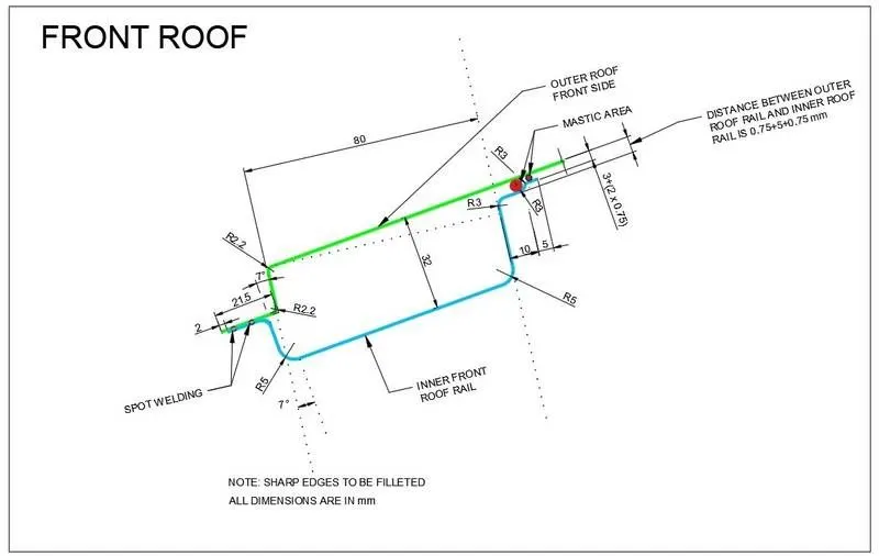
- The front roof rail serves as a support for the mounting brackets for the room lamp and the map lamp as well as strengthening the roof outer panel.
- It also connects the roof panel to the body side panel and windscreen glass.
- Based on the master section, which was designed with the functional specifications of the tool opening angle, needed clearance for connecting with the windscreen glass, vision requirements, depth based on head room clearances and clearance mastic joining, the front roof rail was created.
See the front roof rail design based on the master section, which is the master section utilised for the front roof rail, below:
Rear Roof Rail:
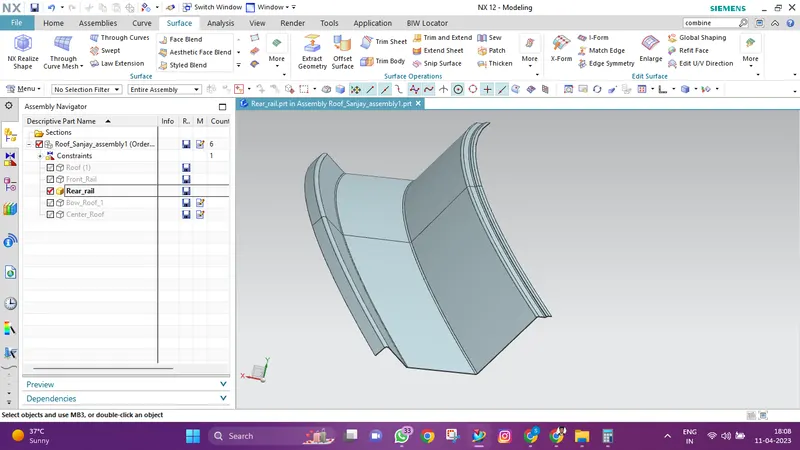
- The rear roof rail is typically made of high-strength steel or aluminum, and is designed to withstand the forces that are exerted on it during normal driving conditions, as well as in the event of a collision or rollover.
- It is also usually attached to the car's body using a series of bolts or other fasteners, which help to ensure that it remains securely in place.
- Rear Roof Rail connects the backdoor and the body side exterior and serves as an additional form of support for the outer panel.
- We have created a master section for creating the rear roof rail based on the functional needs of the rear visibility criteria, the rear head space clearance, the tool opening, and the mastic clearance.
View the rear roof rail design in the image below:
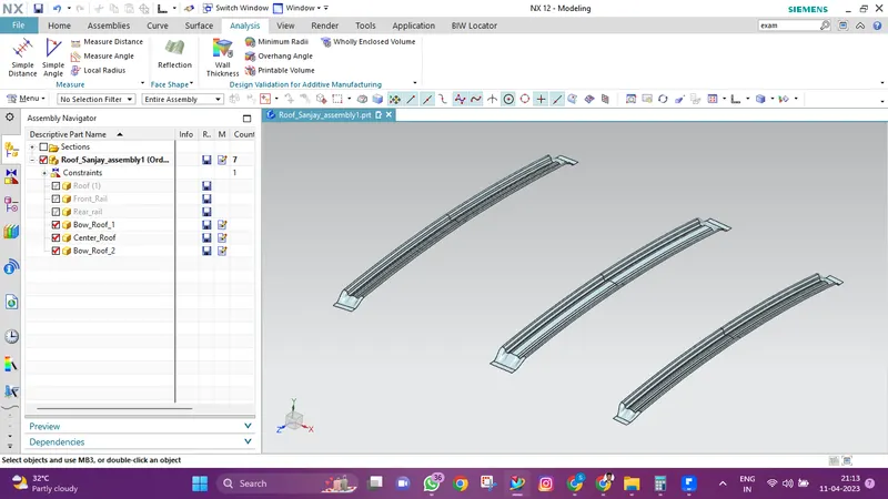
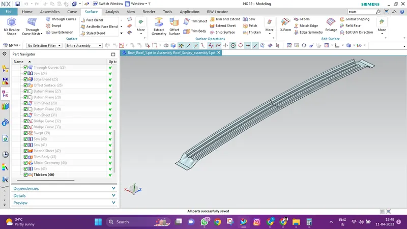
Bow Roof (Front, Center, Rear):
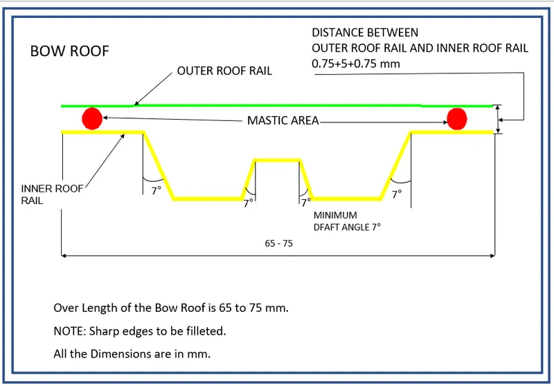
- Bow Roof Rails are another type of outer panel reinforcement that is used to strengthen the roof panel.
- They attach to the roof panel using mastic sealant and join to the body side using spot welding.
- These are created based on the master portions that were developed utilising the headroom clearance and visibility criteria.
- And it is typically advised to arrange these Bow roofs at the flat areas of the Roof outer panel.
- Another important design consideration is the choice of materials.
- The bows themselves are typically made from high-strength materials such as steel or aluminum, while the covering material is often a durable fabric or vinyl that is resistant to water, sun, and other environmental factors.
CALCULATION
Heat Distortion Criteria:
The use of sheet metal is heavily influenced by the heat distortion study. The temperature above which a material cannot be used for structural applications is known as the heat distortion temperature. With the aid of this investigation, it is possible to determine the heat distortion temperature—the point at which a material begins to soften when subjected to a fixed load at a high temperature. Based on the heat distortion temperature, this study will forecast the bow roof position, which helps to strengthen the roof, in order to prevent bending or damages.
Bow – roof prediction Formula
W = [1.73 x 10^(-3) x L] + [1.85 x 10^(-8) x (R^2)/t] + [ 1.10x10^(-3) x l] - 2.68
Where,
L = Roof Length in X-Direction[mm](Roof dimension in 0-Y)
R = Roof curvature
R = 2(Rx*Ry)/(Rx+Ry)
Rx = X curvature
Ry = Y curvature
t = Roof plate thickness [mm]
l = Bow Roof Span [mm]
Judgement Condition : OK< 2.7
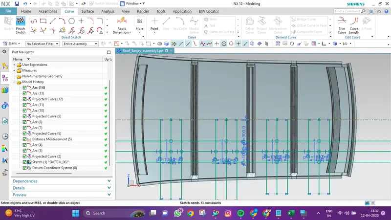
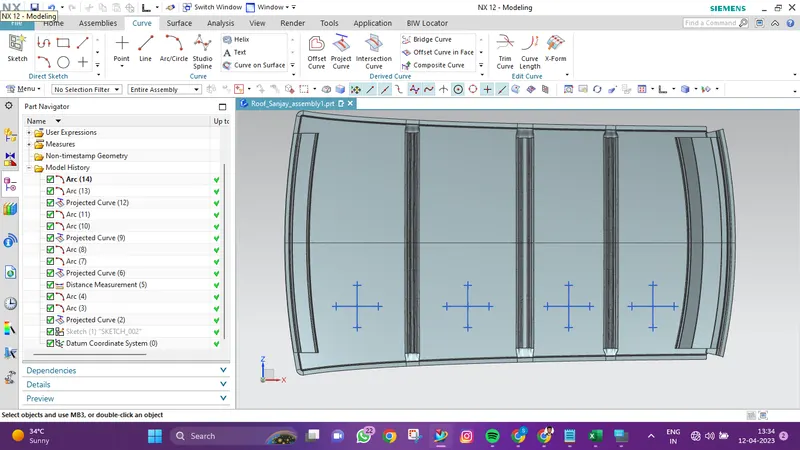
While applying the corresponding values in the formula we get the heat distortion as given below,

The preceding table shows that all values of w are below 2.7 and do not exceed 3.1, indicating that the bow row is currently positioned as intended and is functioning properly.
Snow Load Prediction Formula:
This test is carried out to determine how the roof will function with snow on it. Usually, the dent will occur as a result of the weight of the snow. However, the roof must be made so that it returns to its original position when the snow is removed. These are the prerequisites for the snow load criteria.
Qr = [Iy x t2] / [α x s x [(Rx + Ry)/2]2 x 10-8]
Note: The Qr value given over here is correct. There was a typo error in the formula given in the video.
Where,
α = My x Lx2 x 10-12 , My = Y(Ly-Y)
t = Roof plate thickness [mm]
Ly = Distance between the front and rear roof Rails on the Vehicle along with 0Y[mm]
Length of Roof panel with the center point between Roof rail Front /Rear as the front and rear reference point.
Lx = Distance between the Left and Right end of the roof on the Roof BOW [mm]
The width of the roof panel is exposed on the surface.
Y = Distance front Front Roof Rail to Roof BOW[mm]
s = Distance for which Roof BOW bears divided load [mm]
s = L1/2 + L2/2
Iy = Geometrical moment of inertia of Roof BOW (Y cross-section )[mm4]
Rx = Lateral direction curvature radius of roof panel Y cross-section on Roof BOW [mm]
Roof panel curvature Radius of the Length Lx in Front view
Ry = Longitudinal Direction curvature radius of the Roof panel X cross-section on Roof BOW [mm]
Roof panel X curvature radius of length s in Side view
Judgment condition
Qr ≥ 3.1
250 ≤ s ≤ 380
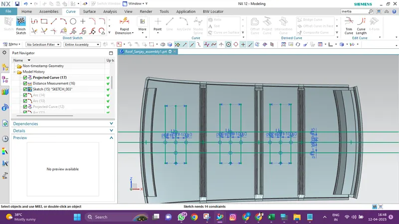
While applying the corresponding values in the formula we get the Snow load prediction as given below,

It is evident from the values that values of QR > 3.1 were attained.
Moment Of Inertia
Bow Roof Front:
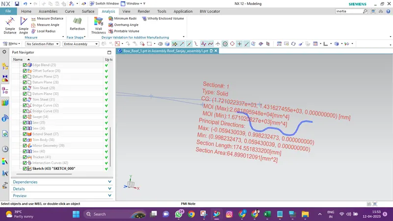
Moment of inertia maximum,( MAX) I max =2.6818*10^4( mm4)
Moment of inertia maximum ,( MIN) I min =1.671*10^3( mm4)
Bow Roof Rear:
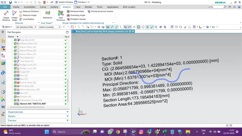
Moment of inertia maximum,( MAX) I max =2.666*10^4( mm4)
Moment of inertia maximum ,( MIN) I min =1.6378*10^3( mm4)
Center Reinforcement Rail:
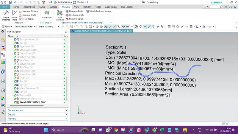
Moment of inertia maximum,( MAX) I max =4.797*10^4( mm4)
Moment of inertia maximum ,( MIN) I min = 1.5930*10^3( mm4)
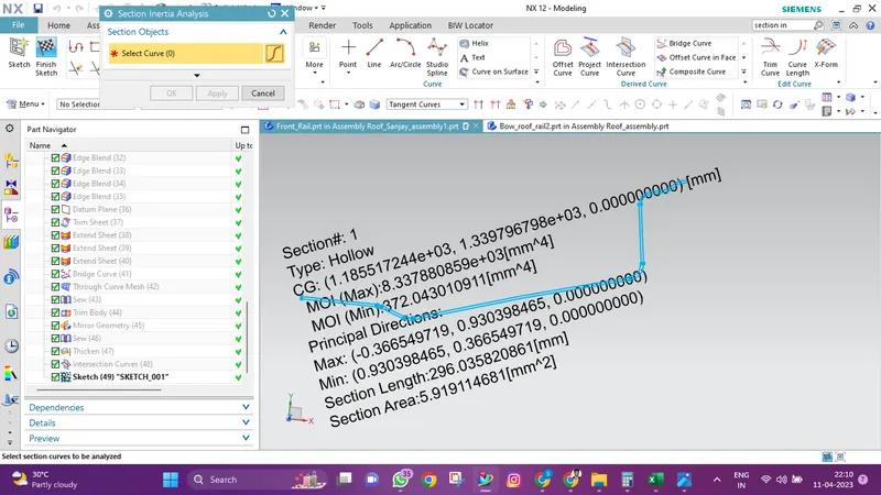
Front Roof Rail:
Rear Roof Rail:
Moment of inertia maximum,( MAX) I max =8.337× 10^3 ( mm4)
Moment of inertia maximum ,( MIN) I min =372.043010( mm4)
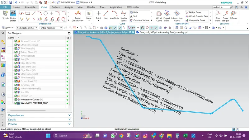
Moment of inertia maximum,( MAX) I max =9.355× 10^3 ( mm4)
Moment of inertia maximum ,( MIN) I min =7.240× 10^3 ( mm4)
Draft Analysis
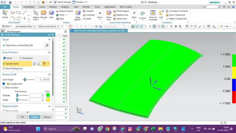
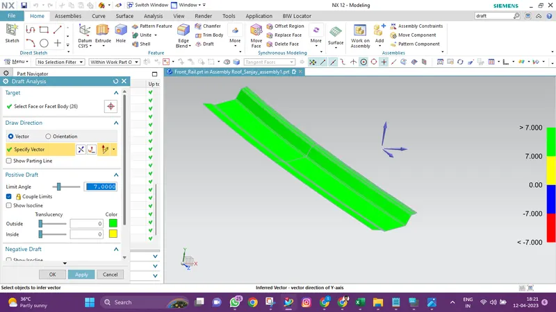
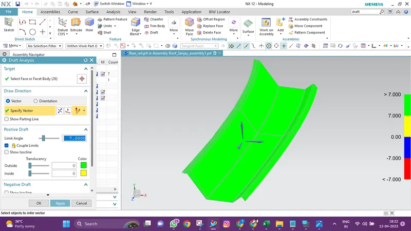
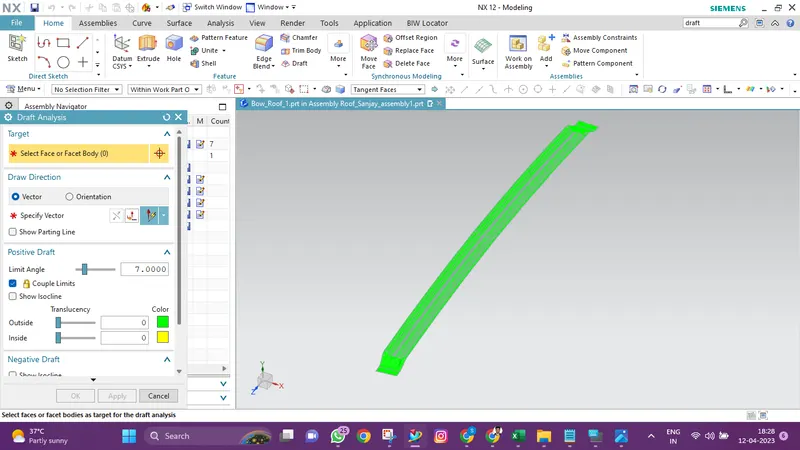
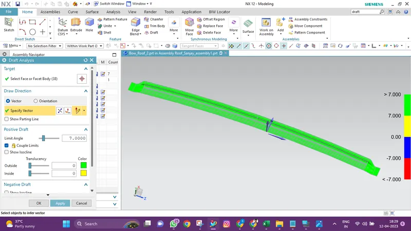
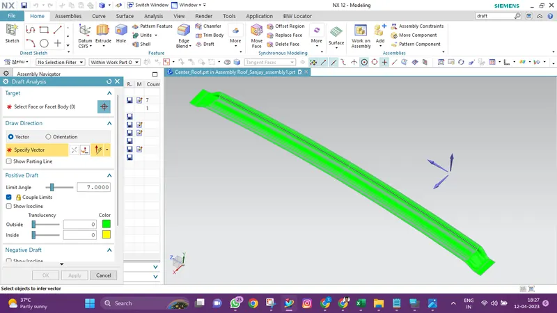
- You can determine whether the part you drafted will be simple to remove using the Draft Analysis tool.
- In this kind of analysis, zones on the analysed element are identified by colour ranges where the deviation from the draught direction at any given position corresponds to predetermined values.
- For analysis, a minimum draught angle of 7 degrees is taken into account.
- Green indicates a component with a positive draught angle greater than 7 degrees.
Roof Outer Panel:
Front Roof Rail:
Rear Roof Rail:
Front Bow Roof:
Rear Bow Roof:
Center Bow Roof:
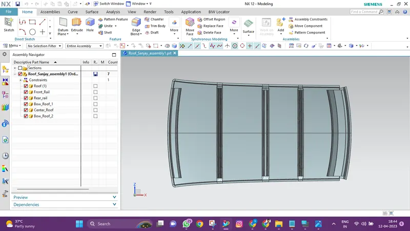
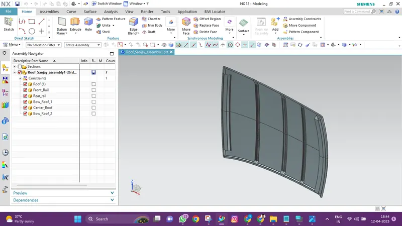
Final Design
CONCLUSION
Thus, the roof, front roof rail, bow roof rails, central roof rail, and rear roof rail are designed in accordance with the master sections, and moment of inertia and draught analysis are performed to determine whether manufacturing is feasible.