Week 11 - Final project
AIM
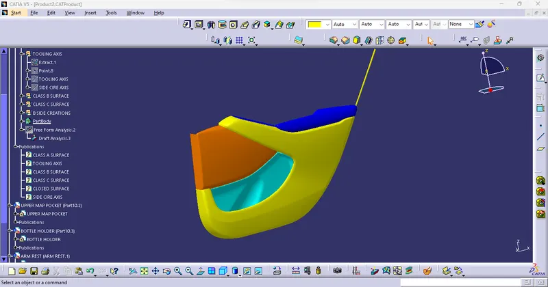
To develop of a Door Trim panel considering following inputs as like in OEM and tier1 companies.
- a) Class A surface
- b) Nominal thickness : Refer master sections
- c) Attachment strategy
Software Used For The Creation Of Model
- CATIA V5
INTRODUCTION
- Door Trim Panel:
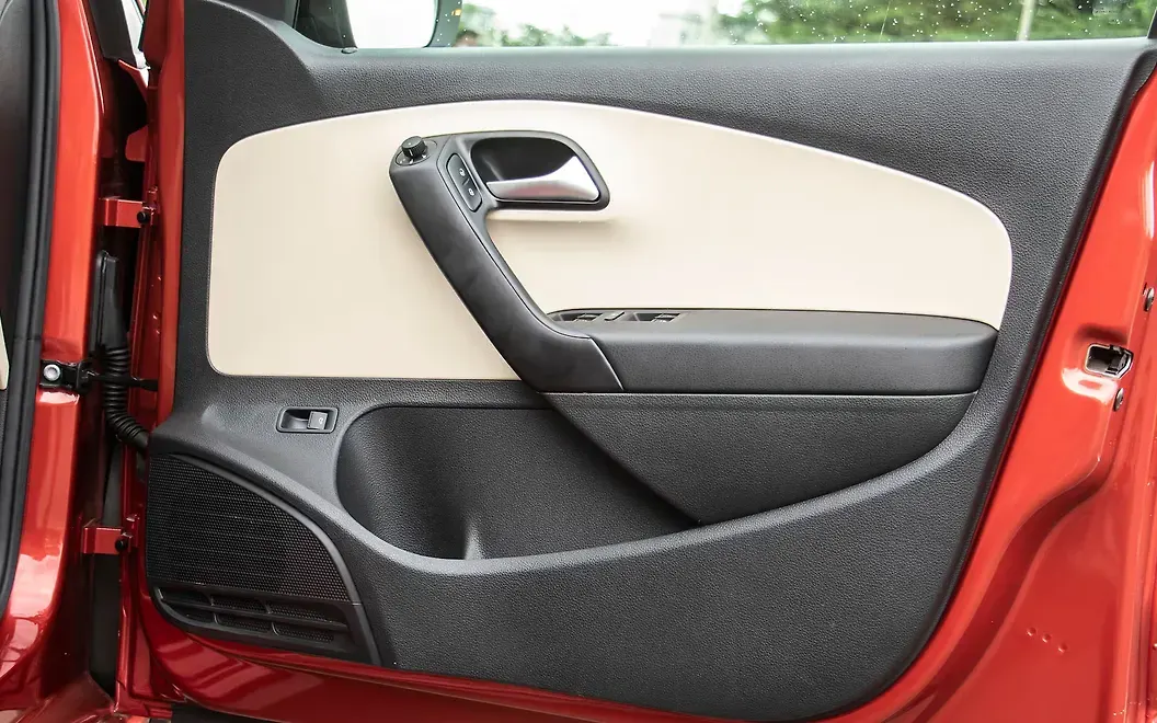
The door's inner mechanisms and the vehicle's interior are connected by the door panel, as are the passengers within the automobile and the door. They must adhere to a number of design requirements in terms of operation, appearance, and safety. They should also maintain the dashboard's material motif while hiding complex electrical and mechanical parts that control the vehicle's locks, windows, and other amenities. From a straightforward latch and winding mechanism in two parts, the door panel has developed into a more complex enclosure. Nowadays, doors have an interior full-width panel with speakers, electronic glass, and a central locking system. These panels typically have a foamed core that is wrapped in either plastic or fabrics.
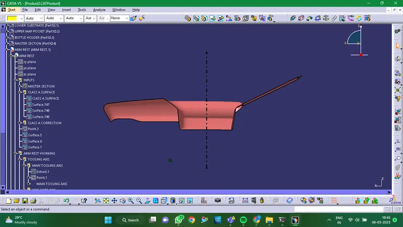
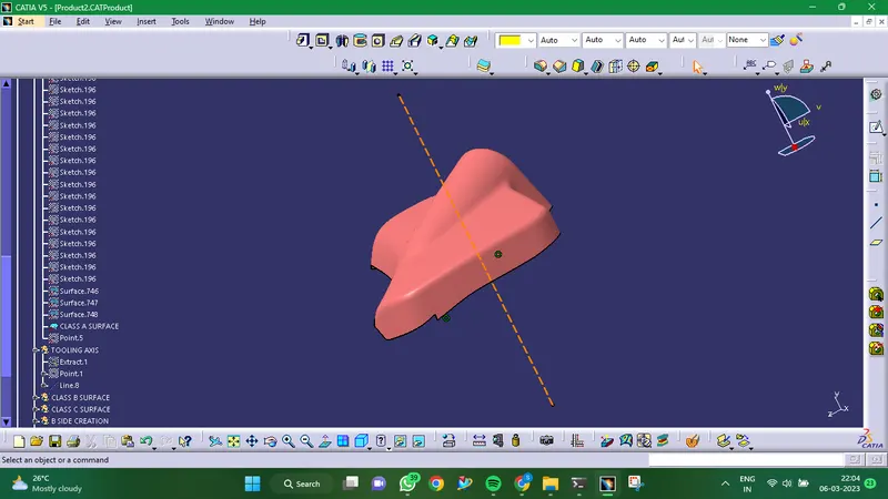
- Tooling Axis:
The tooling axis is the direction in which the mould, core, or cavity opens. Connectivity of Class-A Surface: STEP 01 Creating boundaries or just utilising the join option will allow you to check the surface's connectedness while making any openings visible.
- Draft Analysis:
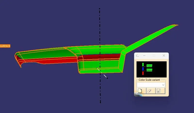
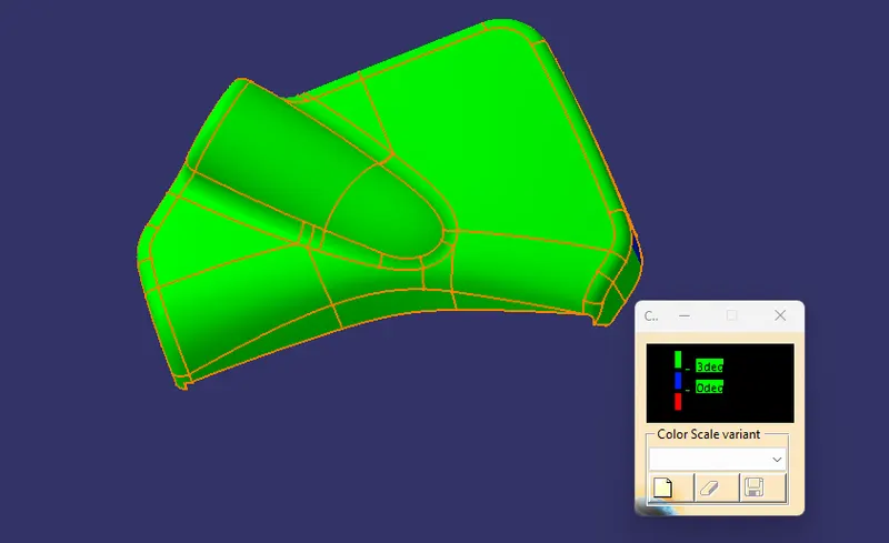
On the components where materials are ejected after being created inside of tools, draught analysis is carried out. In the production of automotive sheet metal, the blank sheet is transformed into vehicle panels such as the hood, fender, roof, side doors, and back doors, among others.
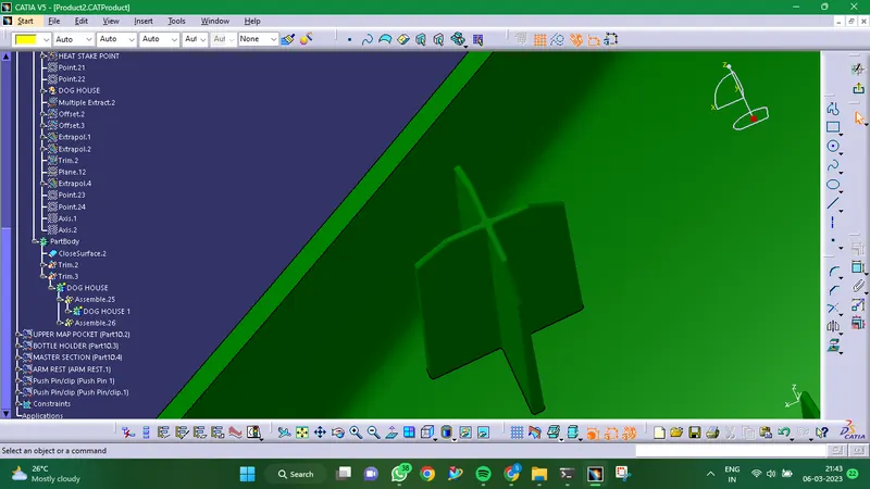
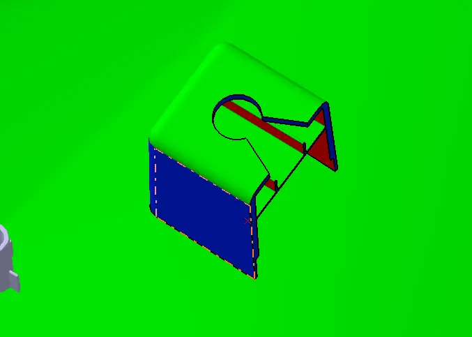
- Dog House:
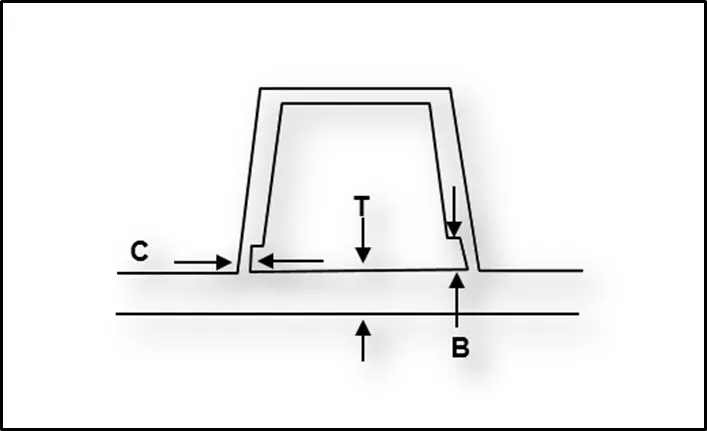
- Doghouse wall thickness should be 40% or less than the main wall stock where it intersects with portion wall (C) ( T ).
- (B)'s height should range from 3.0 to 6.0 mm.
- Doghouses must have a minimum Doghouse Width (X) of 12 mm.
- A doghouse requires a minimum Draft (D) of 1.5 degrees* to die draw.
DESIGN PROCEDURE
Components:
- ARM REST
- LOWER SUBSTRATE
- UPPER MAP POCKET
- BOTTLE HOLDER
- ARM REST
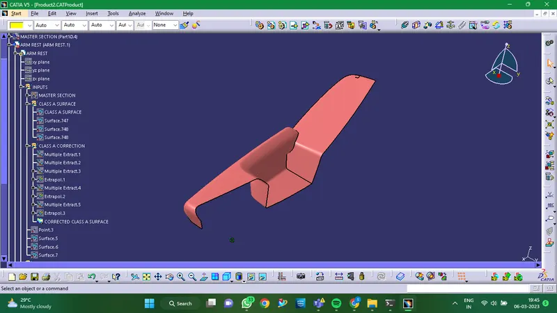
- Given Class A Surface:
- Making Of Tooling Axis:
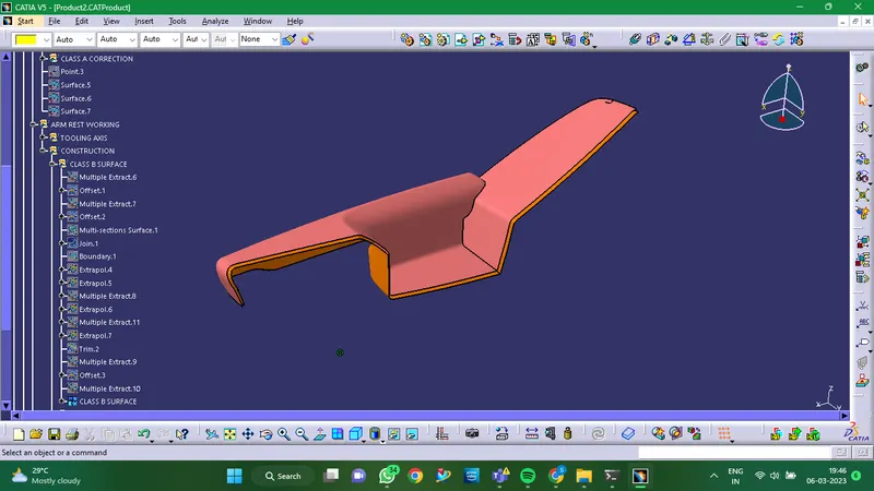
- Creation Of Class B Surface:
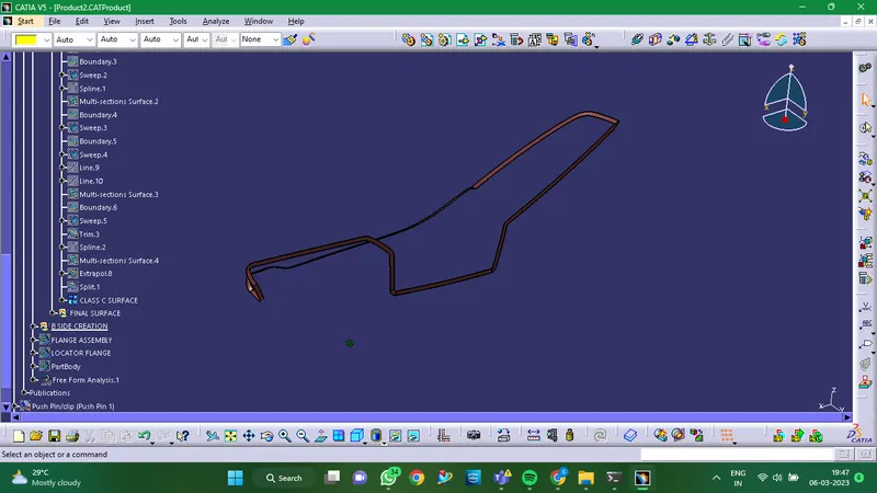
- Creation Of Class C Surface:
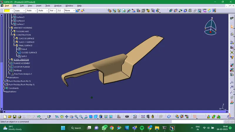
- Final Closed Surface:
Closed surface is formed by joining of Class A, Class B and Class C Surfaces together.
- Flange Creation:
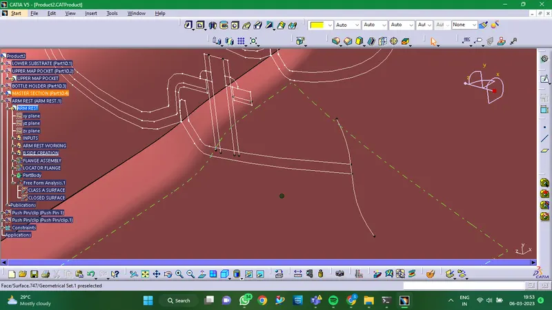
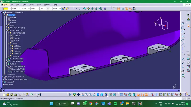
Flange Thickness of 2.5mm
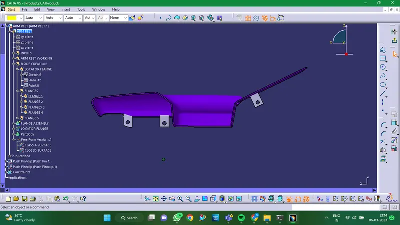
- Draft Analysis:
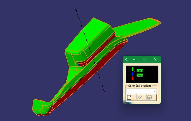
- LOWER SUBSTRATE
- Given Class A Surface:
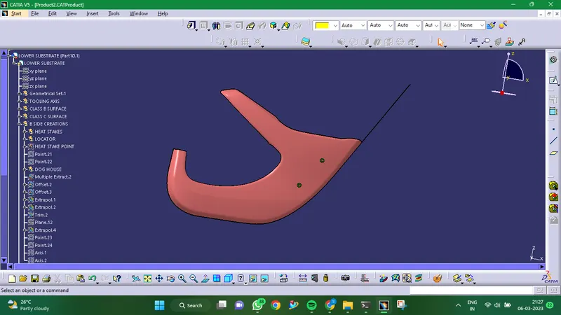
- Creation Of Tooling Axis:
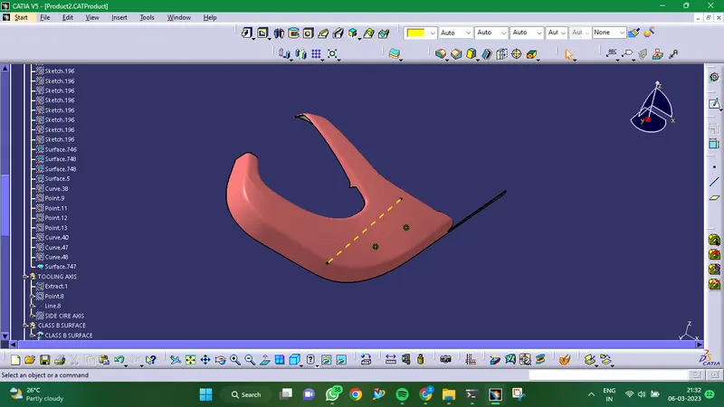
- Creation Of Class B Surface:
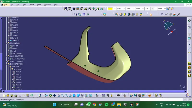
- Creation Of Class C Surface:
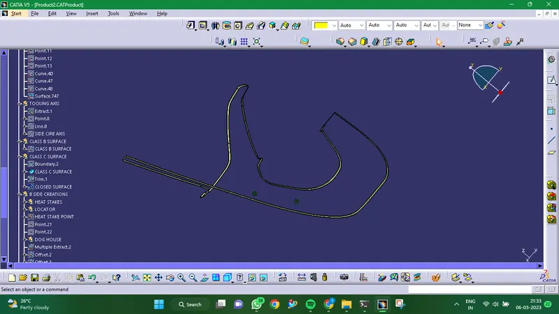
- Final Closed Surface:
Closed surface is formed by joining of Class A, Class B and Class C Surfaces together.
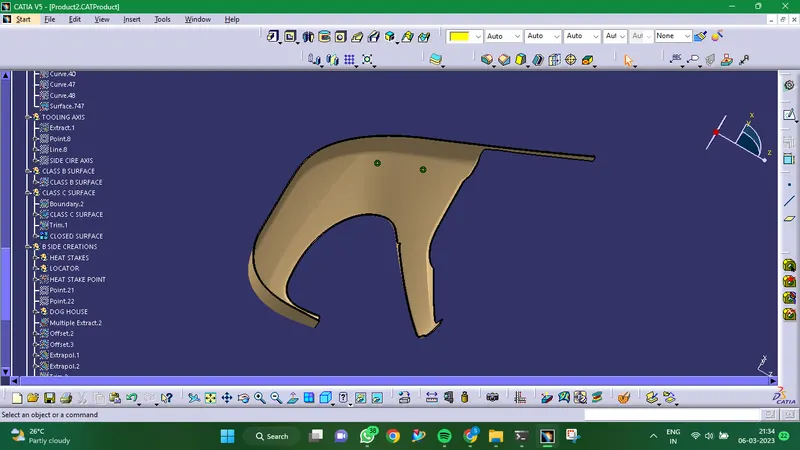
- Creation Of Dog House:
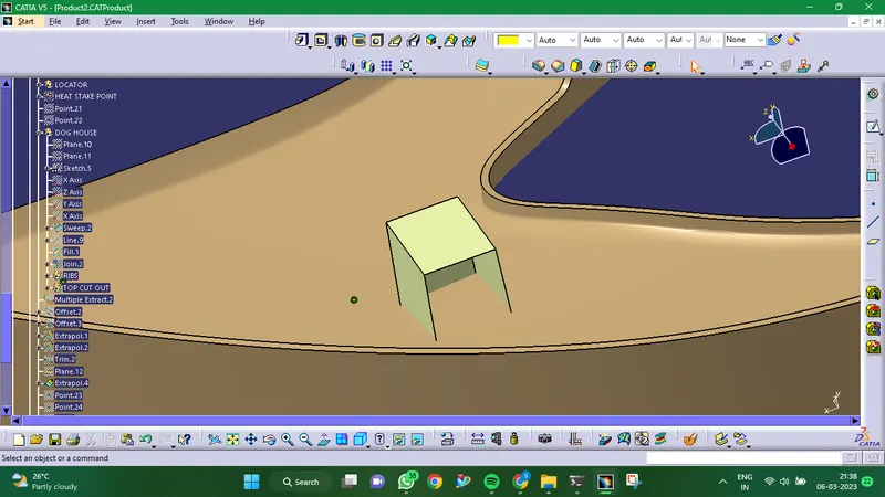
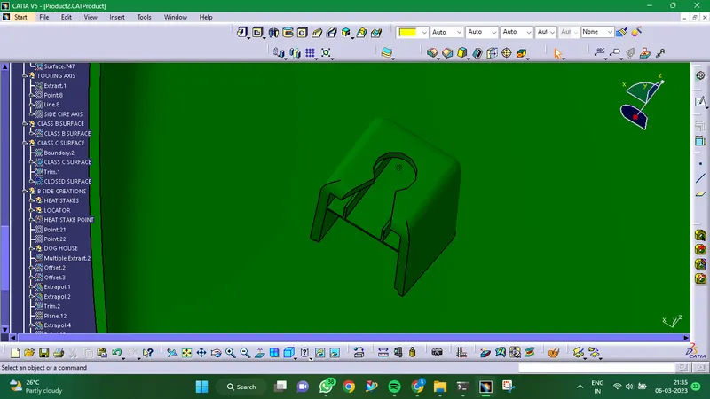
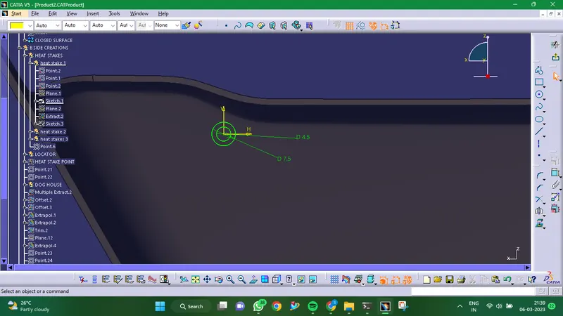
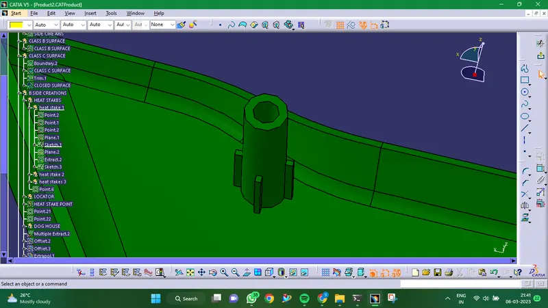
- Creation Of Heat Stakes:
By carefully melting and reconstructing a plastic stud or boss, thermal staking is an assembly technique that holds or locks another plastic or metal component of an assembly in place.
Heat stakes creation guidelines:
- Minimum 15 mm should separate each heat stake.
- The counter should have a maximum clearence of 0.5 mm.
- Fillet radius should not exceed 0.25 mm.
- 0.5 degree per side in the draught.
- Creation Of Locators:
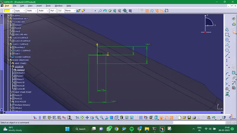
Locators are used to place the parts exactly where they need to be and serve as a guide for putting the two parts together.
Instructions for Writing Locators:
- 0.5 degree per side in the draught.
- Typically 40% wall thickness for thickness.
- 0.25mm is the maximum fillet radius.
- Final Component:
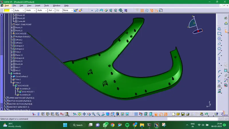
- Draft Analysis:
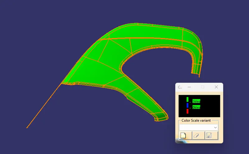
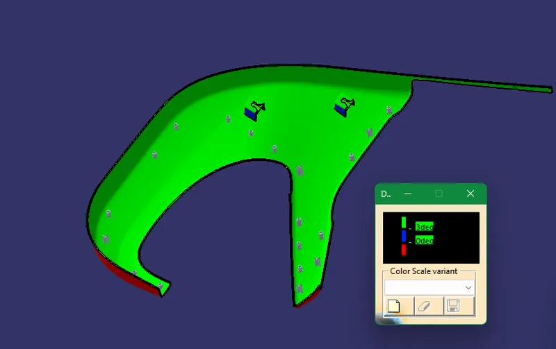
- UPPER MAP POCKET
- Given Class A Surface:
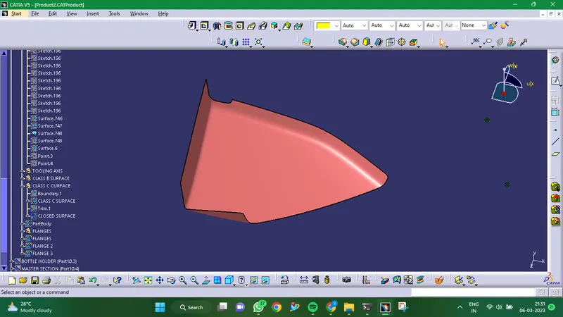
- Creation Of Tooling Axis:
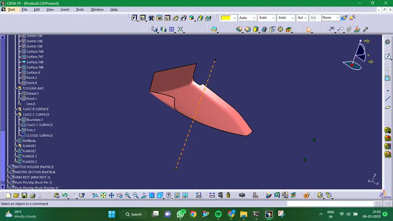
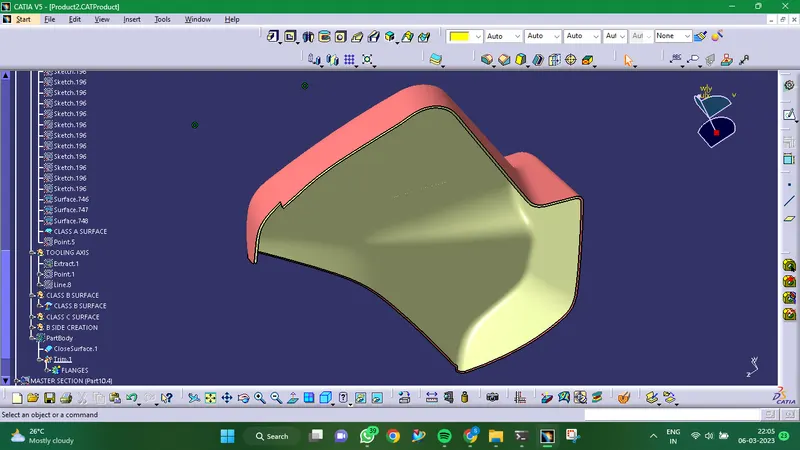
- Creation Of Class B Surface:
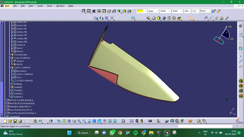
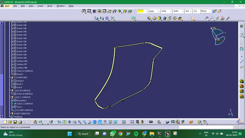
- Creation Of Class C Surface:
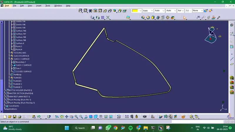
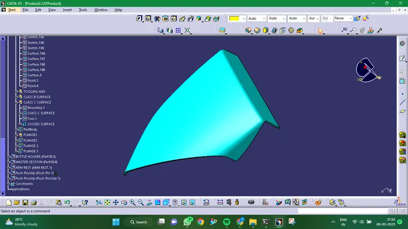
- Final Component:
Closed surface is formed by joining of Class A, Class B and Class C Surfaces together.
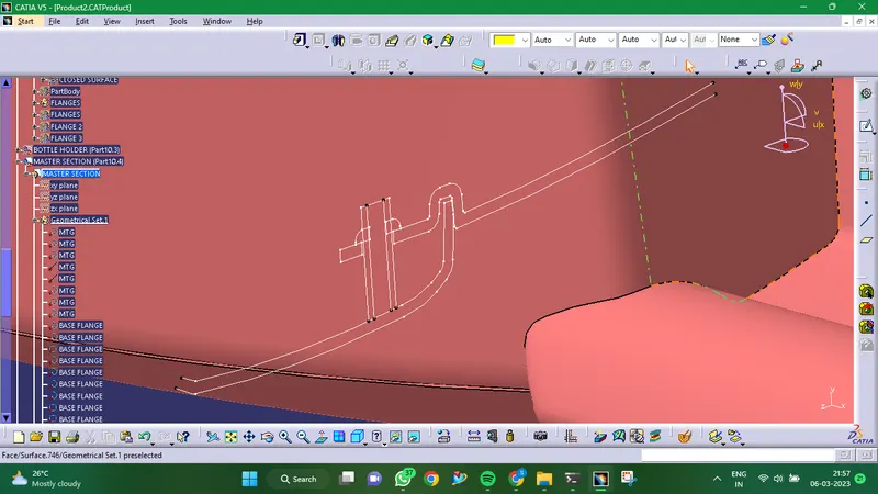
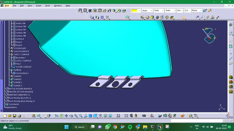
- Creation Of Flanges:
- BOTTLE HOLDER
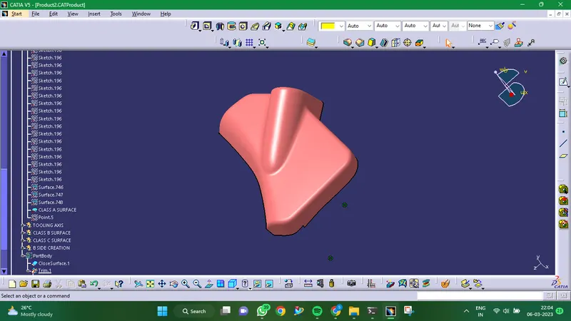
- Given Class A Surface:
- Creation Of Tooling Axis:
- Creation Of Class B Surface:
- Creation Of Class C Surface:
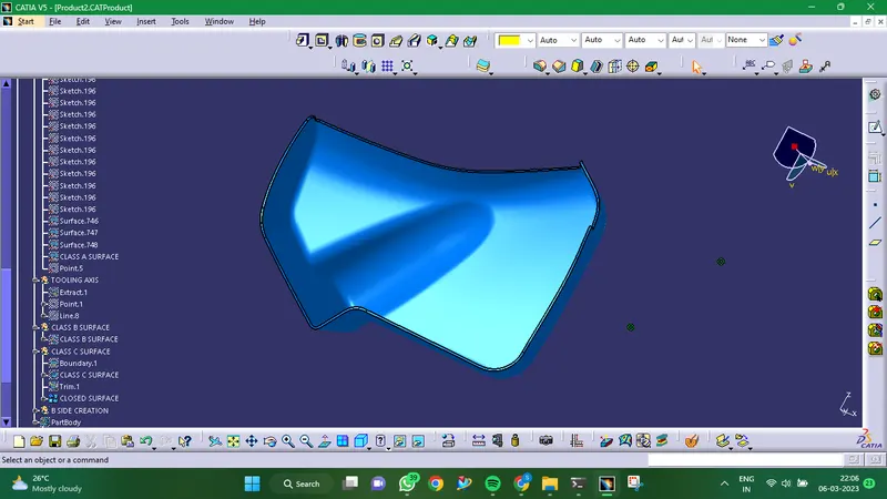
- Final Component:
Closed surface is formed by joining of Class A, Class B and Class C Surfaces together.
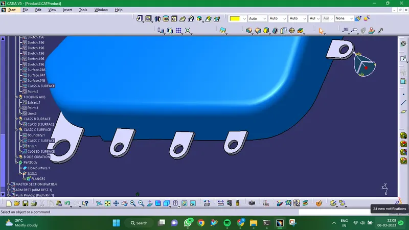
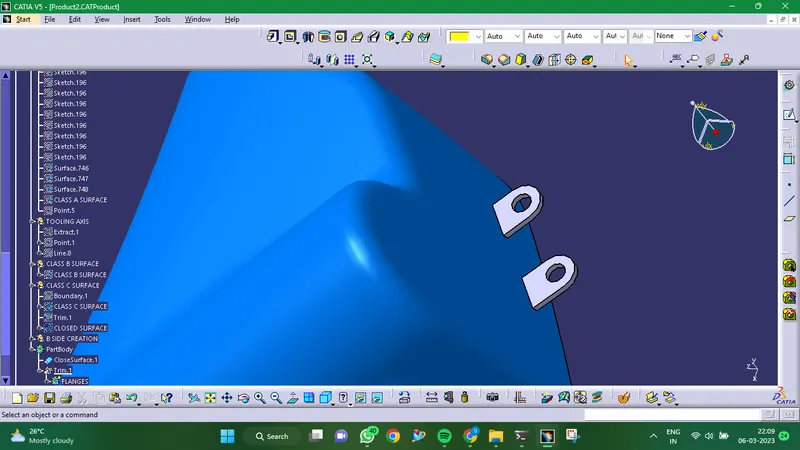
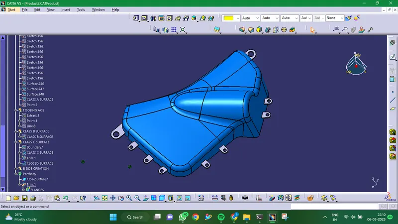
- Creation Of Flanges:
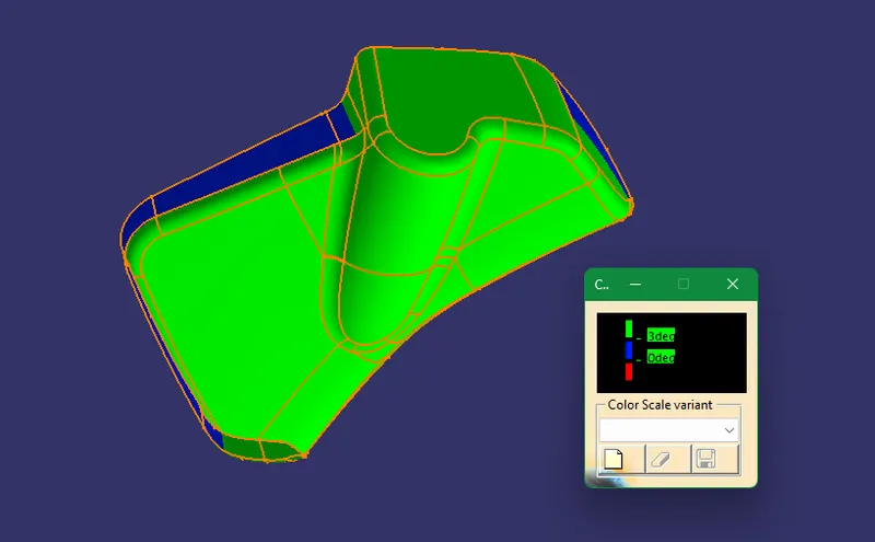
- Draft Analysis:
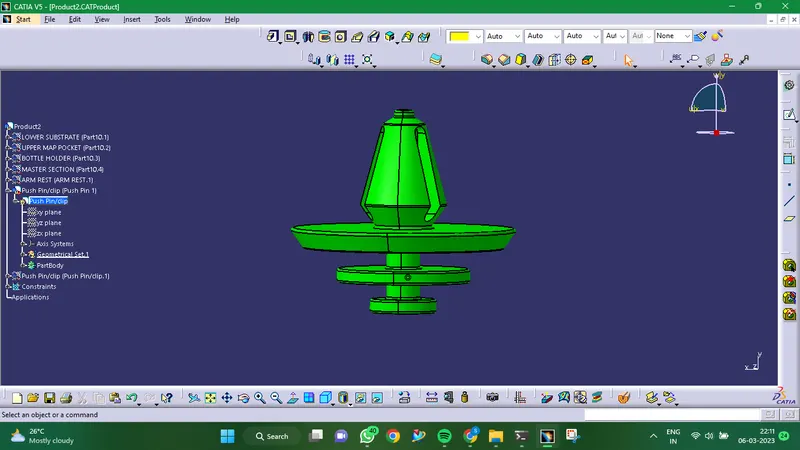
- PUSH PIN
Push pins that aid in component location and arrestment, alignment of mating parts, and function as various mechanism guides. They essentially have a connection to the dog house.
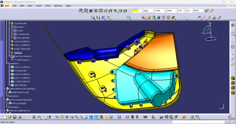
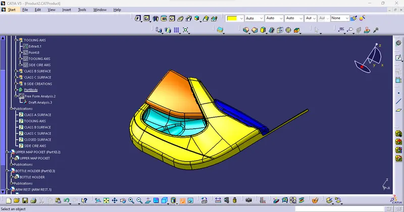
- FINAL ASSEMBLY:
CONCLUSION
In light of these design guidelines, the Door Trim panel CAD model is developed by tier 1 and OEM firms.