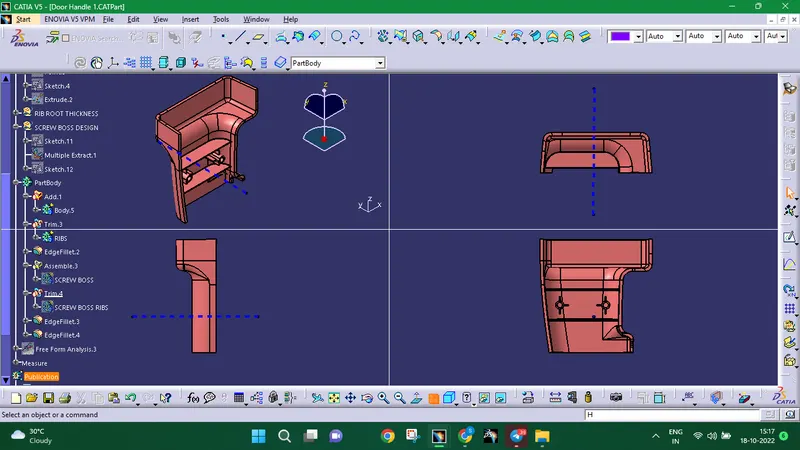
Week 9 - Attachment Feature Creation (Ribs & Screw Boss) - Challenge 1
AIM
- To Create the Door Handle Component from the given Class-A surface
- To Create the rib for the Drill Handle.
- To Create the screw boss for the Drill Handle.
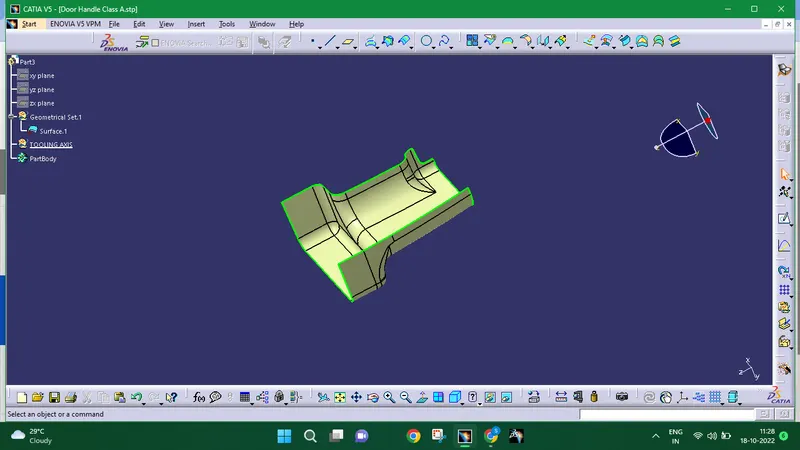
GIVEN CLASS A SURFACE:
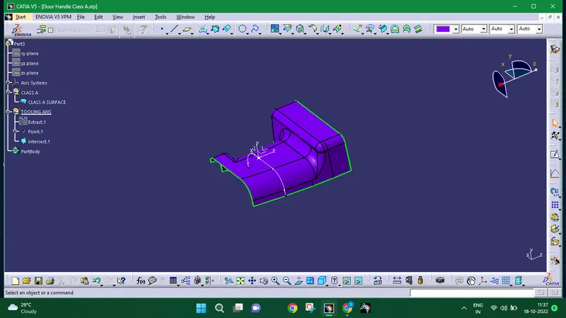
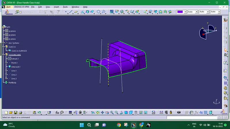
CREATION OF TOOLING AXIS:
- The direction in which a part is pulled out of a mould is known as the tooling direction.
- Basically, the mould is constructed out of two independent components. You have the Core side and the Cavity side.
- The Dye line or Tooling Direction is when the Core separates from the Cavity.
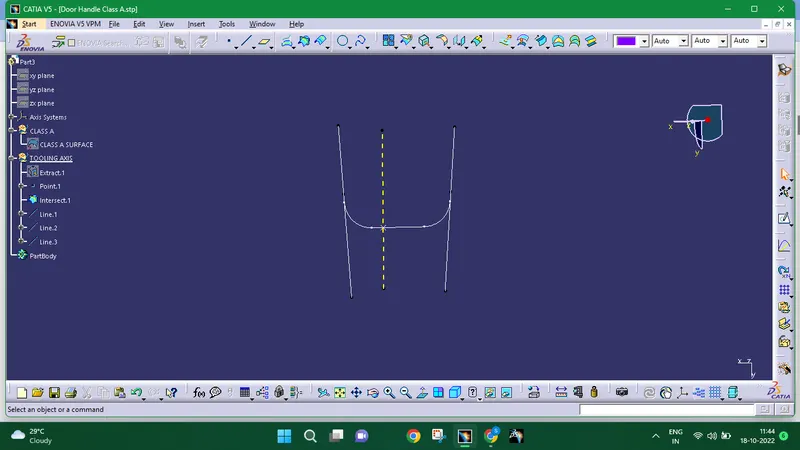
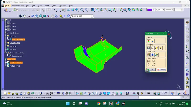
DRAFT ANALYSIS:
- We can determine whether the part you drafted will be simple to remove using the Draft Analysis tool. In this kind of analysis, zones on the investigated element are identified by colour ranges where the deviation from the draught direction at any given place corresponds to predetermined values.
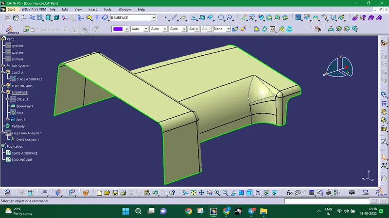
CREATION OF CLASS B SURFACE:
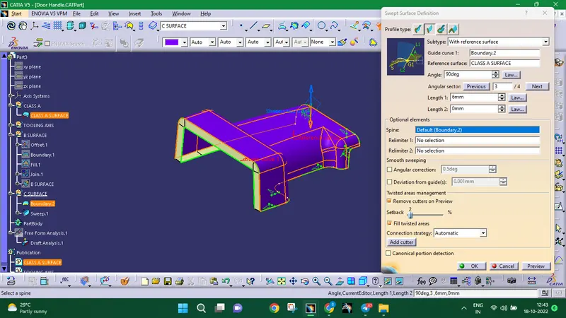
CREATION OF CLASS C SURFACE:
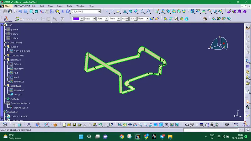
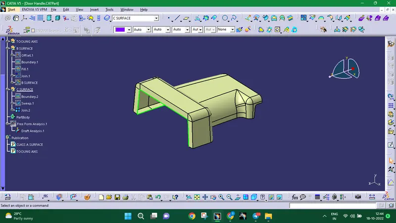
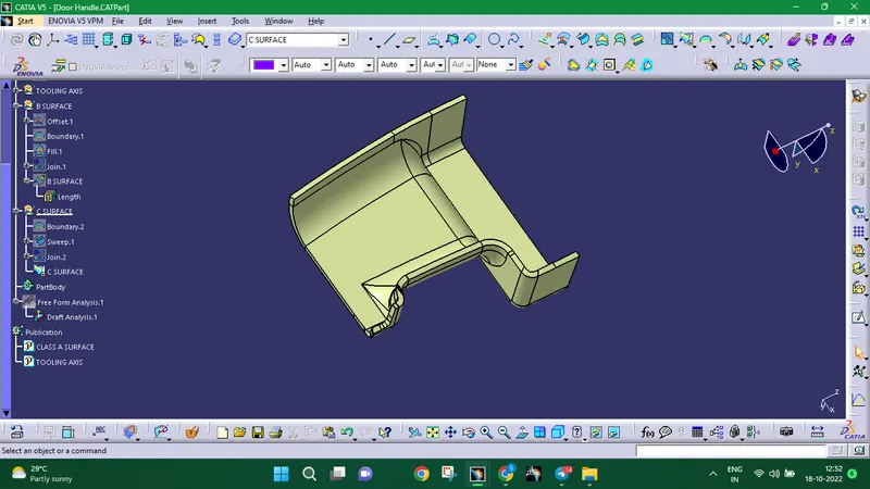
CLOSED SURFACE:
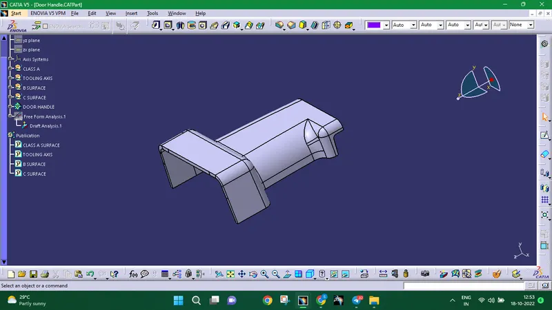
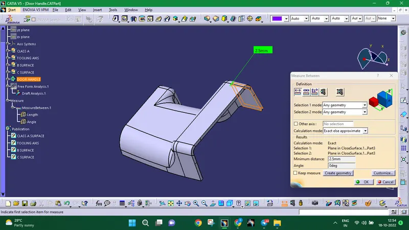
THICKNESS OF 2.5MM:
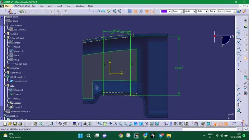
RIB CREATION
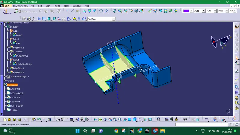
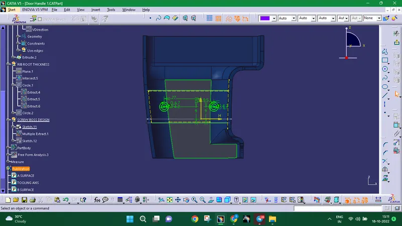
SCREW BOSS CREATION
- Draft - 0.5 degrees on the walls of boss
- Thickness - Typically 40%* of the nominal wall at the base.
- Height to Diameter Ratio - 3:1
- Radii - 0.25mm maximum radii.
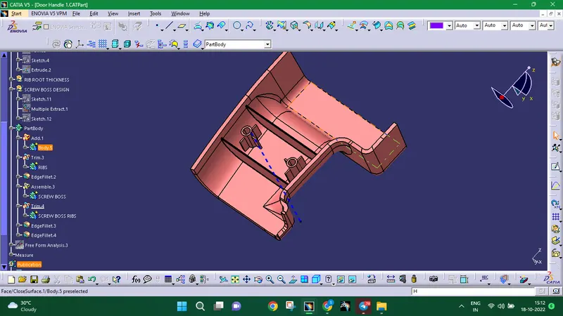
various orientations (Isometric, Front, Side, and Top View):