Wiring harness design in CATIA V5 - 3D modeling Week 2 Challenge
Wiring harness design in CATIA V5 – 3D modelling Week 2 Challenge
Aim:
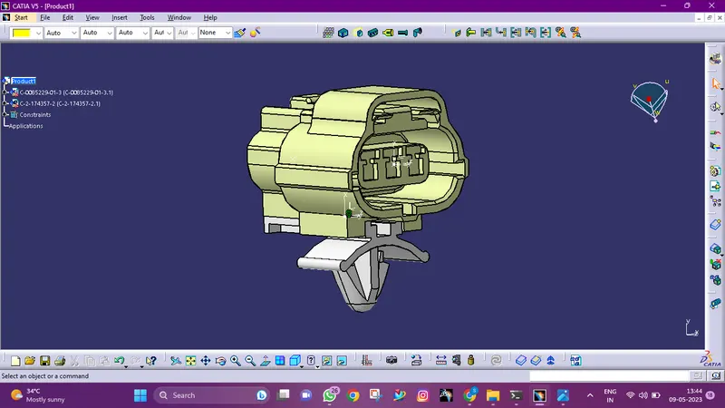
Download following connectors & Connector clip cad data from given link & define it as Electrical Connector using Electrical Part design Workbench. Define all the necessary properties to Connectors & Clip.
- Deutsch DT06 – 08SA ( https://www.te.com/usa-en/product-DT06-08SA.html)
- Tyco 174357-2 (https://www.te.com/usa-en/product-2-174357-2.html?source=header-match)
- Tyco 85229-1 – (https://www.te.com/usa-en/product-85229-1.html?q=85229&source=header)
INDRODUCTION
Wiring Harness:
A wiring harness, also known as a cable harness or wiring loom, is a collection of wires, connectors, and other electrical components assembled together to form a complete electrical system. It is typically used to transmit electrical signals and power between different components in a vehicle or machinery.
Wiring harnesses are designed to provide a reliable and secure connection between various electrical components, while minimizing the risk of electrical interference or signal loss. They can vary in size and complexity depending on the application, ranging from simple assemblies with only a few wires to complex harnesses with hundreds or even thousands of wires.
Wiring harnesses can be custom-designed for specific applications, or they can be pre-manufactured for use in a wide range of vehicles and machinery. They are typically made up of several individual wires that are bundled together, either by wrapping them in a protective sheath or by using clips or other fasteners to hold them in place.
Overall, wiring harnesses play a critical role in modern electrical systems, helping to ensure the safe and efficient operation of a wide range of equipment and devices.
Vehicle Electrical Distribution System(EDS):
A vehicle electrical distribution system is a complex network of wires, connectors, and electrical components that work together to provide power and control signals to various systems and components in a vehicle. The electrical distribution system is responsible for delivering power from the battery to various subsystems such as the engine, transmission, lights, entertainment system, and other electronic devices.
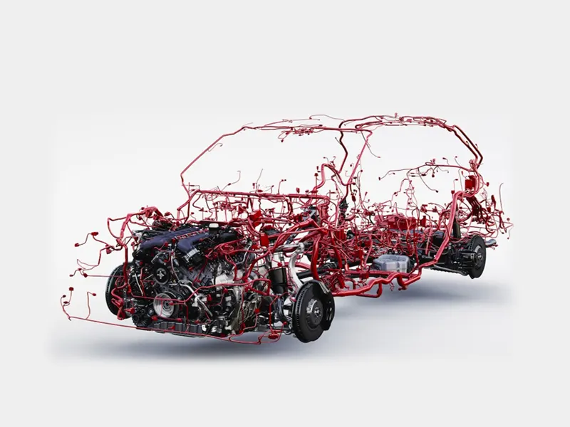
The key components of a vehicle electrical distribution system include the battery, alternator, starter motor, and various relays and fuses. The battery serves as the primary power source for the system, while the alternator is responsible for recharging the battery and providing power to the electrical system while the engine is running. The starter motor is responsible for starting the engine, while the relays and fuses help to protect the system from damage due to electrical faults and overload conditions.
Wiring Harness Design Process:
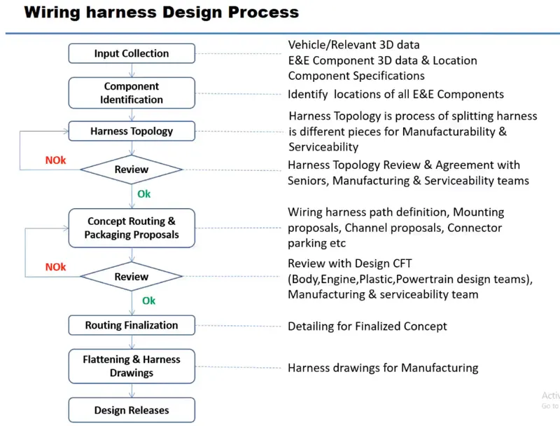
The process of designing a wiring harness typically involves several key steps:
-
Requirements gathering: The first step in designing a wiring harness is to gather requirements. This involves understanding the electrical components that need to be connected, the power and signal requirements of each component, and any specific environmental or regulatory requirements that must be met.
-
Circuit design: Once the requirements are understood, the next step is to design the electrical circuits that will be used in the wiring harness. This involves selecting the appropriate wire sizes, connectors, and other components, and designing the circuits to ensure proper power and signal distribution.
-
Routing and packaging: After the circuits have been designed, the next step is to determine how the wiring harness will be routed and packaged within the vehicle or machinery. This involves considering factors such as space constraints, accessibility, and protection from environmental factors such as heat, moisture, and vibration.
-
Prototype development: Once the design is complete, a prototype wiring harness can be developed for testing and validation. This typically involves building a physical prototype of the harness and testing it under various conditions to ensure proper function.
-
Production and quality control: Once the prototype has been validated, the wiring harness can be put into production. During production, quality control measures are implemented to ensure that each harness meets the specified requirements and is free from defects.
-
Installation and testing: Finally, the wiring harness is installed in the vehicle or machinery and tested to ensure that it functions properly and meets all regulatory and environmental requirements.
Overall, designing a wiring harness requires careful consideration of the electrical components involved, as well as the specific requirements and constraints of the application. By following a systematic design process, engineers can create wiring harnesses that are reliable, efficient, and cost-effective
PROCEDURE
- Deutsch DT06 – 08SA
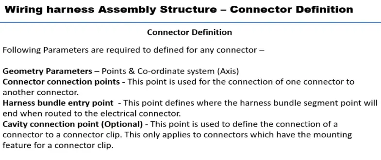
Creation of connector connection point:
Make a midpoint on the contact face for wire bunddle insertion.
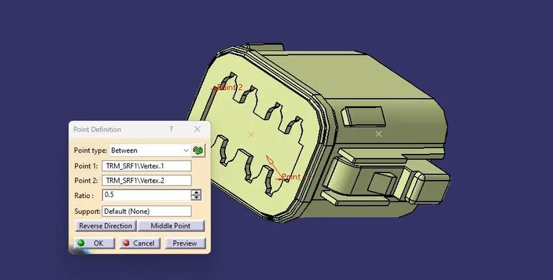
Create an axis system referencing the newly generated point and specifying the axis direction.
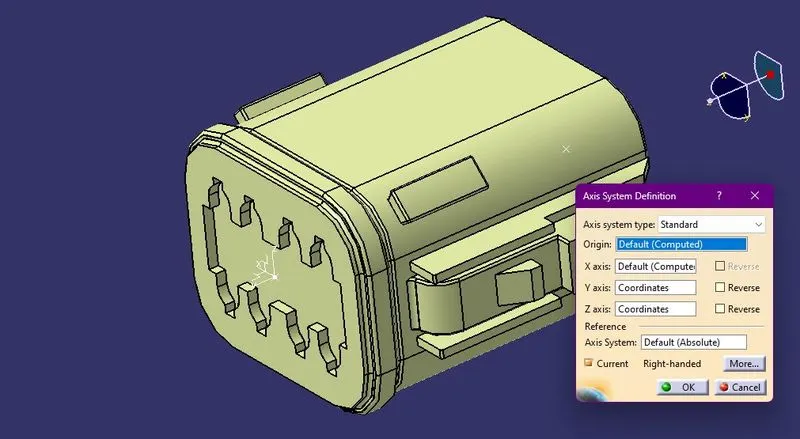
- The Y-Axis should be oriented towards the connector's front face.
- The X-Axis should be oriented towards the clip's locking mechanism.
- The Z-axis should be pointing across the connector from left to right.
Creation of Bundle Conncection Point:
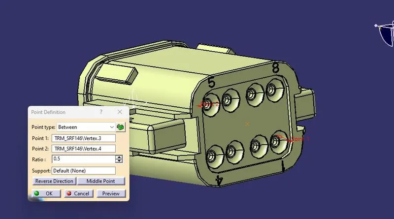
In CATIA Electrical Part Design,
Define the part as a connector and specify that there are 8 terminations because there are 8 wire entry points.
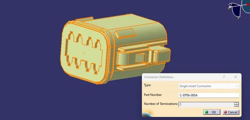
Define Bundle connection point:
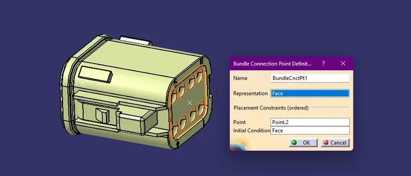
Define connector connection point:
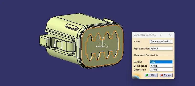
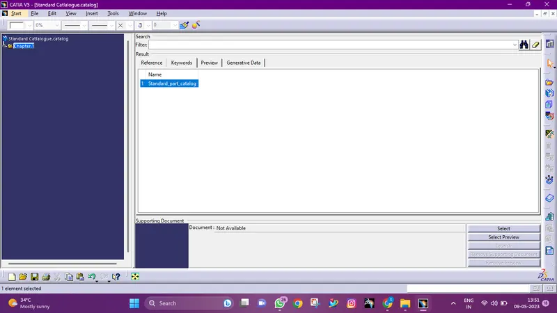
creating a catalogue:
- Tyco 174357-2
Creation of connector connection point:
Make a midpoint on the contact face for wire bunddle insertion.
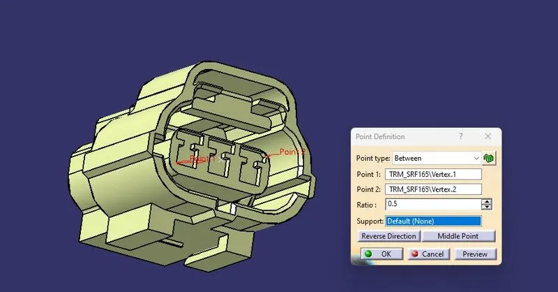
Create an axis system referencing the newly generated point and specifying the axis direction.
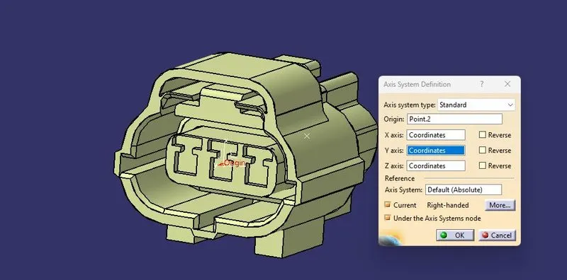
Create cavity connection point and create cavity connection axis system
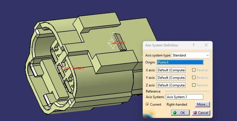
Creation of Bundle Conncection Point:
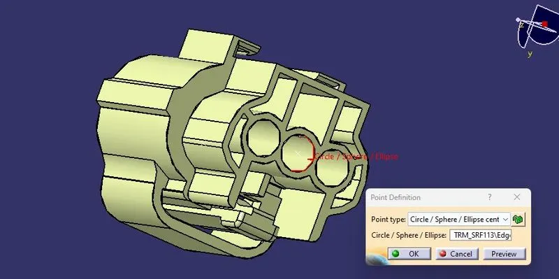
In CATIA Electrical Part Design,
Define the part as a connector and specify that there are 8 terminations because there are 3 wire entry points.
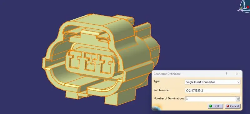
Define Bundle connection point:
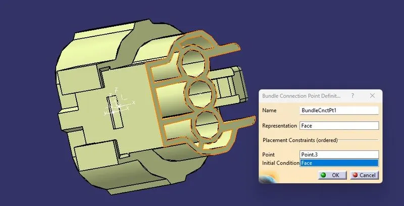
Define connector connection point:
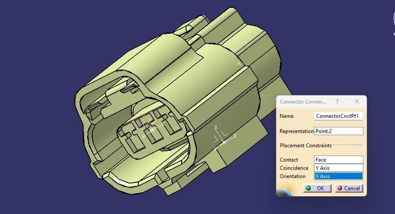
Define cavity connection point:
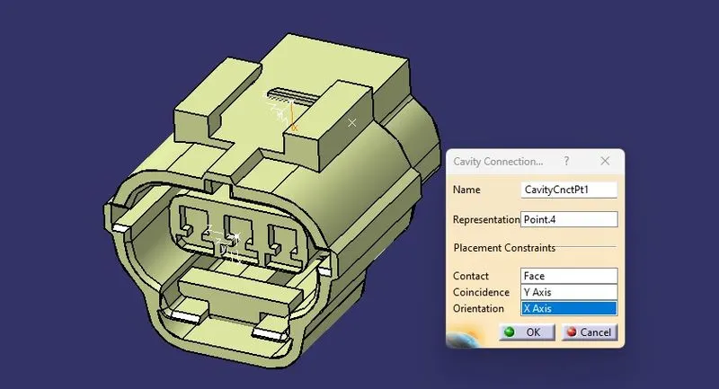
- Tyco 85229-1
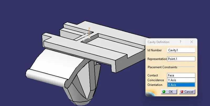
Create cavity connection point:
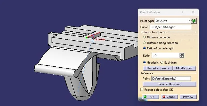
Create cavity connection axis system and orientation should be same as in connector:
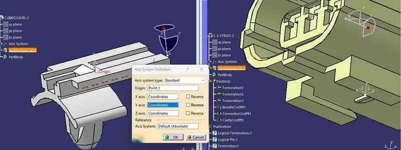
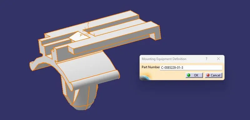
In CATIA Electrical Part Design,
Define the part as a Mounting Equipment:
Cavity Defenition:
FINAL ELECTRICAL ASSEMBLY DESIGN
import the connector, mounting clip, and cavity.
Choose the connector, followed by the cavity and Defining Eelectric connection.