Week 9 - Project - A pillar Design with Master Section
AIM:
- To create B side features for the A surface using the master section given to us as an input.
- To create main and side core tooling axis for A pillar and its B side features.
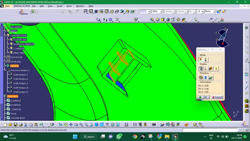
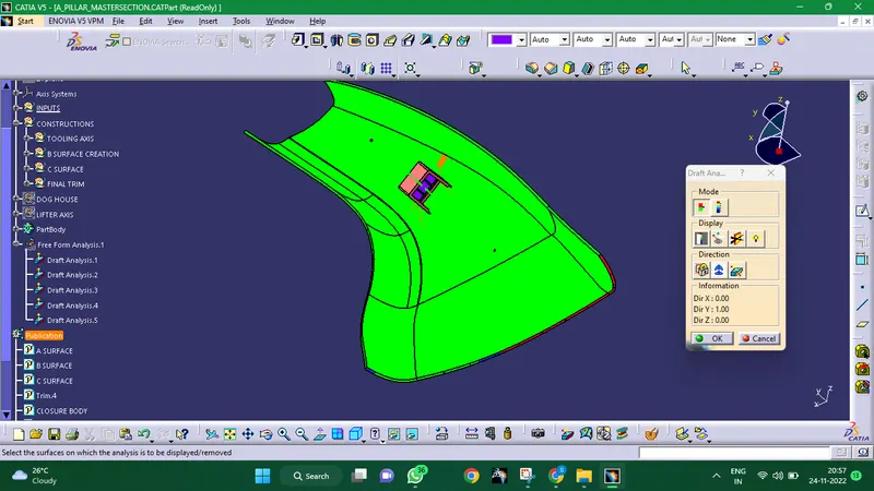
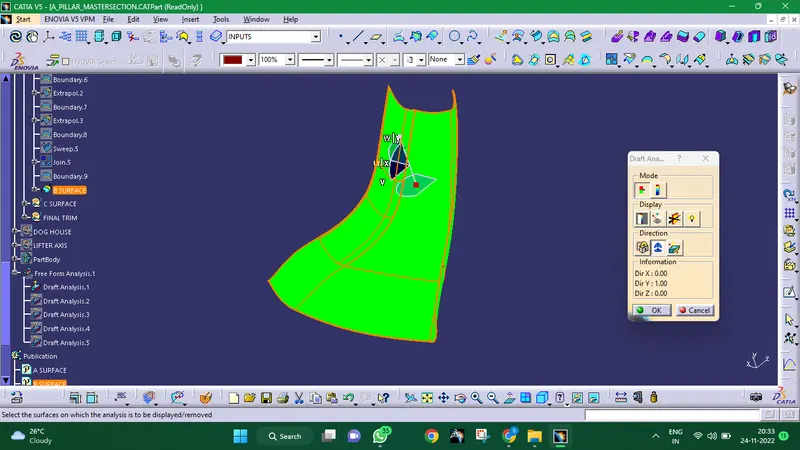
- To do the draft analysis of the overall model of the A pillar i.e including B side features.
INTRODUCTION:
MASTER SECTION:
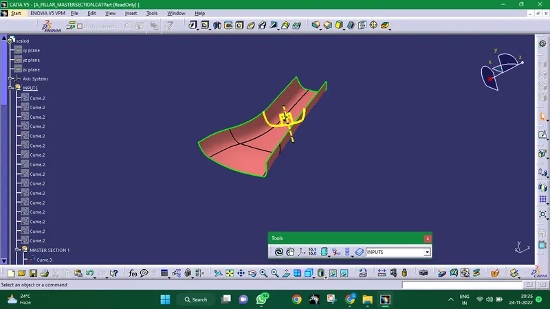
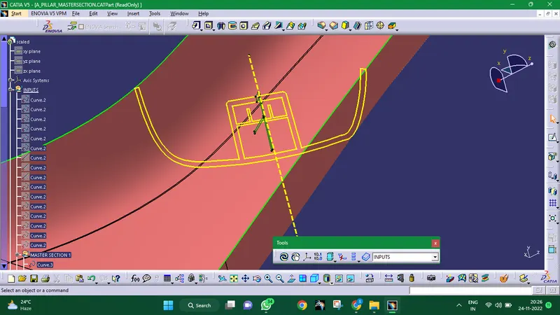
The stages of the product life cycle known as feasibility check and concept validation are when master portions are developed. Following the development of the concept design, i.e. class A surfaces, these are often the guidelines for design criteria and which determine the component packaging.Before translating the concept design into a reliable 3D engineering design, the master section enables us to determine the concept design's viability, clearances, packing, and attachment strategy.
The evaluation of the master section performance during the vehicle concept design phase primarily relies on the reference vehicle data and expertise of the structure design engineer.
DESIGNING:
MAIN AND SIDE CORE TOOLING AXIS CREATION:
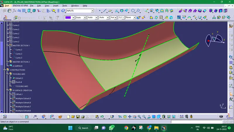
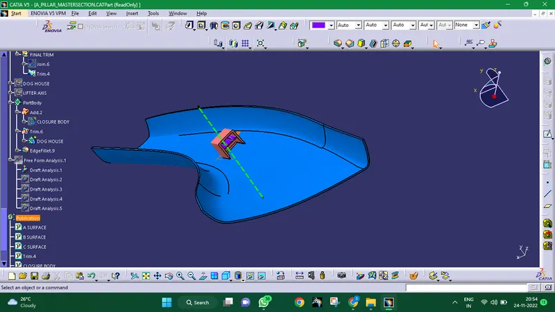
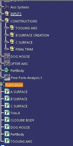
As all attachment features contain a significant number of surfaces parallel to the tooling direction, we also need to take the attachment features on the B side into account in addition to the A surface and C surface when constructing the tooling axis.We can use the master sections of the B side features as a guide for designing the tooling and create the tooling axes as necessary.We employ the bisecting method to build the tooling axes, noting the lines that appear to cause issues with the moulding as we go. And an expanded duplicate line is made from it. In addition, we use draught analysis to assess the viability of the tooling direction after creating another bisecting line.
DRAFT ANALYSIS:
CREATION OF CLASS B SURFACE:
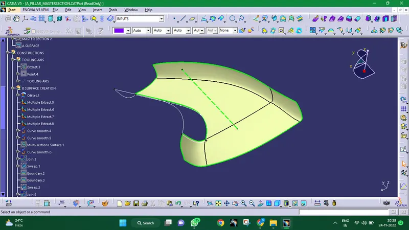
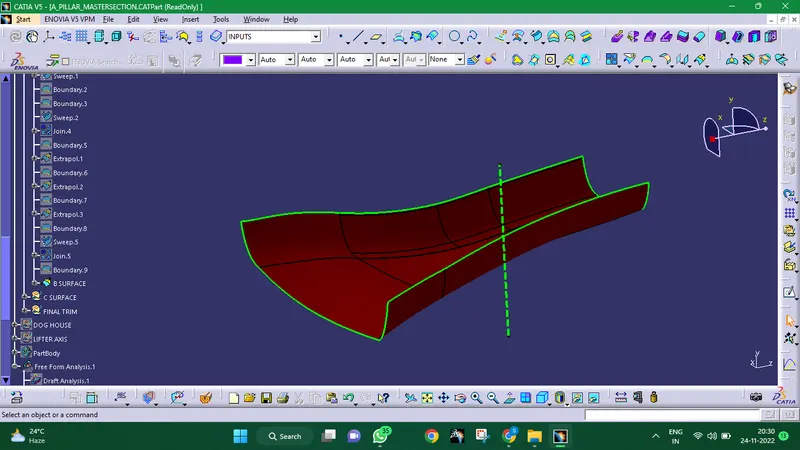
We will give the class A surface an offset value of 2.5 mm in order to create the class B surface because the part requires a thickness of 2.5 mm, as seen from the master section. After using the offset command, we'll notice that some of the surface's patches are not generating, so we must re-generate them using the multi-section surface command. We will obtain the class B surface by fusing the recreated patches with the offseted surface.
CREATION OF CLASS C SURFACE:
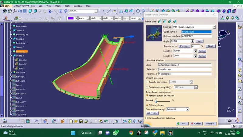
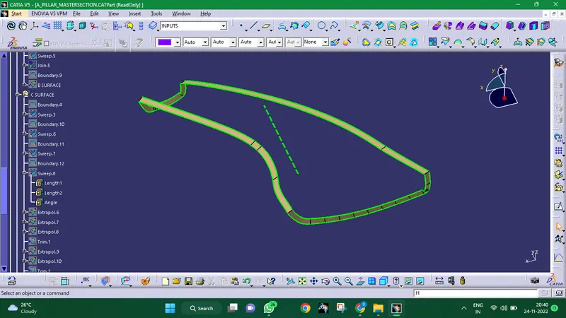
Using the sweep command with the "with reference to draft" option and a 3 degree draught angle, extract the side, front, and rear edges of the class A surface. Use the multi-section surfaces command to create surfaces for the remaining edges that are consistent with the major surfaces produced by sweep. The join command can be used to connect all of the surfaces.
CLOSED BODY:
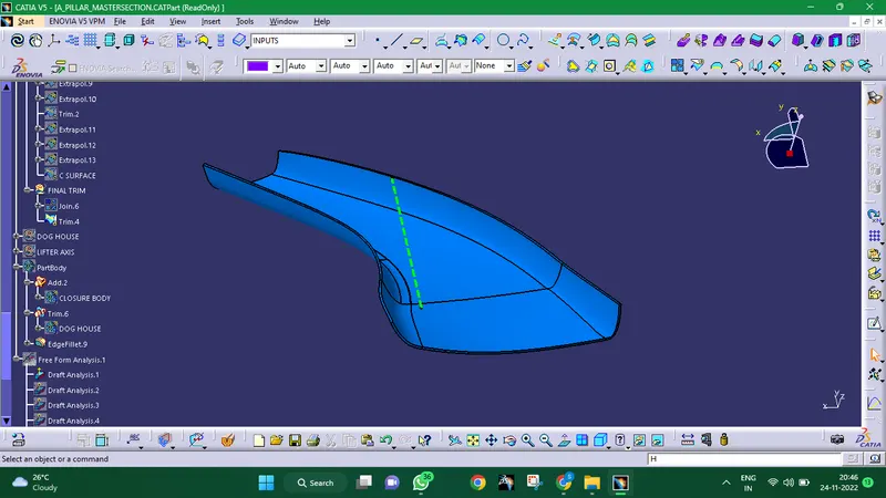
Connect the class A and class C surfaces. With class C surface, trim the obtained surface. We end up with the closed shell body of an A pillar as the trim. In the part design workbench, use the closed surface command to convert the shell body into a part body.
CREATION OF B SIDE FEATURES :
DOG HOUSE:Dog houses are primarily used to prevent sink marks on the A surfaces, particularly in areas where other attachment features, like screw boss, are attached. Placing such features, like screw boss, in that specific region would increase the component's thickness and cause an uneven cooling of the molten plastic during moulding, which would cause the body to shrink from the outside in.
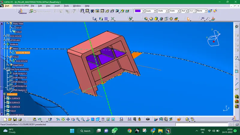
The master sections are used only in the construction of the doghouse. To begin, we draw lines by using the master section's references, which are then extruded along the side core axis to produce the doghouse's wall surfaces. We could get the shape of the dog home by repeating this process for the four sides and trimming them.
Utilizing the thicken command in the component design workbench, you may add material to the trimmed surface. Ensure that the thickness is given in accordance with the doghouse master section.
We can also use the split command to divide the excess or undesirable material portion and give the doghouse the correct shape in accordance with the master section.
The reduction in thickness must not be less than 40% of the wall thickness.
Every face of the doghouse has a drafting angle of 3 degrees, while some faces had their angles reduced to as low as 0.3 by taking the part's thickness into account. All edges must have a fillet value of at least 0.25mm.
A sketch of the cutout is made for the doghouse's top surface, and a pad is made for it. The pad is then removed from the doghouse using boolean operation.
A similar technique was chosen to treat the ribs inside the dog house by extracting, extruding, and thickening the desired lines.
DRAFT ANALYSIS: