Project 2
BACK DOOR WIRING HARNESS
AIM
To Route the Wiring harness on Given car body and Prepare flatten view drawing in CATIA V5.
INTRODUCTION
Car Backdoor:
The term "back door" or "tailgate" simply refers to the opening and closing of the back of the vehicle.It encircles the back of the car.It gives access to a boot or boot that contains cargo.Hatchbacks, estates/station waggons and liftbacks are characterised primarily by a tailboard that hinges at the roof.A cargo area door or entrance may hinge from the top, side, or bottom.
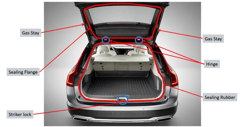
This technique is typically carried out manually in the majority of autos. To open and close the tailboard with the car key, one must exit the vehicle.These days, automakers provide cutting-edge technologies like an automatic tailboard. The electronic closing and opening of the tailboard is handled by an automatic tailboard of a vehicle.
Wiring Harness:
A wiring harness is a collection of wires, connectors, and terminals that are bundled together to provide electrical connections and transmit signals between various components in a vehicle or electrical system. It serves as a central nervous system for transmitting power and information throughout the system.
Wiring harnesses are used in automobiles, aircraft, appliances, and many other electrical devices and systems. They are typically made up of multiple individual wires, each with its own color-coding and labeling for identification and proper connection.
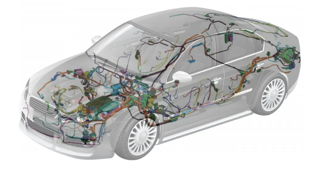
The main purpose of a wiring harness is to simplify the installation and maintenance of electrical components by providing organized and standardized connections. It eliminates the need for individual wiring between each component, which can be time-consuming, error-prone, and difficult to troubleshoot.
Car Backdoor Wiring Harness:
The car back door wiring harness, as previously mentioned, specifically refers to the wiring system that runs through the rear door of a car. It is responsible for providing electrical connections between the car's main electrical system and the components located in the rear door, such as speakers, power windows, central locking system, rear defogger, and other features.
The wiring harness in the car's back door is designed to withstand the constant movement and flexing that occurs when the door is opened and closed. It typically consists of a bundle of wires encased in a protective sleeve, such as rubber or plastic, to prevent damage and ensure insulation.
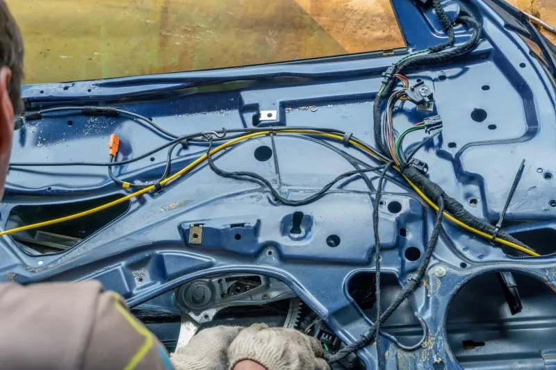
The specific configuration of the wiring harness can vary depending on the make and model of the car, as well as the features and components installed in the rear door. It may include wires for power supply, ground connections, speaker connections, data communication lines, and control signals.
If there is an issue with the car back door wiring harness, it can lead to electrical problems in the rear door components. Common issues include broken or damaged wires, loose connections, or corrosion at the connectors. These problems can result in non-functioning power windows, malfunctioning speakers, or issues with the central locking system.
If you suspect a problem with the car back door wiring harness, it is recommended to have it inspected and repaired by a qualified automotive technician or electrician. They can diagnose the issue, repair or replace any damaged wiring, and ensure proper functioning of the electrical components in the rear door.
PROCEDURE:
- Create an electrical definition for each mechanical connector and save it in the catalogue.
- Put every connector in its proper location on the back door's 3D CAD model.
- P-Clamps and Fir Tree clips should be positioned according to packaging guidelines.
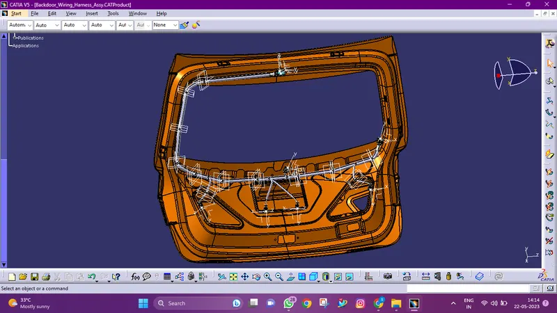
- With all the electrically defined connectors and mounting tools, create the wiring harness routing.
- To generate sub branches and connect to different connections in the geometric bundle, create branching points as necessary.
- As needed, apply protective covers.
- Create a flattening of the wiring harness for the final geometric bundle.
- Create a drawing sheet with the flattened wiring harness using the drafting workbench.
Methodology:
Step 1 :
Download the Backdoor CAD data from the specified source.
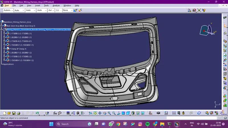
Step 2 :
Download the required Connectors from the source
Mechanical Part into Electrical Part
- Creation of connector connection point:
- Make a midpoint on the contact face for wire bunddle insertion.
- Create an axis system referencing the newly generated point and specifying the axis direction.
- The Y-Axis should be oriented towards the connector's front face.
- The X-Axis should be oriented towards the clip's locking mechanism.
- The Z-axis should be pointing across the connector from left to right.
- Creation of Bundle Connection Point.
- Define the part as a connector and specify terminations.
- Define Bundle connection point.
- Define connector connection point.
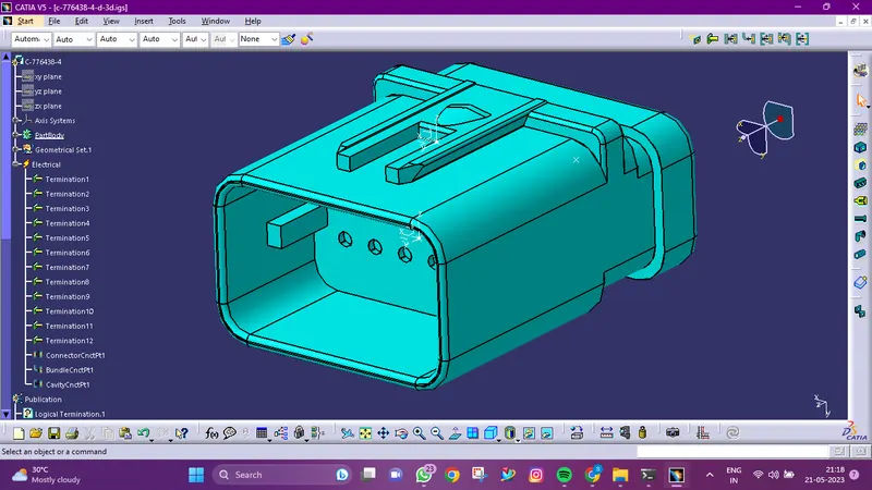
Inter Connection Connector: C-776438-4
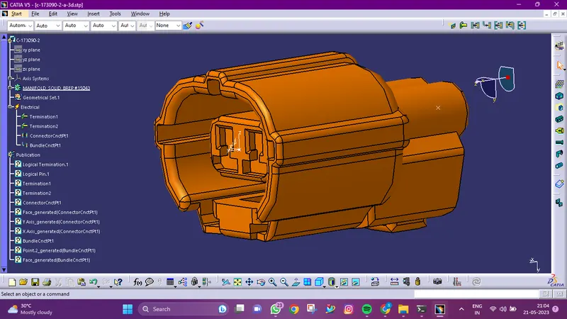
2-pole connector: C-173090-1
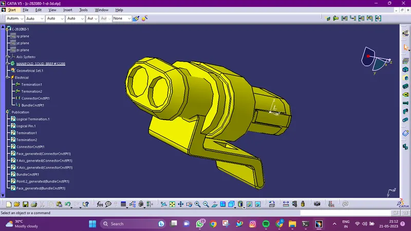
C-282080-1
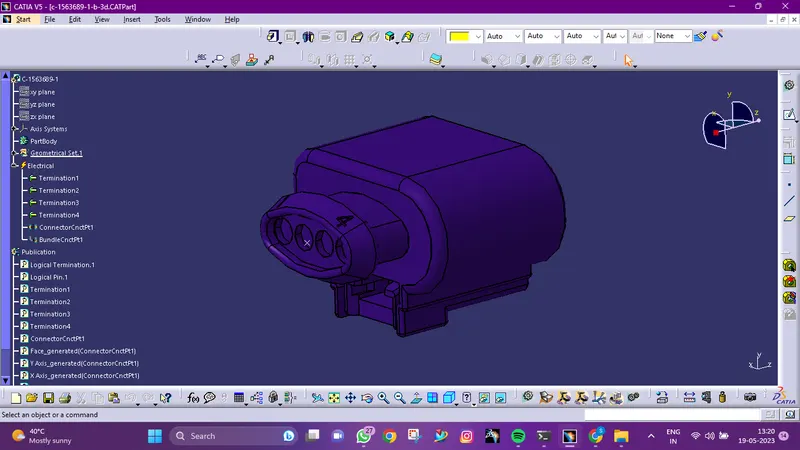
4 pole connector: C-1563689-1
Step 3 :
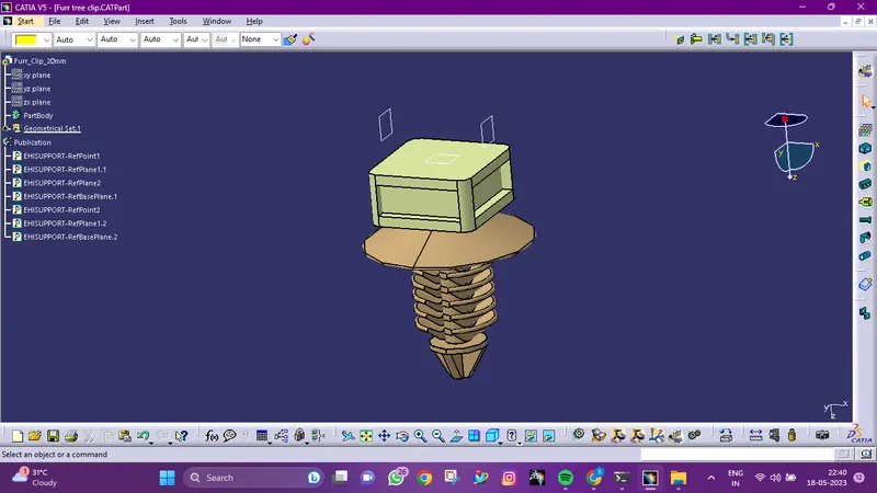
Download the clamps, clips define as electrical support
- Add two points. both as points of admission and exit.
- Create two planes, plus one at the base.
- Change the part design to electric
- Click on support definition, then part selection, entry point selection, entry plane selection, and base plane selection.
- Again Click on support definition, then select part, select exit point, select exit plane, with the base plane being automatically taken as the secondary plane.
STEP 4 :
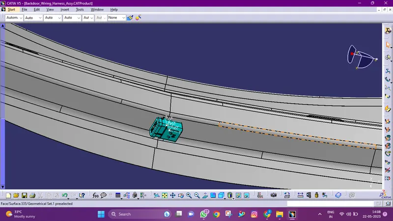
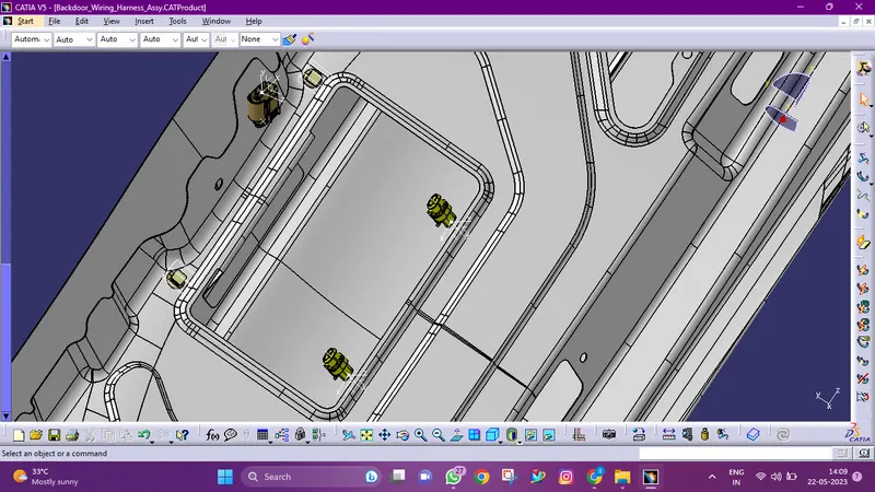
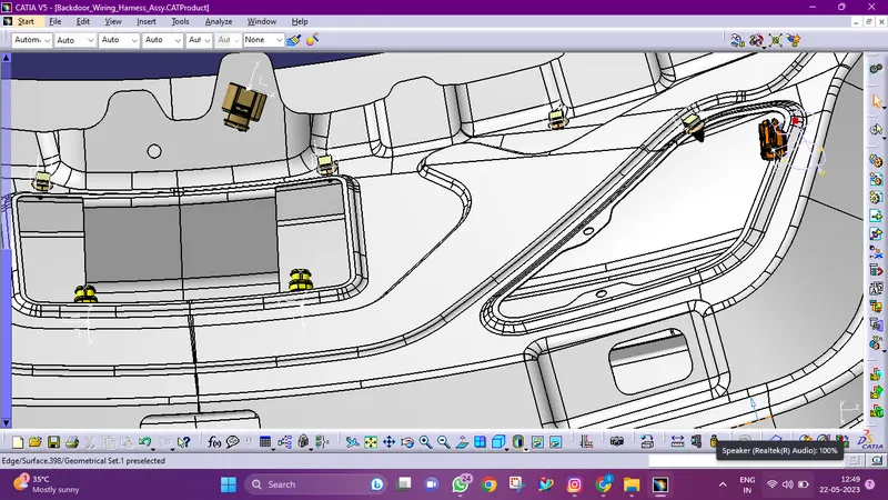
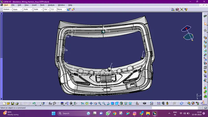
Placing the connectors to the required locations
STEP 5 :
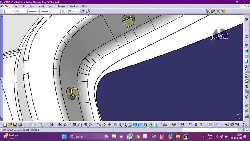
Adding the furr tree clip to the locations
Step 6 :
ELECTRICAL HARNESS
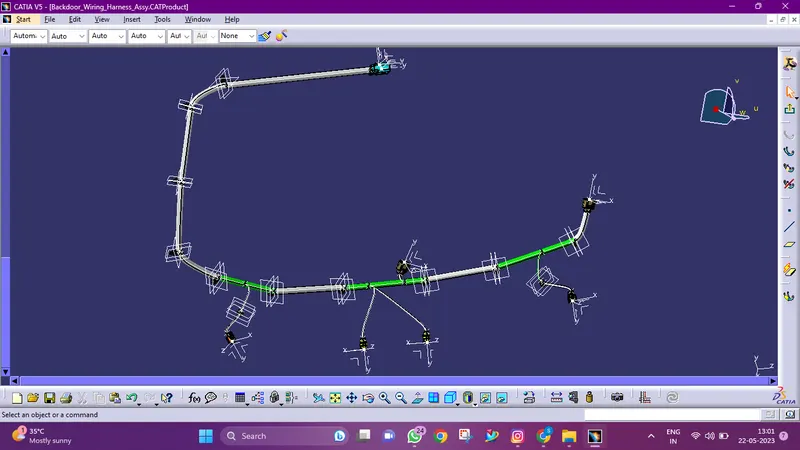
The assembly should have electrically defined connectors and be positioned on the backdoor appropriately.Place the supporting mounting clips in the back door after the connectors are in place to ensure proper routing without entangling the bundle with adjacent components.After completing this route, ensure sure the bundle segment does not collide with the surrounding components.After the geometric bundle is complete, flatten it and check the wiring harness for bundle connectivity.
Step 7 :
Checking the Bundle continuity
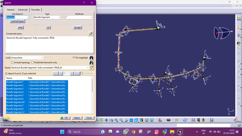
- Make sure multi-branchable is first chosen, then proceed to Edit > Search > Advanced > Workbench > Electrical > Type > Bundle Segment > Attribute > Fully Connected.
- The 'True' option will display all linked bundle segments, whereas the 'False' option will display all disconnected bundle segments.
- In this case, we chose the 'True' option and ran a search.
- As illustrated in the below image, all of the bundle segments are highlighted to show that they are all electrically connected.
Step 8 :
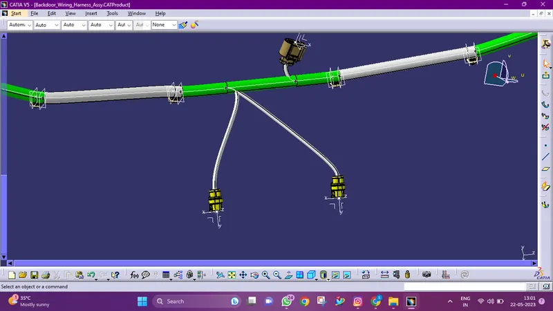
Adding protective coverings
For the car backdoor, we completed the entire wiring harness layout. The top shell of the guiding channel as well as all bundle segments must now be covered with protective materials.
Step 12 :
Note: Due to some visibility issue with my catia software the supports ( Fir tree clips) are not visible, im submitting all the requried details below:
Flatten view
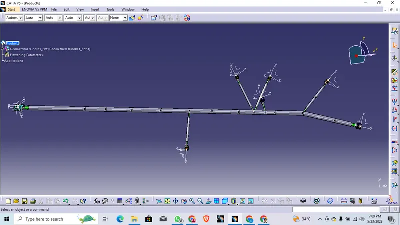
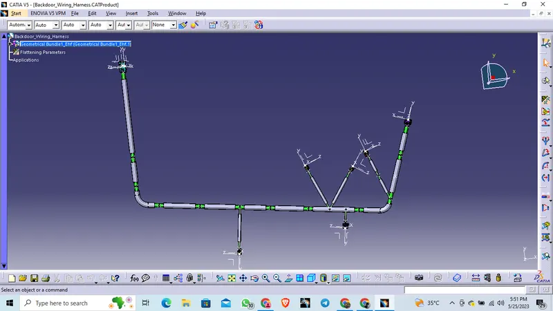
- We must use Catia V5's Electrical Harness Flattening Workbench to create flat views.
- Additionally, we must ensure that the flattening file is saved in the same directory as the other harness assembly files.
- We must first declare the flattening parameters.
- In order to flatten the file along the face of the interconnection connector, we first extracted the bundle assembly into the back door Harness Flattening Product file.
- At this point, the flattening diagram of the plastic guiding channels has been removed from the drawing view for the sake of clarity.
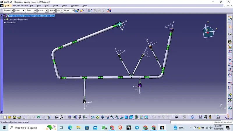
Synchronization details:
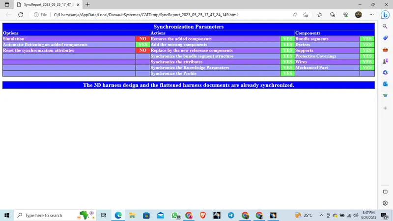
Here in component section Supports are Correctly mentioned.
Step 10 :
Drawing Sheet
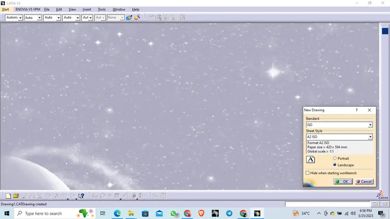
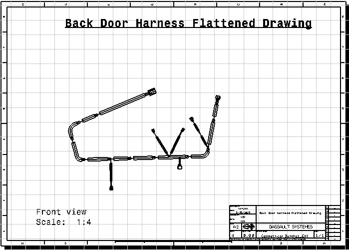
- Make a drawing file for the harness product that has been flattened.
- First, we must ensure that bundles and protective covers have distinct graphical representations in the flatten parameter settings
- Single-line illustration of bundle segments
- Coverings used as protection - Double line illustration.
CONCLUSION:
In conclusion, designing and routing a wiring harness on a car body requires careful planning and attention to detail. Following packaging rules and industry best practices is crucial to ensure safety, efficiency, and durability. Applying protection coverings as required will prevent damage to the wiring. With the use of CATIA V5 software, a high-quality design with a flatten view drawing can be achieved. Overall, this project highlights the importance of adhering to industry standards and guidelines to optimize the performance and longevity of the wiring harness