Wiring harness design in CATIA V5 - 3D modeling Week 5 & 6 Challenge
Wiring harness design in CATIA V5 - 3D modeling Week 5 & 6 Challenge
AIM
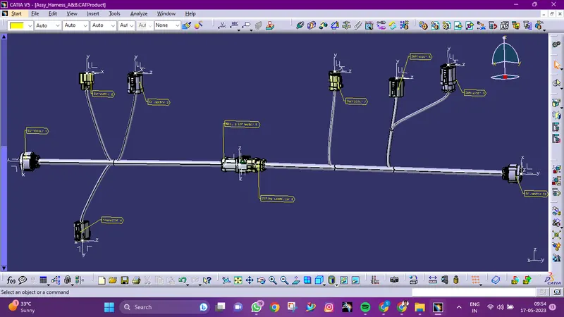
Route the following harness layout in Electrical workbench. Make assumption for harness bundle diameters. Use the connectors provided. After completion of routing,
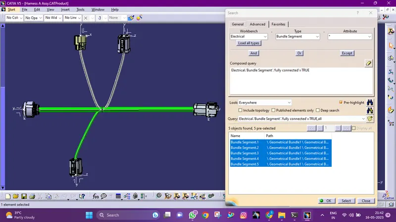
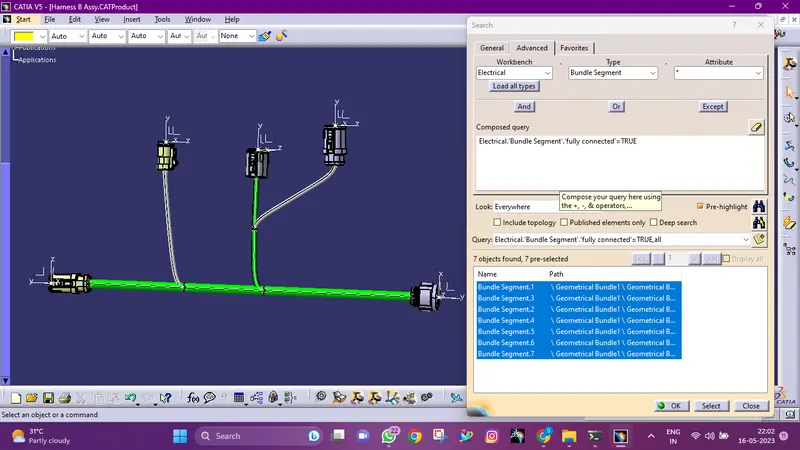
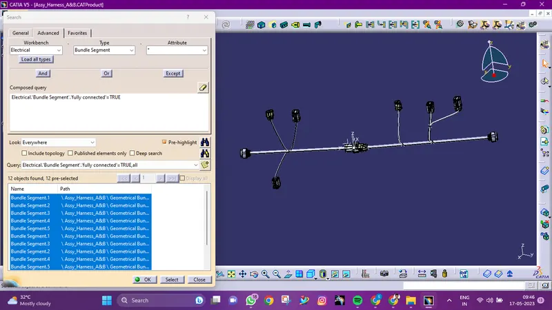
- Check the bundle Continuity. Add snap of result in submission
- Add annotation to all connectors. Make an assumptions for annotations like connect 1, 2 etc
- Check for the bundle warning. Add snap.
- Generate CAT.part of harness assembly and convert is in. igs format.
PROCEDURE
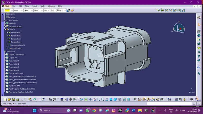
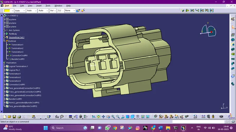
Mechanical Part into Electrical Part
- Creation of connector connection point:
- Make a midpoint on the contact face for wire bunddle insertion.
- Create an axis system referencing the newly generated point and specifying the axis direction.
- The Y-Axis should be oriented towards the connector's front face.
- The X-Axis should be oriented towards the clip's locking mechanism.
- The Z-axis should be pointing across the connector from left to right.
- Creation of Bundle Connection Point.
- Define the part as a connector and specify terminations.
- Define Bundle connection point.
- Define connector connection point.
Harness A Connectors
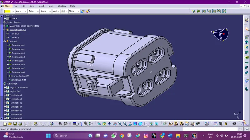
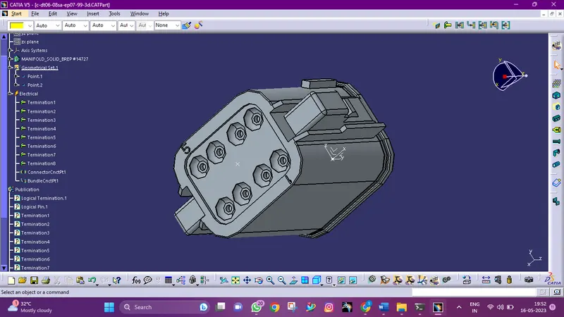
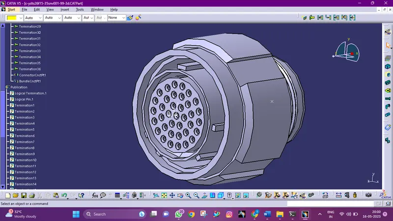
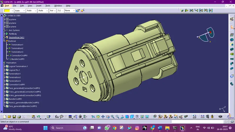
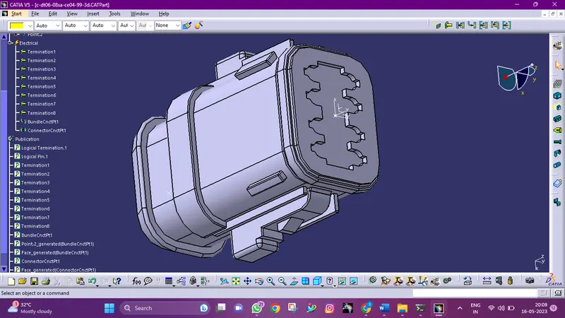
Harness B Connectors
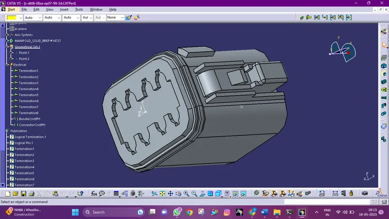
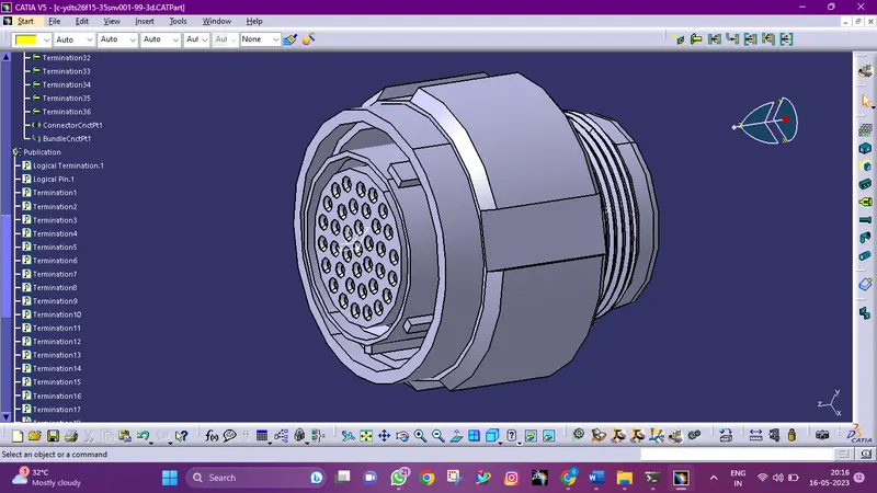
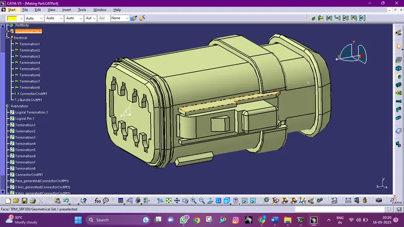
Locate the connectors in their desired position
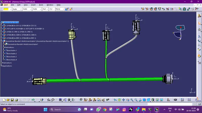
The workbench was changed to Electrical Harness Assembly after all the connectors had been defined, and Geometrical Bundle was then turned on. With the help of the Multi-Branchable Document command, all of the connectors were routed.
Bundle diameter is assumed to be 10mm, 5mm.
Harness A
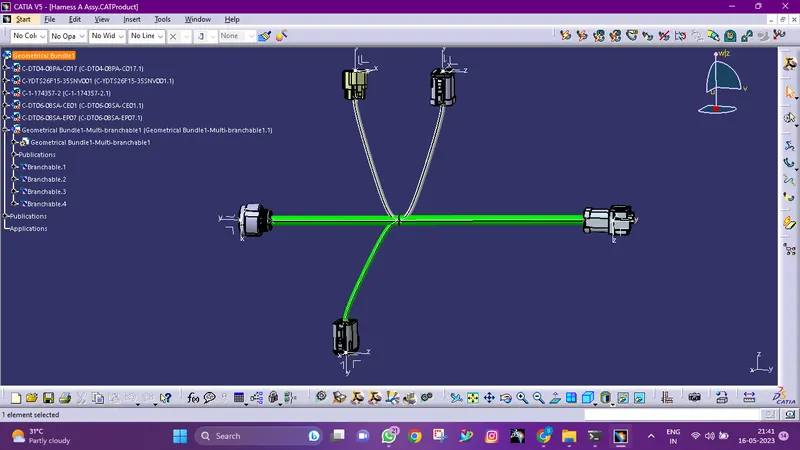
Harness B
Connectivity Check
Annotation