Week 8 - Challenge 2 - Switch Bezel Design
AIM:
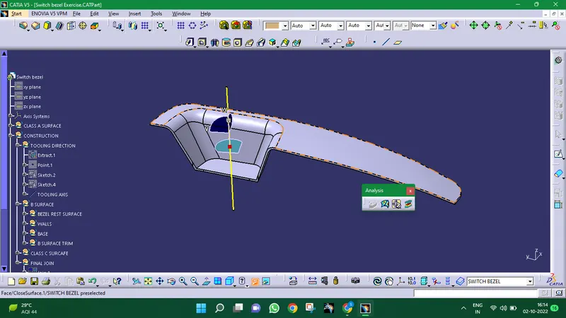
To create the Switch Bezel Plastic component through the given Class-A surface. To begin with, the tooling axis for the given Class-A Surface should be created meeting the requirements of the draft angle and at the end perform the Draft analysis on the model.
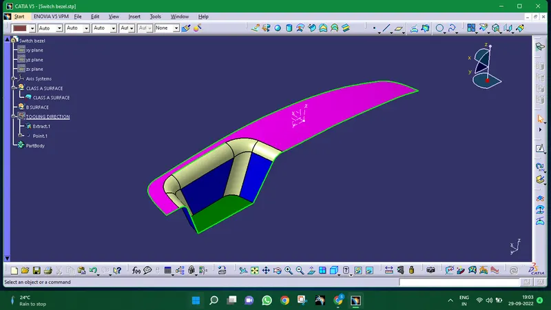
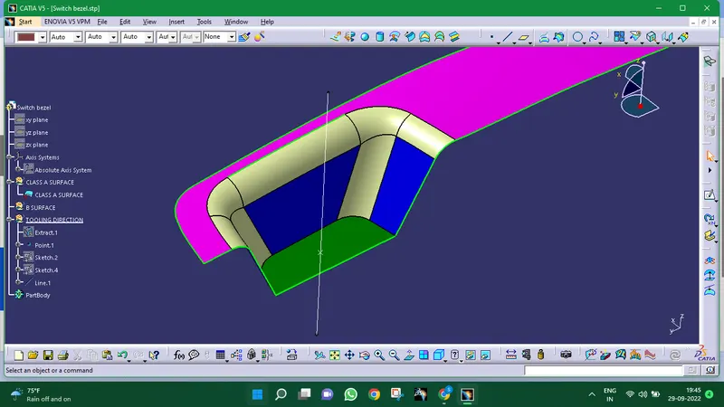
Given Class A Surface :
Creation of Tooling Direction:
TOOLING AXIS:
By taking into account this tooling axis, the draught angle that is required to be provided is nothing more than the direction in which the mould opens and shuts. The bisecting technique allows us to make a tooling axis.
BISECTING METHOD:
This technique is used to generate tooling axes for that purpose. First, the direction of moulding must be decided. Next, a dummy tooling axis is created for the purpose of reference.With this approach, we pick the surfaces that could cause issues and consider intersections in the x and y directions. Using these curves, we create two lines, from which we create a bisecting line in both the x and y directions.Tooling axis cleaning x-direction and tooling axis clearing y-direction are the terms used to describe how the clearing is carried out.
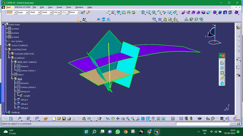
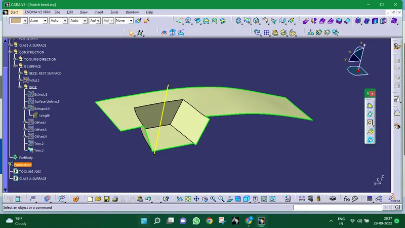
Creation of Class B Surface:
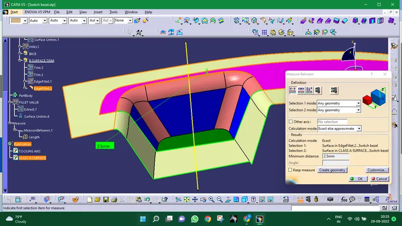
Thickeness of 2.5mm:
Creation of Class C Surface:
Applying sweep defention to the body for creation of class c surface
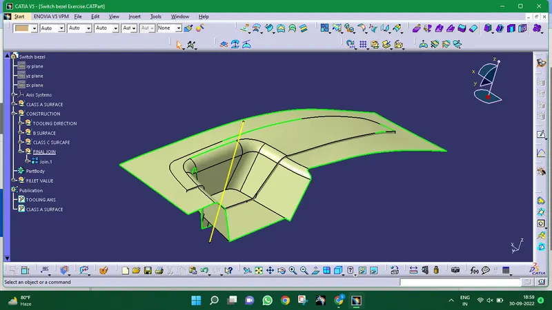
Trim the unwanted surface for the final join
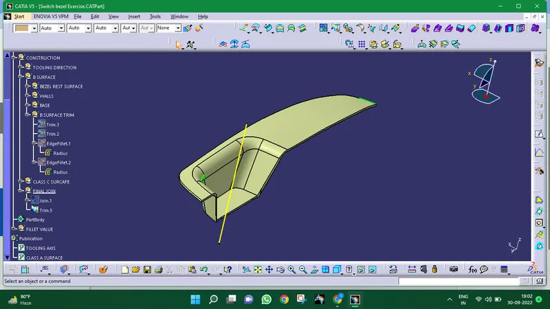
CLOSED SURFACE
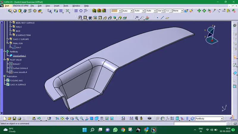
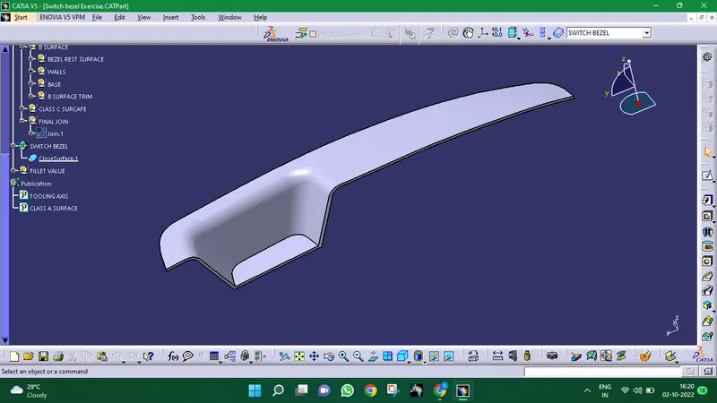
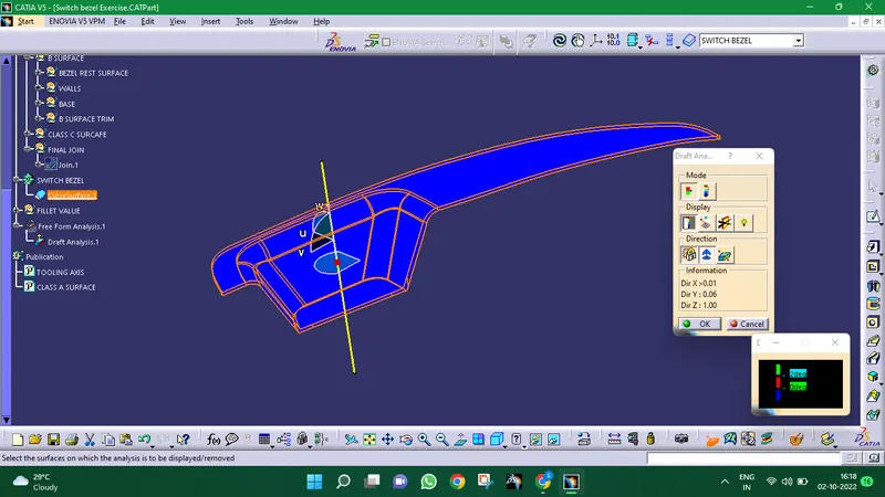
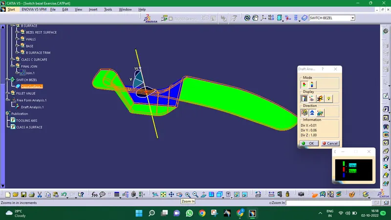
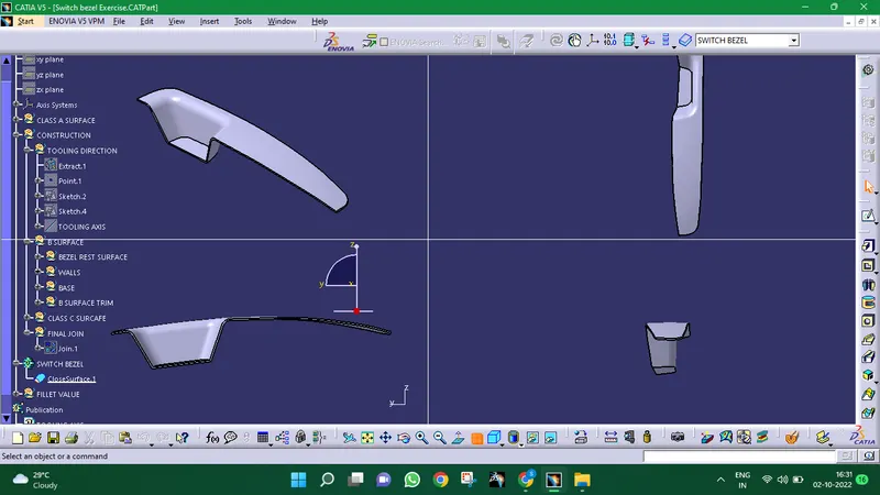
Solid model with the proper color code of the draft angle in various orientations (Isometric, Front, Side, and Top View):
DRAFT ANALYSIS:
DRAFT:
Draft angle is nothing more than giving the part a tapered area for simple release from the mould during manufacture. This is notably done when designing plastic components with complicated shapes. Although it typically has a 3-degree draught angle, it can change depending on the component that needs to be constructed.