Week 2:- BiW Fixture Basics Challenge
What is the process of project execution activity?
Answer:
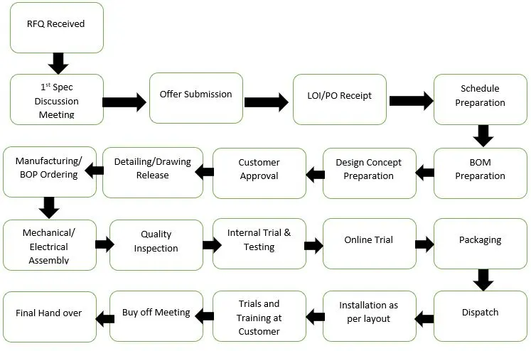
RFQ
The fixture design project in BIW starts. It all begins with the bare minimum requirements or RFQs that we get from customers. Request for quotation (RFQ) is the term used when a customer submits their requirements, specifications, etc. in the form of a document or data for us to review or process. Information included in this document or data includes things like technical offers, commercial offers, and project timelines.
First meeting to discuss specifications and submit an offer
The project's execution timeline and documentation relevant to the technical and commercial offers are prepared in this. The time needed for 3D design, design analysis, drawing and detailing, manufacturing, assembly, and commissioning, among other things, is taken into account. The cost of every procedure is then taken into account. The offer is developed and presented to the customer after taking these factors into account. Below is a diagram that demonstrates how a technical offer is made.
PO/LOI
Once we have submitted our offer, the customer will review it while also receiving offers from several suppliers and vendors. He weighs the costs of numerous technical proposals and chooses the one that best meets his needs. Then he will issue the LOI or PO with the previously stated terms and conditions.
Making a schedule
Each activity in a project depends on the one before it. Therefore, if the prior activity did not finish on time, the next activity's date will be delayed and it will not proceed. Each action has a designated time, such as when it begins and when it ends. As a result, we have several backup plans so that the final date coincides with the delivery date. To finish the job on schedule, effective scheduling must be done. One of the most important demands made by customers is on-time delivery. They also expect their time commitments to be honoured.
Prepare the BOM
When a BOM is being prepared, a part list that comprises purchased parts, vendor parts, and consumable goods along with their respective quantities is listed down. Budget for the BOM preparation materials will be set. Motor, gearbox, cylinder, pneumatic & hydraulic valves, etc. are some examples of 8/0 parts. Additionally, vendor components consist of all machined, fabricated, etc. parts, while consumables include of things like oil, grease, glue, Loctite, etc.
Design Concept Preparation
The next stage is to create a concept. An idea is built on everything. specification received customer data in the form of 3D car panel data, drawings, and standard drawings. Manufacturing standards, design standards. All data design concepts are built after study.
Customer Approval
When a design concept is finished, it is sent to the client for approval. This procedure is sometimes referred to as the design approval process (DAP) or the client approval process. The customer will then verify whether or not all of his criteria are taken into consideration. Only if it is in accordance with the technical offer given will he approve the prepared concept. The customer will bring up some issues. The project team updates the design team on these adjustments. Once more, the design team works on it. Some modifications or changes are required to improve the design, such as improving the clamping so that this mechanism will function properly and using this brand of sensor. The customer is once more informed of these modifications. After receiving his final clearance, work on the detailing and drawing will continue.
Drawing Release
When breaking down each assembly into its component parts, each assembly is separated into standard and manufactured for standard parts, and each part has its own data sheet or specification sheet prepared to purchase it from a catalogue. These specifications include the motor power, motor current, rising torque produced, and shaft rpm that are appropriate for our application. Details on the parts should be sent to the vendor in degrees. Drawings should include information about surface fish surface treatment hardness welding as well as all part dimensions with tolerance. Finish, surface treatment, hardness, and welding comment all need to be mentioned on these drawings. These drawings have been reviewed and approved for manufacture.
BOP Ordering
All of the drawings necessary to begin producing goods like Mylar, blades, risers, and base frames will be given to the manufacturing department. Additionally, the buying team will order B/O components such motors, gearboxes, cylinders, and valves. As the materials are prepared, the QC team should check that every component is received in accordance with the specifications, as failing to do so can cause problems later and waste our time.
Mechanical & Electrical Assembly
Parts are available for assembly after the QC inspection. A station is the integration of every mechanical and electrical component. The assembly team will complete every step of the assembly according to the drawing. Every station is constructed in accordance with the layout. The quality control team should thereafter be involved in verifying that the assembly is in accordance with the final drawing and that all coordinate dimensions are accurate.
Internal Trial & Testing
Internal trials and testing began following the QC team's approval. The assembly must be physically placed in the fixture in the initial phase to ensure that it is being fixed correctly, that the clamping is satisfactory, and that loading and unloading of the part is simple. Additionally, the operating height is examined and found to be ergonomically sound. Then begin testing the fixture for the viability of welding and the approachability of the gun in the fixture. then try it out online.
Online Trial
Online training is the next stage after a successful trial. There are two modes for online training: manual and automatic. The control panel is used to operate the online trial system. Testing should be done on every sensor, actuator, motor current and temperature, noise, alert, and safety. Each process must be carried out according to plan, and cycle times must be met. Online training systems run for specific cycles and actual production is used to guarantee system operation.
Packaging
After the test is successful, the client approves the dispatch system. System must be disassembled station by station and packed appropriately before being dispatched. Packing delicate items carefully is essential to prevent damage to their appearance or functionality while in transit. To convey the message of using caution when handling and transporting by air, additional handling instructions should be printed on specific parts during packaging labelling.
Dispatch
Everything brought to the customer's location through railways, containers, ships, or installations: The entire system is put together, installed, and approved in accordance with the DAP-approved layout at the customer. All stations, robots, and conveyors are installed at the distances indicated in the scheme. Robot arm should be able to be picked up and dropped off at the station. It should not interfere with other robot arms, and it should be capable of being picked up and dropped off at stations. It shouldn't interfere with other machinery.
Trial and Training at Customer
After installation is complete, customer-side testing begins. Therefore, there will be online and production trials. Production trials are required because, while developing the fixture, it was determined how many units will be produced from it and whether they would meet quality standards. Additionally, according to the technical proposal, 100 units will be produced from one fixture in an 8-hour shift with high-quality welds. Therefore, fixture capability will be guaranteed throughout the production trial.
Buy off Meeting
After the training is over, the customer and project team meet to discuss whether any more elements need to be added and whether anything from the LO/PO or offer submission is missing. Then the customer will make a complaint or occasionally request a change, which will result in an additional quotation and additional costs based on the completion of the task as agreed upon in the meeting.
Final Hand over
Once the customer's concerns have all been addressed, the final handover will take place. The customer will receive all data, technical manuals, and soft and hard documentation. These are the primary project tasks.
What are the types of joining processes?
Answer:
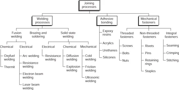
There are several types of joining processes used in manufacturing and construction to connect or join different materials together. Some common types of joining processes include:
1. Welding: Welding involves melting the edges of two or more materials and allowing them to fuse together. It is commonly used for metals and thermoplastics. Various welding techniques include arc welding, gas welding, spot welding, TIG (Tungsten Inert Gas) welding, and MIG (Metal Inert Gas) welding.
2. Brazing and Soldering: Brazing and soldering are similar processes that use a filler material with a lower melting point than the base materials. The filler material is heated and flows between the joint, creating a bond when it solidifies. Brazing is typically used for high-temperature applications, while soldering is used for low-temperature applications.
3. Adhesive Bonding: Adhesive bonding involves the use of adhesives or glues to join materials together. The adhesive creates a bond between the surfaces of the materials, providing strength and stability. Adhesive bonding is often used for joining materials such as plastics, composites, and some metals.
4. Mechanical Fastening: Mechanical fastening refers to joining materials using mechanical means, such as screws, bolts, nuts, rivets, and clips. These fasteners provide a secure connection and can be easily assembled or disassembled when necessary. Mechanical fastening is commonly used in construction, automotive, and aerospace industries.
5. Riveting: Riveting involves joining materials by deforming a metal pin or rivet to hold the materials together. The rivet is inserted through holes in the materials and then secured by deforming or forming a head on one end. Riveting is often used for joining metal sheets and structures.
6. Clinching: Clinching is a cold-forming process that joins materials by deforming the materials locally. It involves pressing two or more layers of materials together, creating a mechanical interlock without additional fasteners or adhesives. Clinching is commonly used for joining sheet metals.
7. Mechanical Interlocking: Mechanical interlocking involves designing the joint in a way that the shapes or features of the materials mechanically interlock with each other. This can be achieved through interlocking tabs, slots, or other features that provide a secure connection.
8. Fusion Bonding: Fusion bonding is a process that involves melting the surfaces of materials to be joined and allowing them to fuse together. This is typically done with thermoplastics, where the heated surfaces are brought into contact and cooled to solidify the joint.
These are just a few examples of joining processes, and the selection of the appropriate joining method depends on factors such as the materials being joined, their intended application, desired strength, and environmental conditions.
What is Resistance Welding & its application in the automotive sector?
Answer:
Resistance welding is a joining process that uses the application of heat generated by electrical resistance to create a bond between two or more materials. It involves the passage of an electric current through the materials to be joined, causing localized heating at the interface, and subsequent fusion or solid-state bonding. The heat is generated by the resistance encountered by the electric current flowing through the materials.
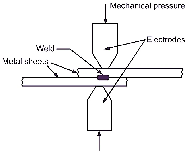
Resistance welding is widely used in the automotive sector due to its efficiency, speed, and reliability. Some common applications of resistance welding in the automotive industry include:
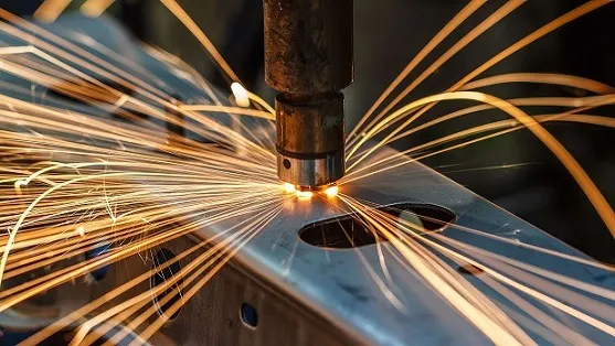
1. Spot Welding: Spot welding is one of the most commonly used resistance welding techniques in the automotive sector. It involves creating a series of spot welds at specific points to join two or more metal sheets together. Spot welding is widely used for joining automotive body panels, such as the chassis, roof, doors, and trunk.
2. Seam Welding: Seam welding is a variation of spot welding that creates a continuous weld along the length of a joint. It is commonly used for joining fuel tanks, exhaust systems, and other components that require leak-tight and continuous welds.
3. Projection Welding: Projection welding is used to join materials with raised or embossed features, such as nuts, studs, or wires, to metal sheets. This technique is often employed for joining brackets, fasteners, and electrical components in automotive assemblies.
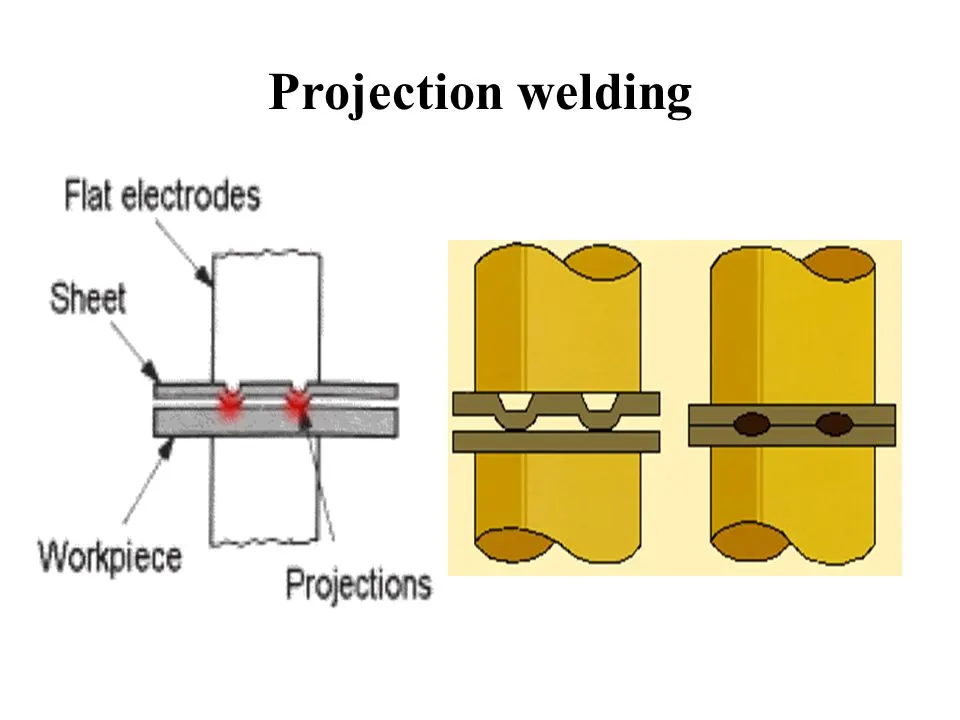
4. Flash Butt Welding: Flash butt welding is a resistance welding method used for joining metal bars or rods end-to-end. It involves heating the ends of the rods by passing a high electric current through them and then applying pressure to forge them together. Flash butt welding is used in the manufacturing of automotive components such as axles, drive shafts, and suspension parts.
5. High-Frequency Resistance Spot Welding: High-frequency resistance spot welding is a variation of spot welding that uses higher frequencies to generate heat more quickly and precisely. It is used for joining lightweight materials, such as aluminum alloys, commonly found in automotive body structures.
The advantages of resistance welding in the automotive sector include fast production cycle times, high productivity, repeatable and consistent quality, and the ability to automate the process for high-volume manufacturing. It is a preferred joining method in automotive assembly lines due to its cost-effectiveness, robustness, and suitability for joining a wide range of materials commonly used in vehicle construction.
What is fusion welding & types of fusion welding with its application in the automotive sector?
Answer:
Fusion welding is a joining process that involves melting and fusing the materials to be joined to create a strong bond. It typically requires the application of heat to reach the melting point of the materials, allowing them to mix and solidify into a single joint upon cooling. Fusion welding is commonly used in the automotive sector for joining various metal components. Here are some types of fusion welding used in the automotive industry:
1. Gas Metal Arc Welding (GMAW/MIG): Gas Metal Arc Welding, also known as Metal Inert Gas (MIG) welding, uses a consumable electrode wire and a shielding gas to protect the weld pool from atmospheric contamination. It is commonly used in the automotive industry for joining metal sheets, frames, and components with high welding speeds and good control over the process.
2. Gas Tungsten Arc Welding (GTAW/TIG): Gas Tungsten Arc Welding, also known as Tungsten Inert Gas (TIG) welding, uses a non-consumable tungsten electrode and a shielding gas to protect the weld pool. It provides precise control over the welding process, making it suitable for welding thin materials, complex shapes, and high-quality welds. GTAW is commonly used in automotive applications such as welding aluminum components, exhaust systems, and fuel tanks.
3. Resistance Spot Welding (RSW): Resistance Spot Welding, as mentioned earlier, is a fusion welding process that uses the resistance heat generated by passing an electric current through the materials to be joined. It is extensively used in the automotive sector for joining sheet metal components, such as body panels, doors, and hoods.
4. Laser Beam Welding (LBW): Laser Beam Welding utilizes a focused laser beam to generate intense heat at the welding point. The laser beam melts the materials and forms a joint upon solidification. LBW offers high precision, minimal distortion, and narrow heat-affected zones, making it suitable for welding intricate automotive components, engine parts, and high-strength steel structures.
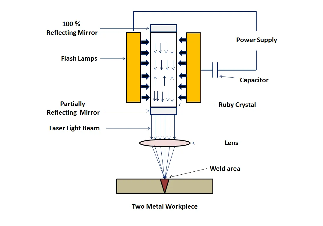
5. Electron Beam Welding (EBW): Electron Beam Welding uses a beam of high-velocity electrons to melt and fuse the materials together. It is a precise and efficient welding method that allows for deep penetration and minimal distortion. EBW is used in the automotive sector for joining critical components such as engine parts, transmission components, and drivetrain elements.
These are just a few examples of fusion welding techniques used in the automotive industry. The selection of the appropriate fusion welding method depends on factors such as the material being welded, the desired strength and quality of the joint, production requirements, and cost considerations.
What is the 3-2-1 principle?
Answer:
The 3-2-1 principle, also known as the Rule of Three, is a basic guideline used in engineering and manufacturing for the design and construction of fixtures or workholding setups. It provides a systematic approach to ensure stability, accuracy, and repeatability when securing a workpiece or component in place. The principle involves three reference points to establish a stable and reliable position for the workpiece.
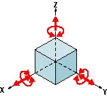
Here's how the 3-2-1 principle works:
1. Three Points of Contact: The first step is to establish three points of contact between the workpiece and the fixture or workholding setup. These points should form a triangle configuration, creating stability and preventing unwanted movement. By having three contact points, the workpiece is effectively constrained in all three dimensions.
2. Two Points of Support: Next, two of the three contact points are designated as support points, providing a stable base for the workpiece. The support points should be positioned in such a way that they prevent rotational or tilting movements. These support points typically act as fixed or rigid supports to hold the workpiece securely.
3. One Point of Location: The remaining contact point, known as the locating point, is used to precisely position the workpiece in a specific location or orientation. This point ensures accurate alignment and repeatability when removing and reinserting the workpiece. The locating point is often associated with a datum or reference feature on the workpiece.
By following the 3-2-1 principle, engineers and manufacturers can achieve proper positioning and secure clamping of workpieces, ensuring stability during machining, assembly, or inspection processes. This principle is commonly applied in various industries, including automotive, aerospace, and general manufacturing, where precision and repeatability are crucial.
Define Body coordinate system?
Answer:
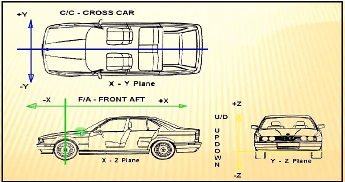
In the context of automotive engineering, the body coordinate system refers to a standardized reference frame used to describe the positions and orientations of various components and measurements on a vehicle's body or chassis. It provides a consistent and universal frame of reference for design, manufacturing, and analysis purposes.
The body coordinate system typically follows a right-handed Cartesian coordinate system, where three mutually perpendicular axes are defined:
1. X-axis: The X-axis represents the longitudinal direction of the vehicle, usually aligned with the direction of forward motion. It extends from the rear of the vehicle towards the front.
2. Y-axis: The Y-axis represents the lateral direction of the vehicle and is perpendicular to the X-axis. It extends horizontally from the driver's side towards the passenger side.
3. Z-axis: The Z-axis represents the vertical direction of the vehicle and is perpendicular to both the X-axis and Y-axis. It extends vertically from the ground towards the sky.
By using the body coordinate system, engineers can precisely locate and measure various components and subsystems on a vehicle. It allows for accurate positioning of features such as suspension points, engine mounts, crash structures, and body panels. This standardization enables effective communication, collaboration, and analysis among different stakeholders involved in the design, manufacturing, and maintenance of automotive systems.
Elaborate Body plane system & its essentials.
Answer:
The reference planes used to define the GD & T of all automobile parts are called body planes. Three planes that are perpendicular to one another make up a body plane in terms of the datum coordinate system.It specifies each product's precise location within the vehicle in relation to a known origin.With established procedures to be followed with various subsystems and primary systems, it facilitates the simple location of various pieces in a vehicle. All designs are carried out in relation to the bodyline.
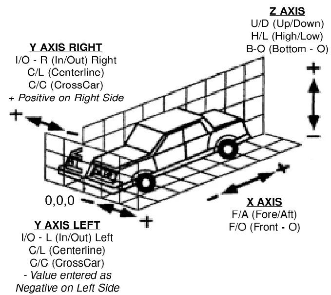
Bodyline dimensions are the measurements from the body planes to the parts.
-
Front O Line (FOL): The FOL represents the front-rear axis or the longitudinal direction of the vehicle. It is an imaginary line passing through the center of the front end and extending towards the rear. The FOL helps define the vehicle's length, and measurements or features related to the front or rear are referenced to this line.
-
Center O Line (COL): The COL represents the left-right axis or the transverse direction of the vehicle. It is an imaginary line passing through the center of the vehicle's body, dividing it into equal halves. The COL helps define the vehicle's width, and measurements or features related to the left or right sides are referenced to this line.
-
Bottom O Line (BOL): The BOL represents the up-down axis or the vertical direction of the vehicle. It is an imaginary line that establishes the baseline or reference for the vehicle's height. Measurements or features related to the height or vertical positioning of components are referenced to this line.
By using these three reference planes, engineers and designers can precisely locate and describe various components, systems, and measurements within the vehicle's body. This standardized coordinate system allows for accurate communication, analysis, and manufacturing processes, as all vehicle drawings and specifications are identified numerically relative to these reference planes.
It is important to note that the actual numerical values or dimensions associated with the FOL, COL, and BOL can vary depending on the specific vehicle or manufacturer's standards. However, the concept of utilizing these reference planes to establish a consistent coordinate system remains the same across the automotive industry.