Week 8 - Challenge 3 - Coin Holder Design
AIM:
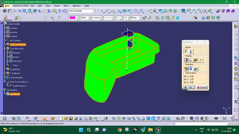
To create the Coin Holder Plastic component through the given Class-A surface. To begin with, the tooling axis for the given Class-A Surface should be created meeting the requirements of the draft angle and at the end perform the Draft analysis on the model.
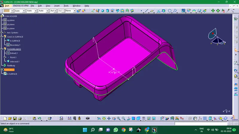
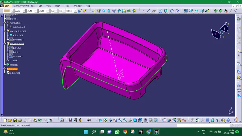
Class A surface:
Creation of Tooling Direction:
TOOLING AXIS:
- By taking into account this tooling axis, the draught angle that is required to be provided is nothing more than the direction in which the mould opens and shuts.
- The bisecting technique allows us to make a tooling axis.
BISECTING METHOD:
- Determine the plane on which we must do the majority of the operations, then build the plane or axis on the component area and specify its direction using a dummy tooling axis.
- Get an intersection sketch by intersecting the class A surface with that plane.
- Find the inclined line profile that may cause a problem, extract it, then expand it using the line command.
- Then, using reference to the lines we've stretched, draw a bisecting line that will serve as our main tooling axis.
- In this instance, we created the Y direction and tooling axis with reference to the base surface.
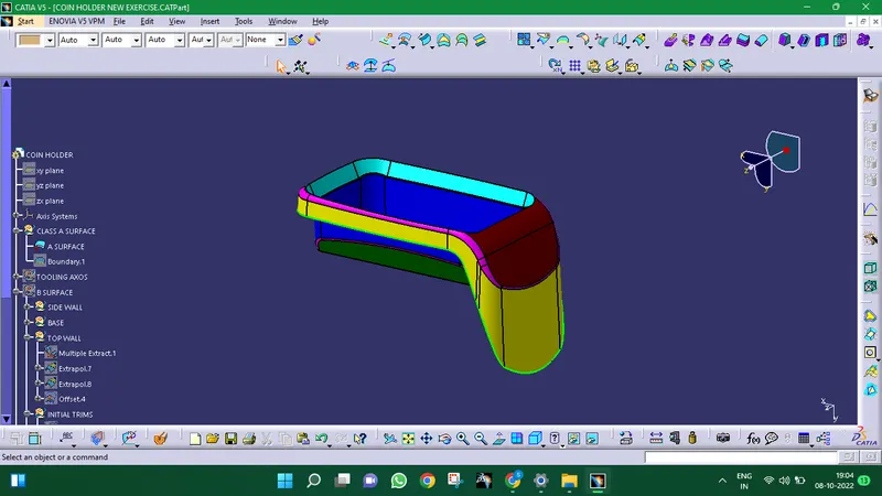
Creation of CLASS B SURFACE:
- For Class A, the surface below is referred to as the core, while the surface above is referred to as the cavity
Class B is an engineering surface, while Class A is an aesthetic surface. - The class A surface must to be inside the B surface.
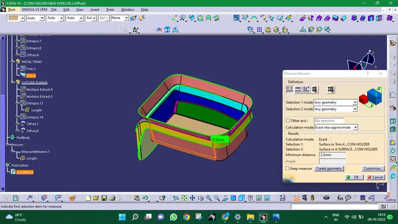
- B surface can be separated into four surfaces: the base surface, outer flange, top walls, and side walls.
- These surfaces can then be combined and trimmed.
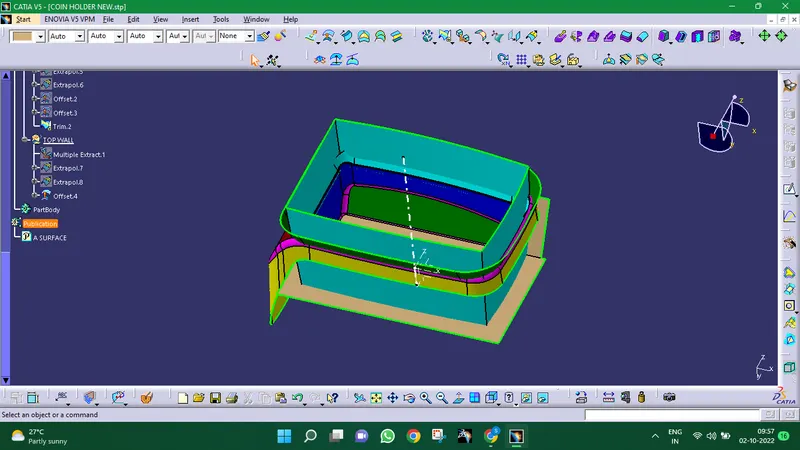
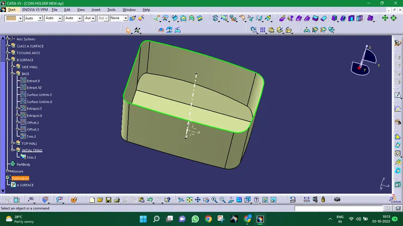
Thickeness of 2.5mm:
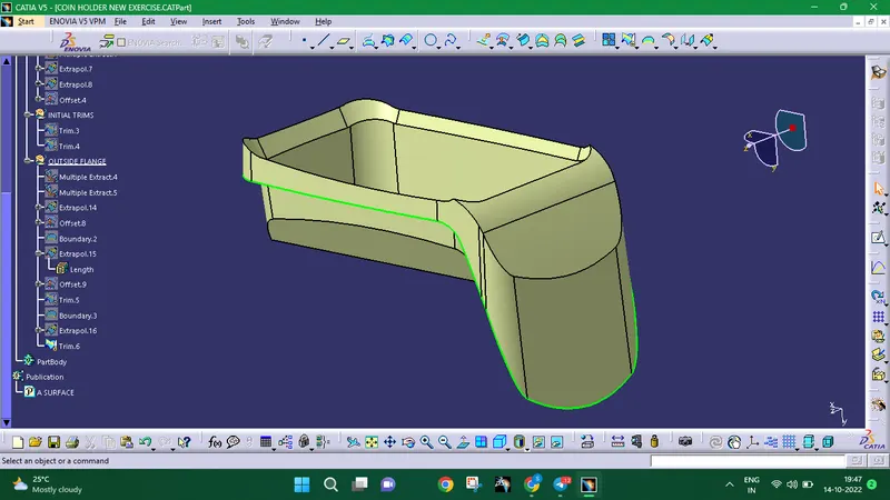
Creation of class c surface:
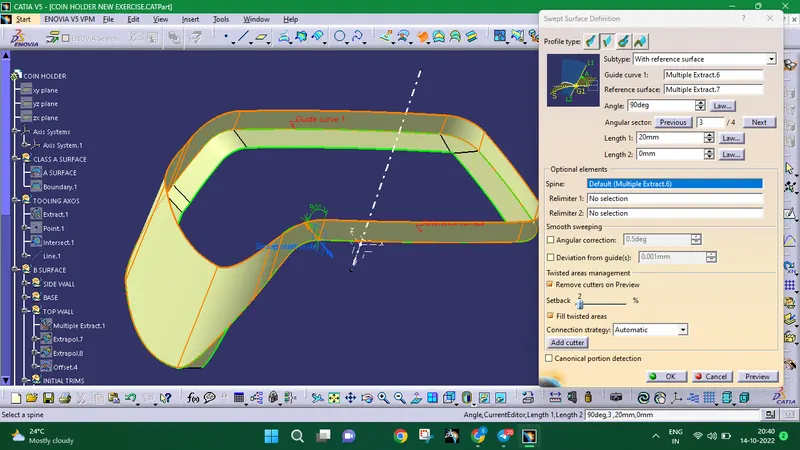
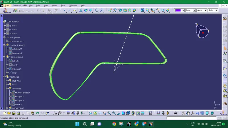
- The boundary lines of class A surface were used to produce C surface, which was then created by extracting the supporting surfaces and sweeping the boundary lines in reference to those surfaces.
- Creating boundary lines of class A surfaces or utilising numerous extrapolation commands, then confirming their continuity, is required in order to obtain the C surface first.
- Create a sweep with a 90° angle between the reference surface and the curve, giving the inner direction.
- Check the surfaces for continuity; if there is any, extrapolate and trim the surfaces collectively to get the class C surface.
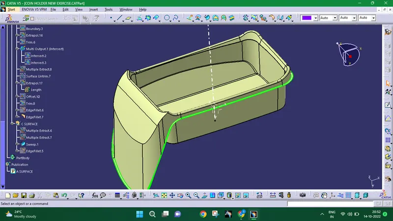
Fillets to B surface
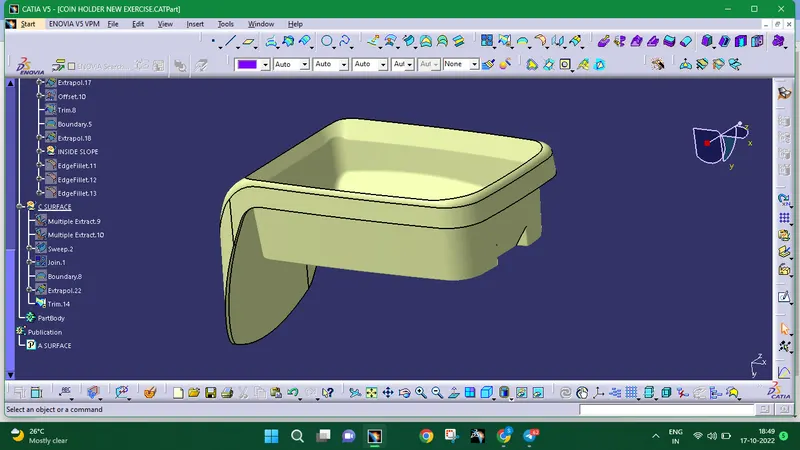
CLOSED SURFACE:
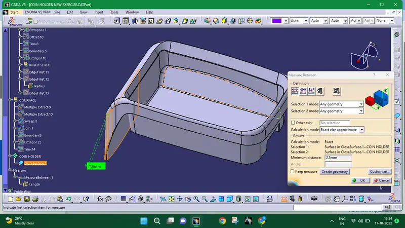
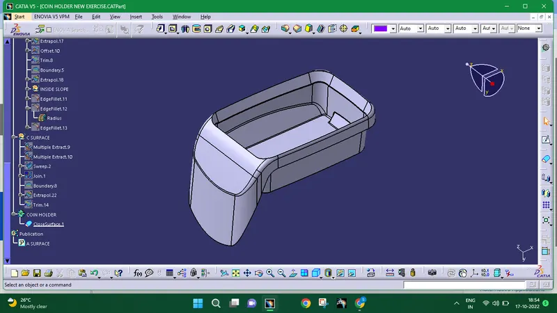
FINAL COMPONENT:
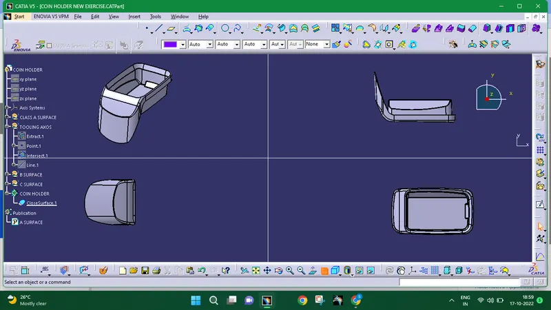
solid model with the proper color code of the draft angle in various orientations (Isometric, Front, Side, and Top View):
DRAFT ANALYSIS:
- Most components or applications require a minimum of 0.5 to 1 degree draught angle, and 3 degree draught angle is typically employed as the standard.
- Draft permits the component to escape from the mould.
- Before beginning the draught analysis, switch the material mode to customizable mode.
- Choosing the draught analysis option from the toolbar, clicking on the compass symbol, and then locating the component where you want to perform the draught analysis by removing the compass from the right side top corner of the workbench. The tooling axis and the compass's "W" should be parallel to one another.