Week 2:- BiW Fixture Basics Challenge
1. What is the process of project execution activity?
<!--[endif]-->
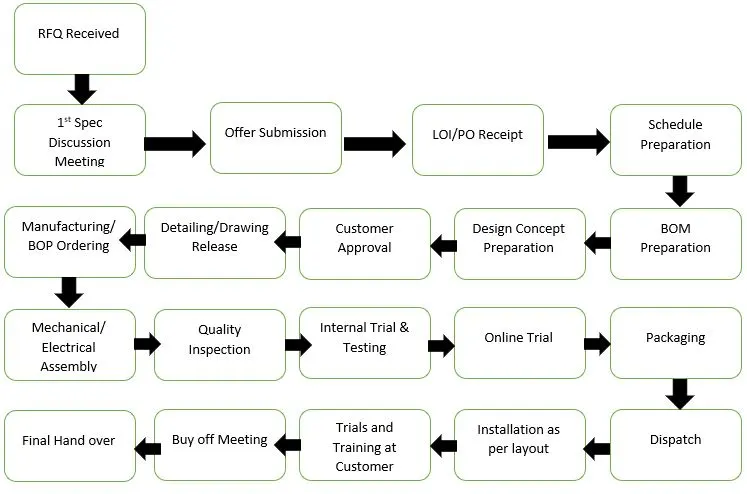
RFQ received: The first step of the project execution activity is to Request For Quotation(RFQ). Quotation is based on the requirements of the customer in the written document format which gives detailed information about the specifications and time period.
1st spec discussion meeting: Discussions will be made based on the concept they are going to adopt for manufacturing the part and if it is satisfied then they will move forward for the offer submission.
Offer submission: After the finalization, the offer is submitted to the customer end. The customer will also receive more offers from other companies. The customer will go through the offers and analyze them.
LOI/PO Receipt: A Letter of Intent (LOI) and the purchase order is a short non-binding contract that a binding agreement, such as a share purchase agreement will be made to start working with the requirement.
Schedule preparation: After receiving the PO the project schedule preparation will be done to meet the deadlines and to complete the project. All the steps in the project are taken into account like PO receipt, 1st spec design meeting, design date analysis, 3D design preparation & simulation, etc. The time required to finish the individual activity is calculated. The total time will be calculated to check whether the project can be finished in a specified time or not. If it seems to be not possible alternative plans are also to be prepared. These alternative plans come into action in project completion whenever there are deviations.
6. BOM preparation:
Bill of materials like cylinders, motors, bolts, nuts, etc., are listed and prepared.
7. Design concept preparation:
Before this step, a complete study of design data is done as per the customer's requirements.
During the design data study activities, some rough sketches are done to get the flow of the design.
It undergoes conceptualization of basic data like spot plan, cycle time, etc.,
To avoid collision of weld guns with the clamps while traveling, a spot plan is made in the initial stage.
8. Customer approval:
In this step, the customer reviews the design data and checks whether the design fulfills the requirements of the proposed design or not based on the technical offer.
If it is ok then the customer will finalize the approval and if it is not ok, several steps are to be taken to re-examine the schedule and design. After that, the result must be submitted for approval.
9. Detailing and drawing release:
Once the customer approves the project, the detailed drawings and designs are prepared at the manufacturer's end.
It is released for all the parts required with the appropriate dimensions, tolerances, quantity, specifications, etc.,
10. Manufacturing/BOP ordering:
In this stage the required components for manufacturing like motors, cylinders, sensors, grippers, etc., are ordered as per the specifications required.
11. Mechanical/ Electrical assembly:
After all the parts from the BOP ordering are received, they are subjected to quality check by the quality department concerning the specifications.
Then the mechanical and electrical parts are assembled.
12. Quality inspection:
Quality checking is again done once after the assembly is finished.
The dimensions, positional accuracy, and coordinates are checked by using a CMM machine.
Only the approved assembly is passed to the next level, rest is sent back to the assembly for re-assembly work.
13. Internal trial& testing:
The next quality check is the internal trial which is done to evaluate the operation of the fixture.
In-house testing is where the seating of the assembly/panel, clamping, and position of pins into holes are checked for a proper outcome.
14. Online trial:
It is done in automated mode by using electrical connections. The process sequence is checked as per the designed way in front of the customer for further approval.
15) Packaging: The assemblies are packed adequately in such a way that no damage occurs during transportation. Otherwise, small damage will lead to distortion of the geometry of the fixture and the functionality of the fixture. Hence proper packaging is very important.
16) Dispatching: Once the packaging is done the fixture will be dispatched to the customer's address.
17) Installation as per layout: layout is the space defined for the parts like fixtures, robots, etc., The layout is designed by considering the functionality, application, process sequence, etc. Hence installation is to be done as per the layout.
18) Trials & training at the customer: Production trials are performed at the customer's end after the proper installation. In the technical offer, we have specified the quality benchmarks, the capability of the fixture for production, etc. The trials are done to check and show the capability of the fixture to the customer. After the trials the training is given to the operator, staff & engineer for the process sequence, how the fixture works, loading & unloading of the part, etc.
19) Buy-off meeting: In this meeting, we allow the customer to ask their doubts and also, and we also provide additional information related to the project. By the end of the meeting, all the details and doubts will be cleared to satisfy the customer and help to proceed further with the product.
20) Final Handover: In this step, the product is finally handed over to the customer.
2. What are the types of joining processes?
Joining Process :
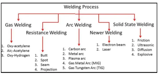
The joining process is used to combine two parts into a single component by providing support in the form of a weld or glue or with fasteners. These include different welding operations, gluing, fasteners, soldering brazing, adhesive bonding, etc.
<!--[endif]-->
Types of Joining process :
1. Mechanical Joining Process
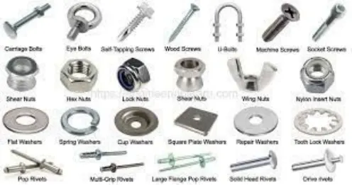
It is the process of joining the different parts with the help of the fasteners like bolts and nuts, screws, and rivets.
<!--[endif]-->
2. Metallurgical Joining Process
Some of the most important joining methods are
1. Self Piercing Rivets :
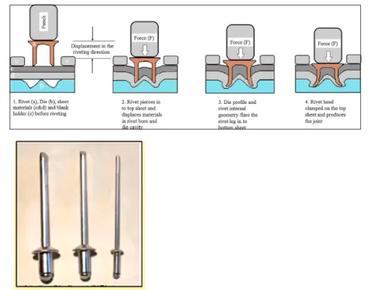
Rivets generally lock themselves with the component with the application of pressure. It does not require predrilled holes. The advantage of the rivet is that it can hold the parts together in the position and doesn't allow the components to move.
<!--[endif]-->
2. Hemming and Seaming process :
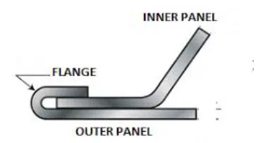
The hemming and seaming are most suited for the sheet metal joining process, in this outer sheet is bent over the inner sheet. Sheet Metal is rolled over the other with different roller sizes and orientations. Hemming it will just bend the sheet to 180 to form a U shape and there will be a 0.2mm thickness gap, whereas in seaming that gap of 0.2mm will be filled with the seam material so will glue between the surfaces.
<!--[endif]-->
3. Adhesive Bonding :
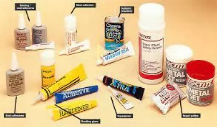
This includes glues, epoxy resins, and other plastic agents that bond together when we apply heat and pressure.
 <!--[endif]-->
4. Soldering:
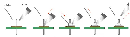
joining process used to join similar or dissimilar metals together by melting solder. Solder is a thin metal alloy which is made of tin and lead that is melted using a heating iron. The heating iron is operated in temperatures above 600 degrees Fahrenheit which then cools to create a strong electrical bond.
<!--[endif]-->
5. Brazing :
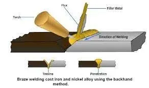
Metal-joining process in which two or more metal components are joined together by melting and flowing a filler metal into the joint. Filler material usually has a lower melting point than the adjoining metal. The brazing process does not melt the workpieces only the filler materials are melted to join.
<!--[endif]-->
3) What is Resistance Welding & its application in the automotive sector?
Resistance welding is the joining of metals by applying pressure and passage of current through the metal area to be joined. In this joining no extra material is required and it is also cost effective. Resistance welding was of different types such as spot and seam, projection, flash, and upset welding. The electrodes used in this welding are copper-based alloys. Resistance welding machines are designed and built for a wide range of automotive, aerospace, and industrial applications.
Resistance spot welding:
<!--[endif]-->
Resistance spot welding
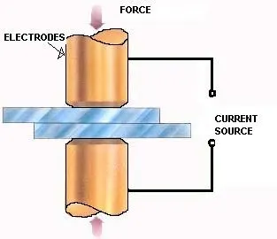
Resistance Spot Welding is done in spots. these spots are marked first at required intervals and the workpiece is placed between the electrodes and the force as well as power supply will be given which results in slight melting and joining in that spot such a welding is called resistance spot welding.
<!--[endif]-->
Resistance spot welding in the automotive industry
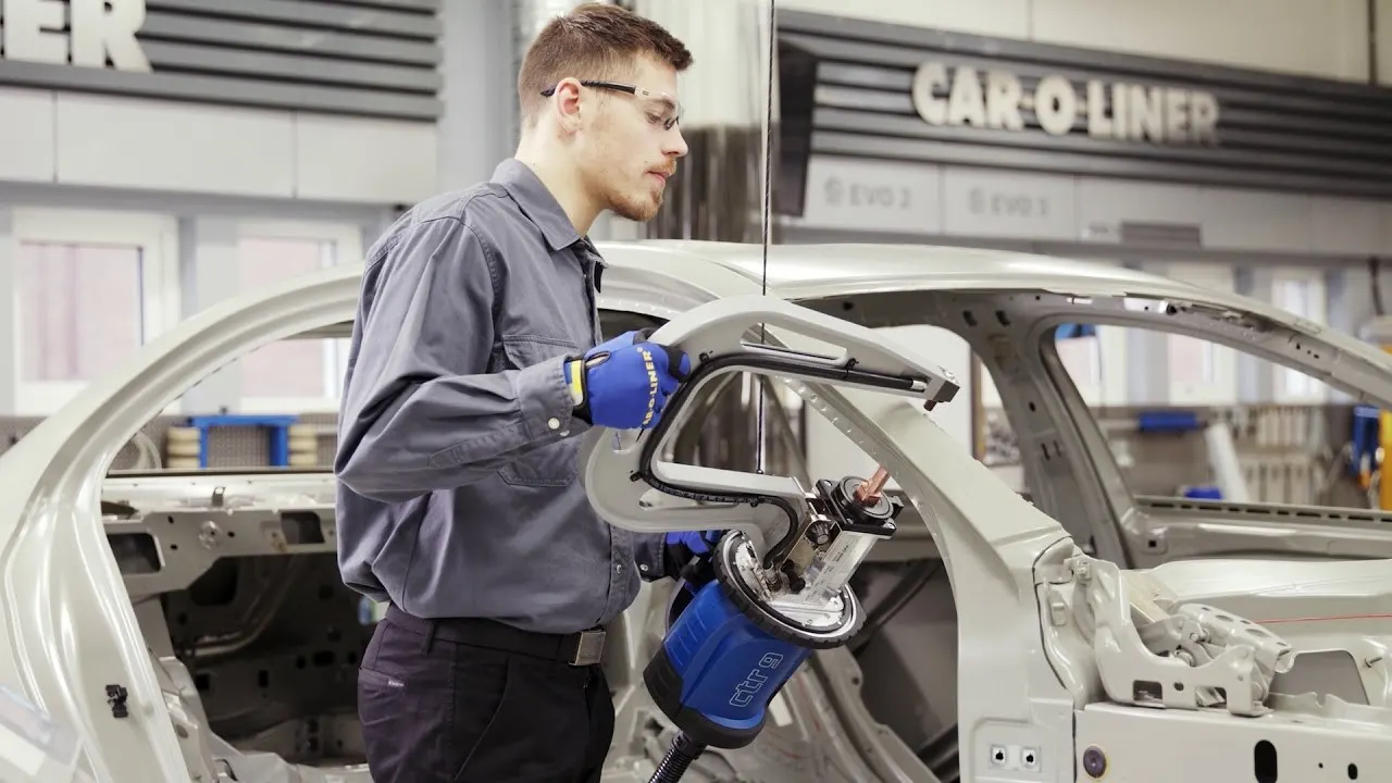
Resistance spot welding is used widely in the automobile industry as shown in the above image it is used in joining the inner and outer parts of BIW structures. Apart from this, there are a lot of applications in the automotive sector where resistance spot welding is used.
Resistance seam welding:
<!--[endif]-->
Resistance seam welding
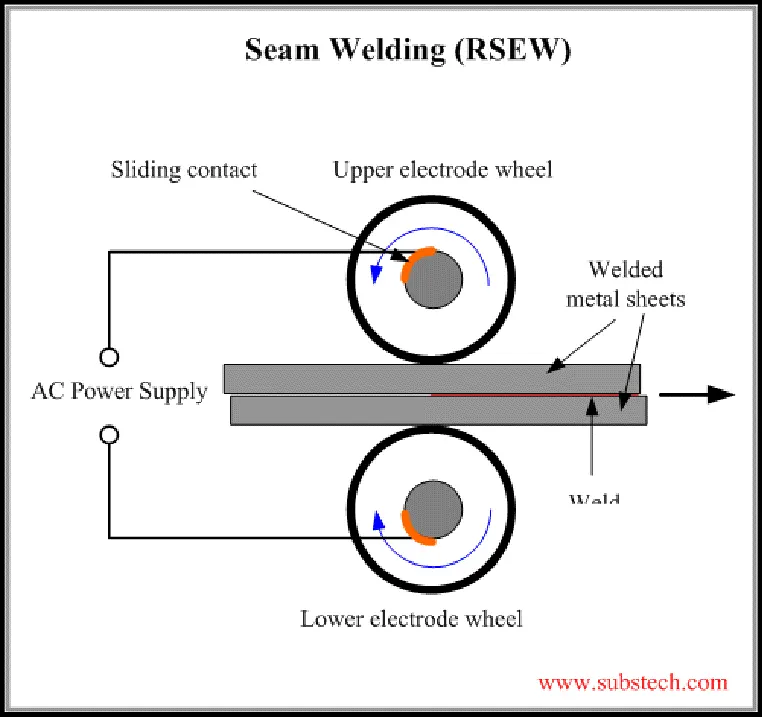
Resistance seam welding is almost similar to spot welding but instead of spots, it is performed as a whole using circular sliding electrodes. These electrodes roll along the workpiece and obtain continuous welding instead of spots. It is used for closed and no-gap parts
<!--[endif]-->
Resistance seam welding in the automotive industry
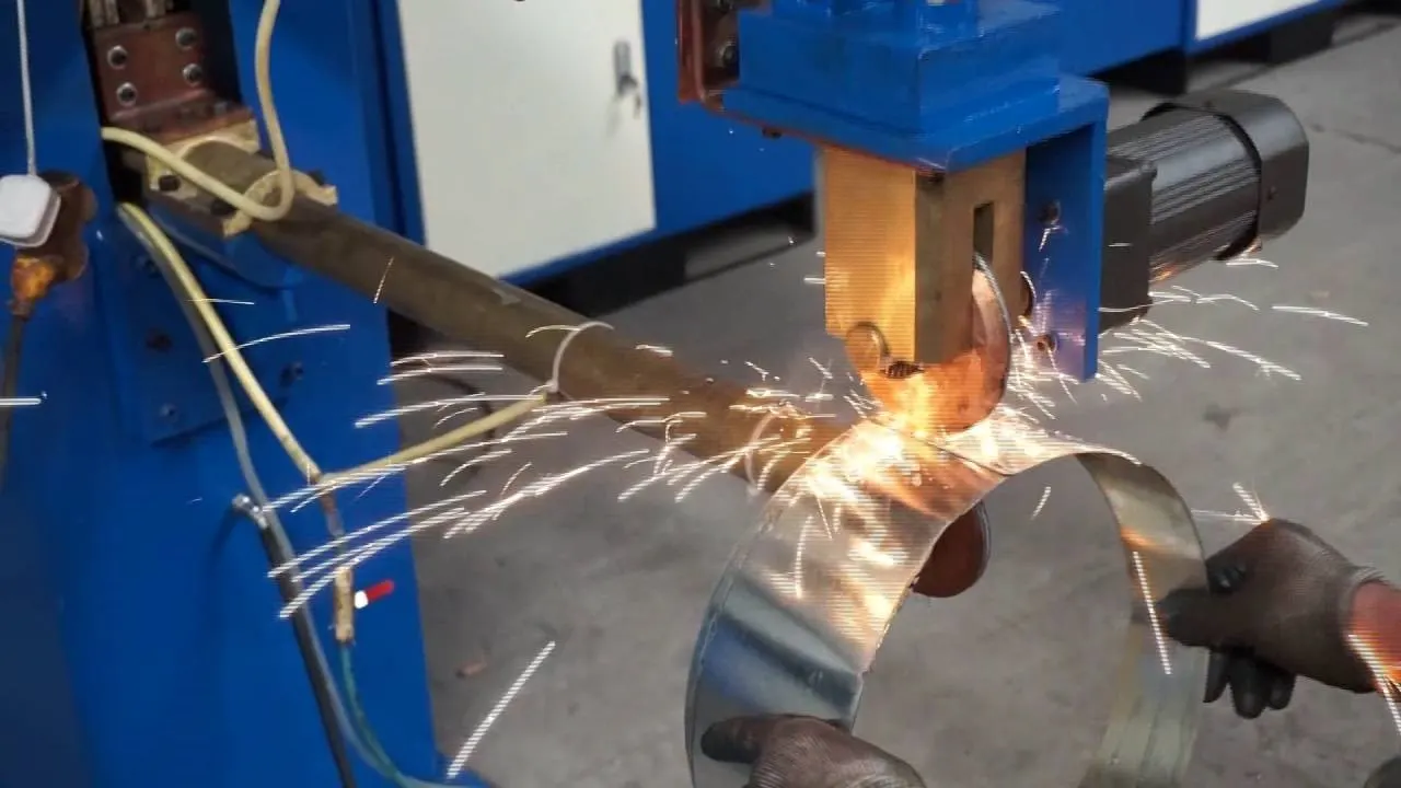
Resistance seam welding is used in the automotive sector. The parts like fuel tanks, gas tanks, and other liners or edges use resistance seam welding. It welds without any gaps or spaces. This welding perfectly seals the parts. hence wherever leakproof components are there this welding comes into play.
Resistance projection welding:
<!--[endif]-->
Resistance projection welding
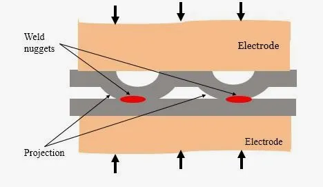
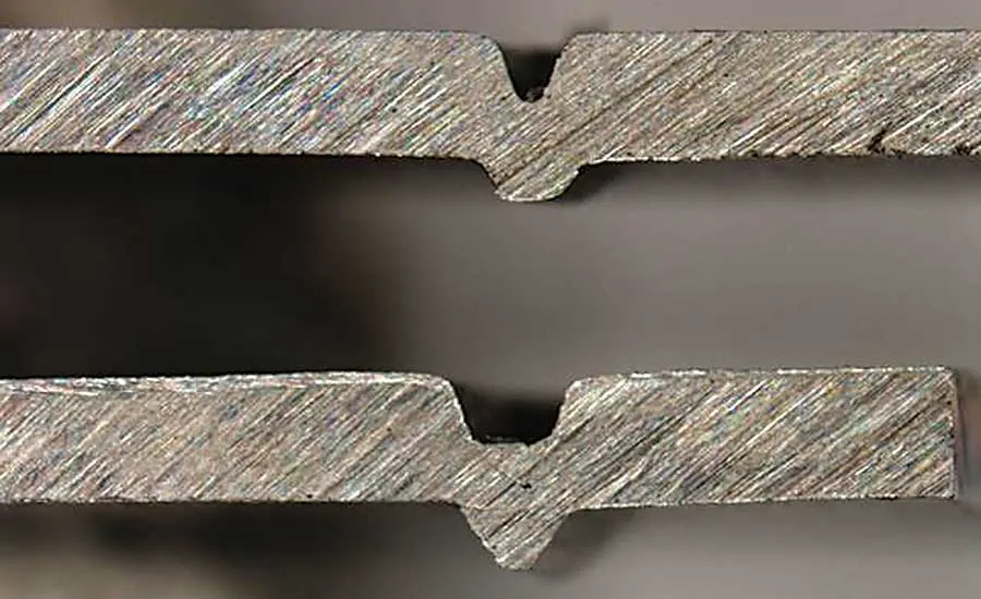
Resistance projection welding is almost similar to resistance spot welding here the work piece with projections is joined. since the only contact points between the workpieces are projections. The pressure and current flows pass through the projections and joining takes place at that region such type of resistance welding is called resistance projection welding
<!--[endif]-->
Resistance projection welding in the automotive industry
Resistance projection welding is used for indoor assembly and some special parts joining the BIW structures. this welding is used
4. What is fusion welding and what types of fusion welding are its applications in the automotive sector?
Answer:
Fusion welding
In this type of welding the metal at the joint is heated to the molten state and it is allowed to solidify.
The filler material may be needed for some kind of metal joints.
It is classified as -
Thermit welding
Arc welding
Gas welding.
1. Thermit welding:
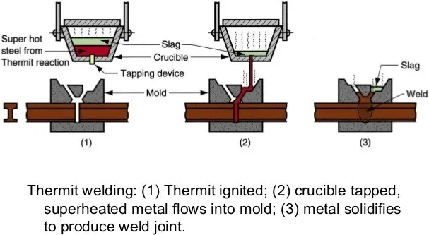
It is the welding of parts by using liquid thermit steel around the portions to be welded. Since it's a fusion welding process, neither arc is produced to heat the parts nor flames are used. For getting high temperature the exothermic reaction is used.
The welding principle is the heat of the thermit reaction used for welding in plastic states and mechanical pressure is applied for the joint.
 <!--[endif]-->
2. Arc welding:
In the arc welding process heat is developed by an electric arc. The electric arc is produced between the electrode and the workpiece.
It is a process of joining 2 metal pieces by melting their edges by an electric arc.
In arc welding, electrical energy is converted into heat energy.
The gap between the electrode and the workpiece is maintained at 3mm approx. Then current is supplied which produces the electric arc.
The workpiece and the electrode are melted and both the parts will become a single piece without applying any external pressure.
The temperature of the arc is about 5000°C to 6000°C.
A filler material is introduced during the welding which deposits along the weld bed.
The depth to which the metal is melted and deposited is called the depth of fusion. To obtain a better depth of fusion, the electrode is kept at an inclination of 70° to the vertical.
Types of arc welding:
Manual Metal Arc Welding
MIG
TIG
Submerged Arc Welding
Plasma Arc Welding
Atomic Hydrogen Arc Welding
Carbon Arc Welding
Eletroslag Welding
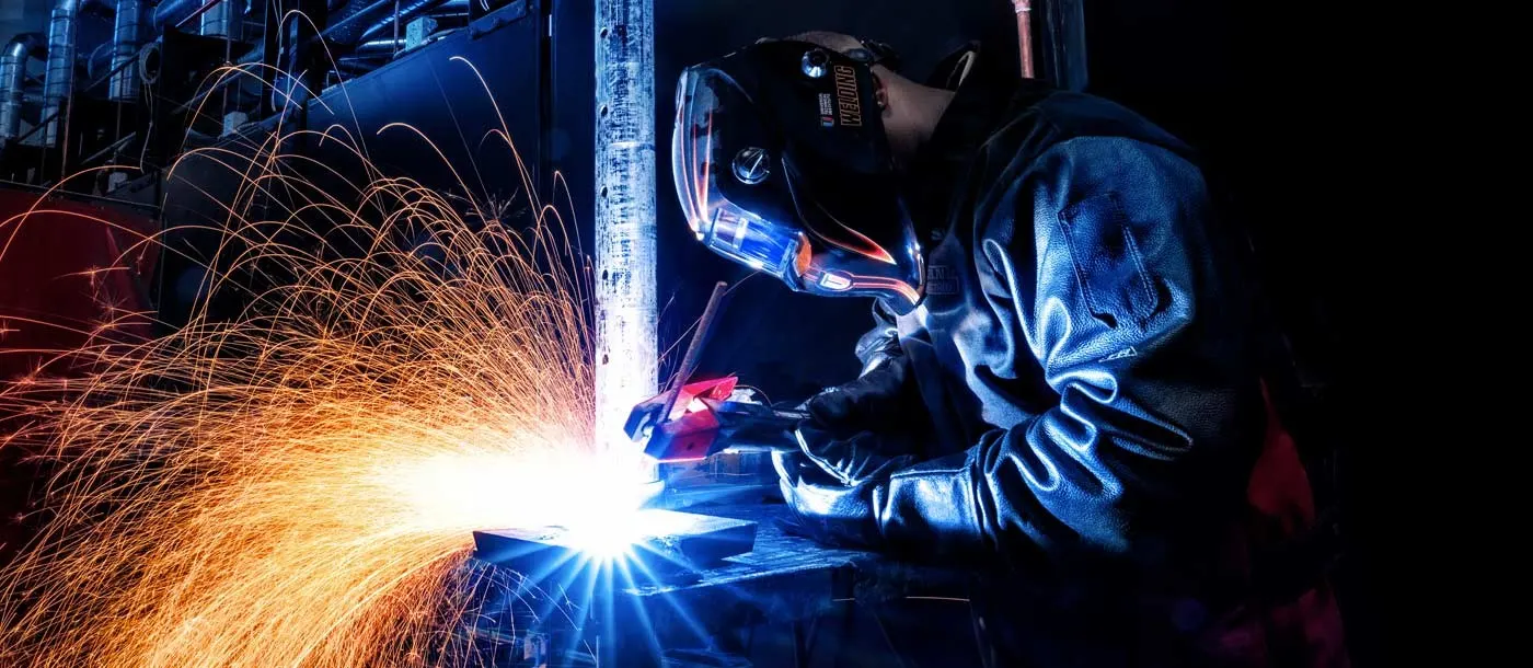
a. Manual Metal Arc Welding/ Shielded Metal Arc Welding:
 <!--[endif]-->
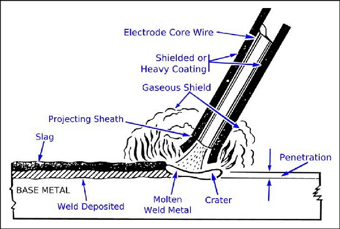
Fig shows: Shielded Metal Arc Welding (SMAW)
Manual Metal Arc Welding (MMAW/MMA) is also known as Shielded Metal Arc Welding (SMAW) and informally known as stick welding.
Stick welding is a process where the arc is struck between the metal rod (electrode flux coated) and the workpiece, both the rod and the workpiece melt to form the weld.
An electric current either AC/DC is used as an electric power supply.
That power supply is used to form an electric arc between the electrode and the workpieces.
The workpiece and electrode melt to form a molten pool which solidifies then to form the joint.
As the weld is laid, the flux coating of the electrode provides the shielding gas as a layer of slag. These protect the weld area from atmospheric contamination.
It is used in the joining of base parts of chassis and doors of automobiles.
 <!--[endif]-->
b. MIG welding:
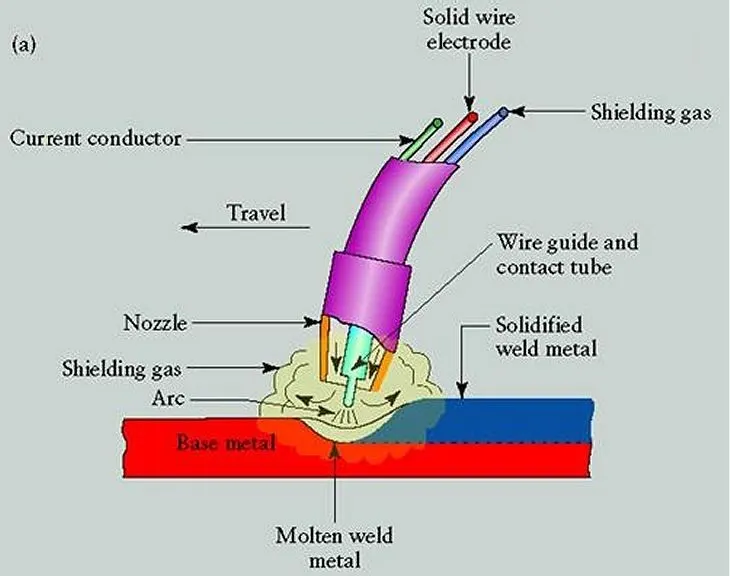
MIG welding - Metal Inert Gas welding.
It is an arc welding technique in which a consumable electrode is used to weld 2 or more workpieces.
It makes use of the following components:
Consumable electrode
Inert gas supply
Welding head
AC/DC power supply
 <!--[endif]-->
Fig shows: MIG welding
It is also known as Gas Metal Arc Welding or Metal Active Gas Welding.
The process can be semi-automatic or automatic.
A constant voltage, DC power source is mostly used with GMAW, but constant current systems as well as AC, can be used.
There are 4 primary methods of metal transfer in GMAW, namely globular, short-circuiting, spray, and pulsed spray each of which has distinct properties and corresponding advantages and limitations.
This welding is used in the joining of bone, chassis area, and engine parts in the automotive industry.
c. TIG:
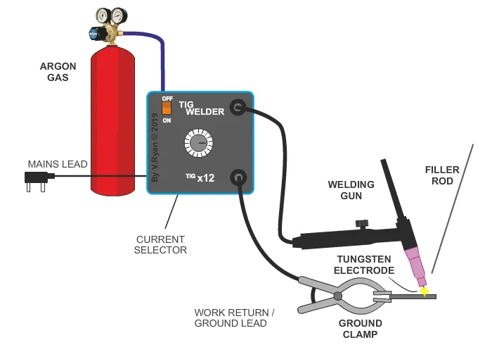
TIG - Tungsten Inert Gas Welding.
It is an arc welding technique that uses a non-consumable electrode tungsten electrode to weld 2 or more workpieces.
The following components are required to perform TIG welding. They are:
Power supply
Non-consumable tungsten electrodes
Inert gas supply
Filler rod(depends on the nature of the workpiece)
Welding head
 <!--[endif]-->
Fig shows: TIG welding
An inert shielding gas is used to protect from oxidation or other atmospheric contamination.
A constant current welding power supply produces electrical energy, which is conducted across the arc through a column of highly ionized gas and metal vapors known as plasma.
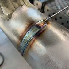
TIG welding is most commonly used to weld thin sections of stainless steel and non-ferrous metals such as aluminum BIW structures of automobiles.
 <!--[endif]-->
Fig shows: Application of TIG welding
3. Gas welding:
Gas welding is one type of welding process in which the edges of the metals to be welded are melted by using a gas flame.
NO pressure is applied during welding except pressure gas welding.
The flame is produced at the tip of the welding torch.
The gases commonly used are acetylene, hydrogen, propane, and butane.
It is used to weld metal parts with thicknesses in the range of 2mm to 50mm.
3 types of welding processes are employed in industries,
Oxy-acetylene welding
Oxy-hydrogen welding
Air-acetylene welding
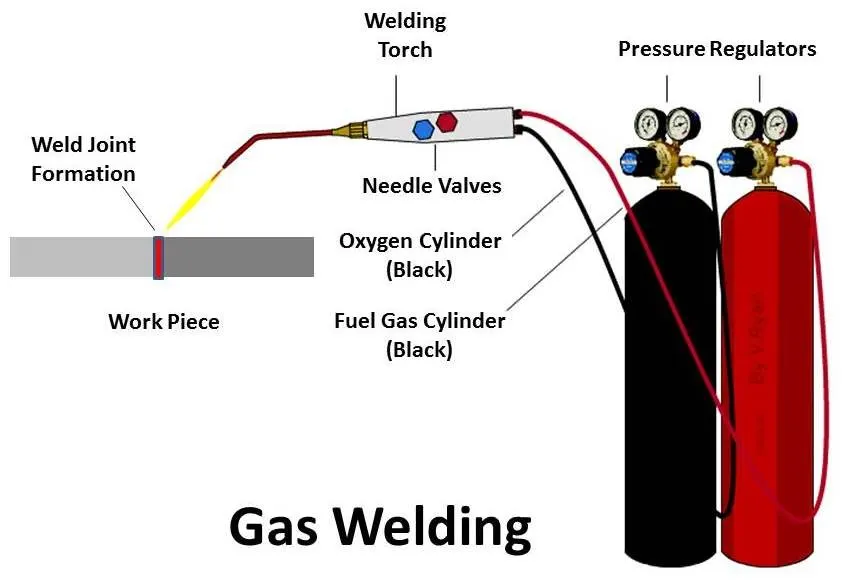 <!--[endif]-->
Fig shows: Gas Welding setup
The most commonly used welding is the Oxyacetylene welding.
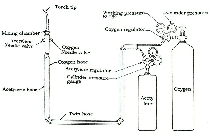
Oxyacetylene welding- In this welding, the heat is obtained by burning a mixture of oxygen and combustible gases. The gases are mixed in the required proportion in a welding torch which provides the control of the welding flame.
The flame only will melt the metal and a filler rod is used to fill the gap.
Flux is used to prevent oxidation and to remove impurities.
The temperature in the hottest region is about 3200°C.
The cost of acetylene is low. The gases O2, C2&H2 can be stored at high pressure in separate tanks. But the acetylene is very harmful if it is not handled carefully.
There are two systems High pressure system and low pressure system.
<!--[endif]-->
5. What is the 3-2-1 principle?
Answer:
3-2-1 Principle
During the metal working process, it is very important to locate the workpiece to be worked concerning the fixtures.
The accuracy with which a part is machined is quite dependent on the accuracy with which it is positioned in the fixture.
Any variation in part location on the fixture adds to the dimensional tolerance that must be assigned to the finished parts.
This is true because improper support or clamping can temporarily or permanently deform the part.
The method of supporting and securing the part in the fixture affects not only dimensional tolerances but also surface finishes.
Techniques for supporting and clamping must be considered together with the method of locating to assure repeatability from part to part.
The basic principle of fixture is to restrict all degrees of freedom in the desired location and orientation.
Locating a part to be machined is a three-step process:
1. Supporting
2. Locating (positioning)
3. Holding (clamping)
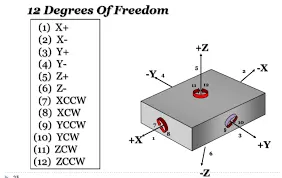
Fig shows: Degrees of freedom for a body in space
The 3-2-1 principle is the fundamental principle of all fixture design. While designing a fixture a major part of time is spent in locating the workpiece in the fixture.
Generally, a free body has 12 DOF(degrees of freedom):
6 Translational DOF
6 Rotational DOF
Translational DOF includes:
+X, -X, +Y, -Y, +Z,-Z
Rotational DOF includes:
Clockwise around the X axis (XCW/CROT-X)
Counter or anticlockwise around X axis (XCCW/ACROT-X)
Clockwise around Y axis (YCW/ CROT-Y)
Counterclockwise/anti-clockwise around the Y axis (YCCW/ACROT- Y)
Clockwise around Z axis (ZCW/CROT-Z)
Counterclockwise around Z axis (ZCCW/ACROT-Z)
For proper fixing of parts, one should restrict all 12 DOF of the workpiece. This is achieved by providing 6 locating points, 3 pins in the base plane, 2 pins in the vertical plane, and 1 pin in a plane that is perpendicular to the first 2 planes.
Without the 3-2-1 principle, it’s very difficult for the BIW product engineer, BIW process engineer, or BIW fixture design engineers to have the same clamping and location scheme.
Any geometry is fixed or held in position with the 3-2-1 principle. To restrict its transverse motion in X, Y, and Z directions and rotational movement in X, Y, and Z directions object will be held in position with the 3-2-1 principle.
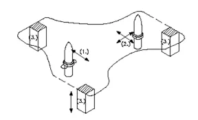
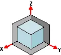
For example: Consider a solid cube lying on the XY Plane and Z is height.
 <!--[endif]-->
3 Points in Z direction define the plane and restrict its movement along Z and rotation along X and Y.
2 Points in X direction restrict its movement in X and rotation along Z.
1 Point in Y restricts its movement in Y.
This fundamental is used during the automotive body component design and welding tool design for its manufacturing.
Locating Process:
 <!--[endif]-->
First plane-
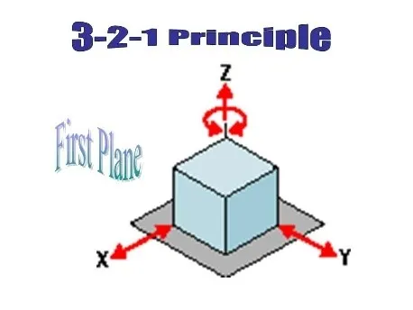
This is the "3" in 3-2-1. So, three specific points are used to define the first plane.
Fewer than three points cannot define a plane, and in the real world dimensional tolerances mean that four or more points will not be coplanar. A real-world, less than ideally, perfect part placed on four or more reference points will rest on only three of the points due to its less-than-perfect surface.
Different parts may rest on different combinations of three points, resulting in variation between finished parts. A stool can be used to illustrate this concept.
A two-legged stool would certainly be unstable. A three-legged stool sits rock-solid. A four-legged stool is often found to rock. In the illustration, a three-dimensional part, represented by a cube, is placed on a datum plane defined by three support points.
<!--[endif]-->
TIPS
Use the largest surface of the part for the first ("primary") reference plane.
Position the three support points as far apart as possible.
If more than three support points are required to prevent deflection, make the additional points adjustable.
Second plane -
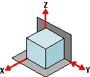
A second plane, if it is perpendicular to the first, can be defined by two points, the "2" in 3-2-1.
The part is now constrained to one degree of freedom: movement along the Y-axis. (The part cannot move along the X or Z axes because it is held against the planes by clamping force.)
TIPS
Use the largest surface of the part for the first ("primary") reference plane.
Position the three support points as far apart as possible.
If more than three support points are required to prevent deflection, make the additional points adjustable.
Third plane -
A third plane, if it is perpendicular to both of the first two planes, can be defined by one point, the "1" in 3-2-1. The part is now entirely constrained.
It cannot move along or rotate about the X, Y, or Z axes. (Remember that the part is held against each of the three planes by clamping force.)
<!--[endif]-->
TIPS - If more than one support point is required to prevent deflection, make the additional points adjustable.
6) Define the Body coordinate system.
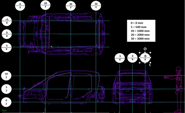
The body coordinate system is also called a car line or body line. The coordinate system is a reference system Consisting of a set of points, Lines & surfaces used to define the position of the point in space either in 2 or 3 dimensions
Maintaining X, Y & Z coordinates in the fixture is a very important factor. We should try that the coordinates of locating and clamping points should not be in three decimals (e.g. X=100.124, Y=245.127, Z=450.458). They should be in the whole nos. or max up to 1 decimal. Once these co-ordinates are maintained automatically the BIW base structure is maintained.
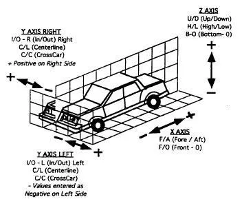
All vehicle product drawings are identified numerically relative to three vehicle planes Description is shown below.
(X) It is in width of BIW – 0X is the Body Center Line
(Y) It is in the length of BIW – 0Y and is Near Front Bumper
(Z) It is in the length of BIW – 0Z and is about the center of the wheel
 <!--[endif]-->
Typical body coordinate system in BIW and car body
7. Elaborate Body Plane System & its essentials.
Answer:
BODY PLANE SYSTEM
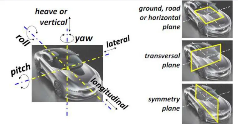
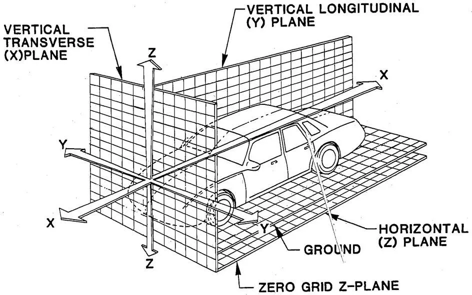
Body planes are reference planes in an automotive car. These planes are used to define the GD&T of all parts in an automotive domain.
Body planes are 3 mutually perpendicular imaginary planes.
The measurement from body plane to parts is called body plane dimensions.
The planes are generally considered to be present in the driver position or sometimes at the engine location or the front end of the car depending on the customer.
 <!--[endif]-->
<!--[endif]-->
The measurement from the body planes to the parts are called the body line dimensions.
X = Longitudinal direction[(Fore and After- F/A) or (Front O Line- FOL)]
Y = Transverse direction[(Cross car- C/C) or (Centre O Line- COL)]
Z = Vertical direction[(Up and Down- U/D) or (Bottom O Line- BOL)
<!--[endif]-->
Fig shows the typical body plane of a car
Body line dimensions are essential for the following reasons:
It defines the exact position of each product in the vehicle concerning a fixed origin.
It ensures flawless design for assembly.
While designing lines, all the designs are carried out relative to the bodylines viz. fixtures, turntables, etc.,
It assists in the easy location of different parts in the vehicle.
It aims to create a standardized system.
It assists in quality checks.