Advanced Sheet Metal Design Using NX Cad Challenge_7_ Metal bracket-II
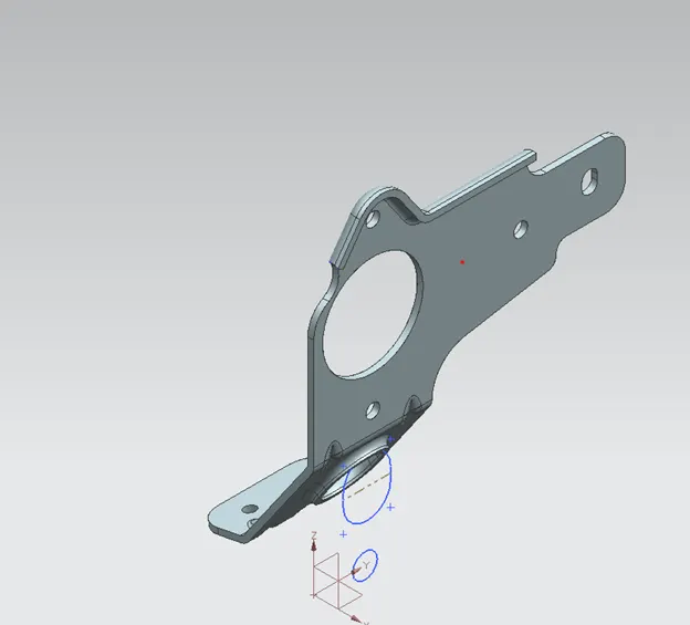
NX_Bracket-II_stp_Abhishek-Sonawale
- Objective:
In the NX sheet metal modeling, we use various commands and get final output of Model
- Introduction:
In this design of Bracket in NX sheet metal. We will understand the how use the bead and Hole command in NX sheet metal.
- Design Methodology:
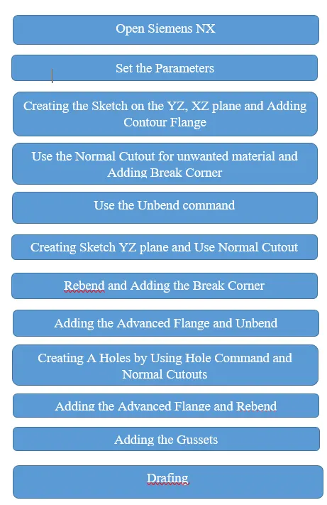
` 
- Descriptions:
- Open Siemens NX
First open Siemens NX and select the New file ( or Use Ctrl+N)
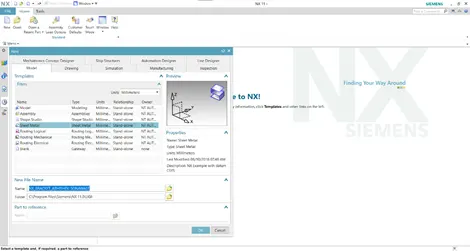
In the New file select the sheet metal and Name it as we want.
- Set the Parameter:
In NX sheet metal, to set the default design parameter value, Menu-Preferences-Sheet metal option is used
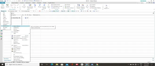
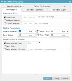
In the sheet metal preferences, all the global parameters are set to 3mm, while the neutral factor (K-factor) value is kept at 0.33 and click on OK button
- Use the contour flange:
In creating a base, firstly select Contour Flange command and click on sketch mode in dialog box. After selecting sketch mode, it asks for selecting Datum Plane. Then select XZ plane
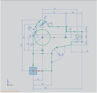
After that Draw this Sketch on Plane
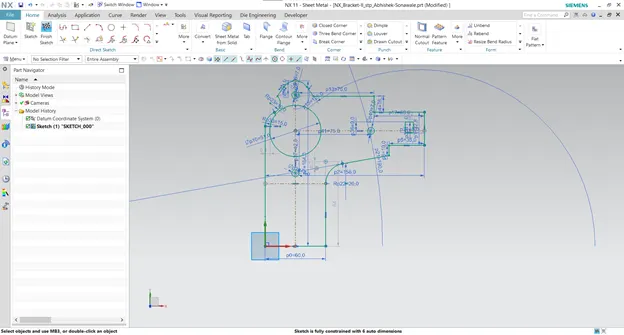
Exit the sketch mode then create contour. But in contour Flange this isn’t sketch we use. In the contour flange we create the Sketch on the XZ plane.
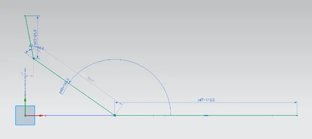
After creating the sketch on XZ plane and exit the sketch mode. In contour flange width will be 158mm.
- Use the Normal Cutout for unwanted material and Adding Break Corner:
First select the Normal Cutout in the ribbon. Then click on the sketch mode, select the YZ and Create Sheet Metal shape as per Sketch on YZ.
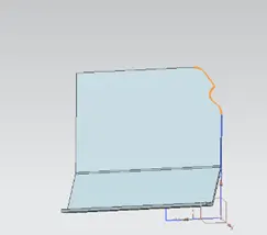
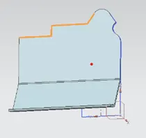
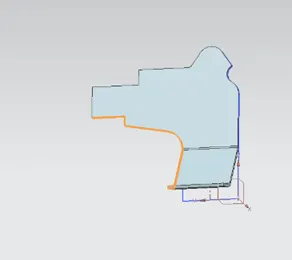
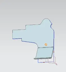
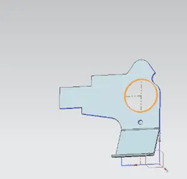
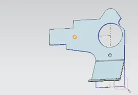
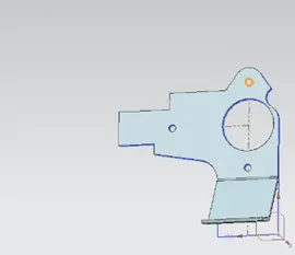
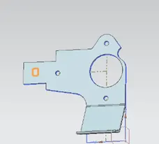
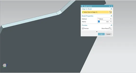
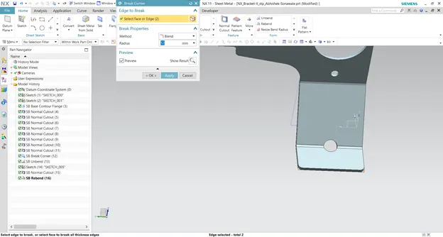
After that add the Normal cutouts, Add the Break corner 4.5mm on upper Edge in Blead
- Use the Unbend command:
After that select the Unbend command. In the Unbend Dialog box select the Face and Bend. Click on ok Button.
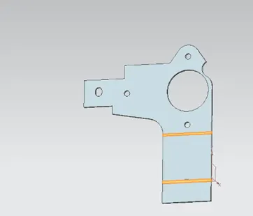
- Creating Sketch YZ plane and Use Normal Cutout:
Select sketch mode, set the YZ plane and click on OK button.
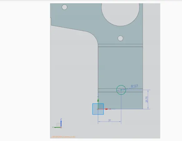
Draw this sketch on plane and Exit the sketch mode. Use Normal cutout command and subtract the material.
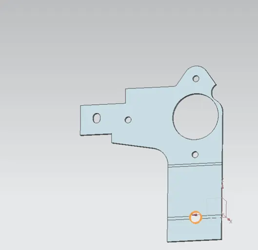
- : Rebend and Adding the Break Corner:
After adding the Normal Cutout Feature, use the Rebend command for Previous shape of metal sheet with Added feature.
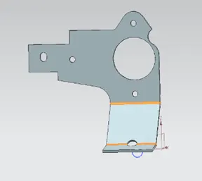
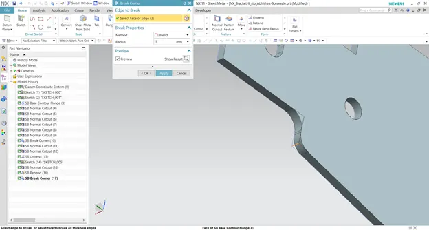
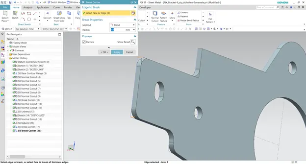
Adding the Blead at sharp Edge by using Break Corner command.
- Adding the Advanced Flange and Unbend:
Advanced Flange is used to create flange with various shape in sheet metal. Selecting the Advanced Flange, select the upper edge and create the Advanced flange with 5mm Length and 3mm Bend Radius.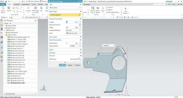
After that select the Unbend command. In the Unbend Dialog box select the Face and Bend. Click on ok Button.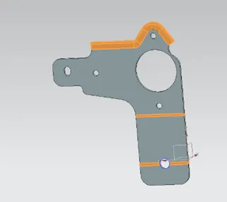
- Creating A Holes by Using Hole Command and Normal Cutouts:
Find the Hole command and select it. In the Hole dialog box there Specify Point option and go to the sketch mode. In sketch mode select the YZ plane.
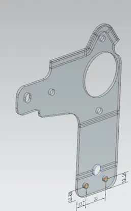
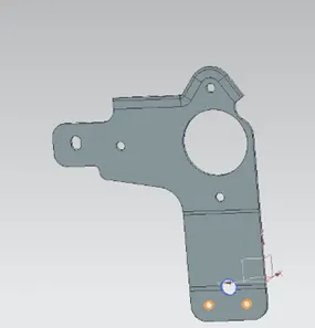
Exit the sketch mode. In Hole dialog box, Set the type of Form in Simple. After that Diameter is 6mm and Depth limit will be “Through Body”. Click on OK button and see the holes in the metal sheet.
Select the sketch mode and Draw sketch on the YZ plane. After that subtract the material by using Normal Cutout command. 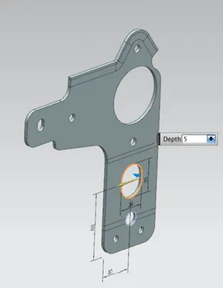
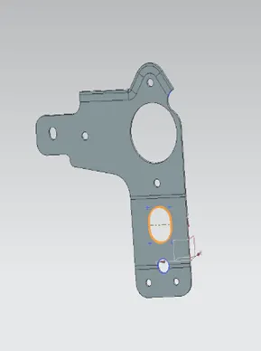
In the Normal Cutout Depth will be 5mm.
- Adding the Advanced Flange and Rebend:
After that adding Normal Cutout, we will Add Advanced Flange.
Firstly, select the Advanced Flange. Set the value of Length in 4mm and Bend Radius in 3mm.
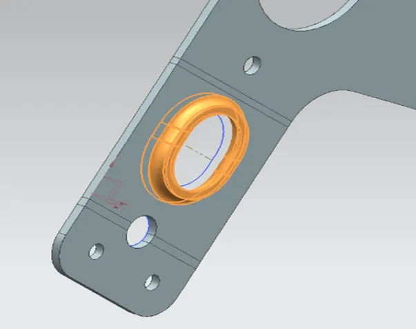
After that Rebend the metal sheet in previous shape with adding Features.
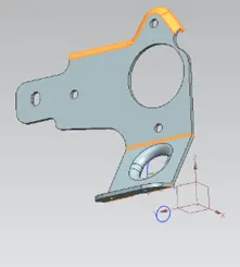
- Adding The Gussets:
Gussets is used for strengthening the metal sheet. Adding the Gusset of 5mm in metal sheet by using Gusset command.
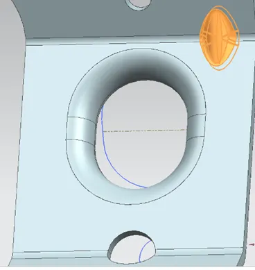
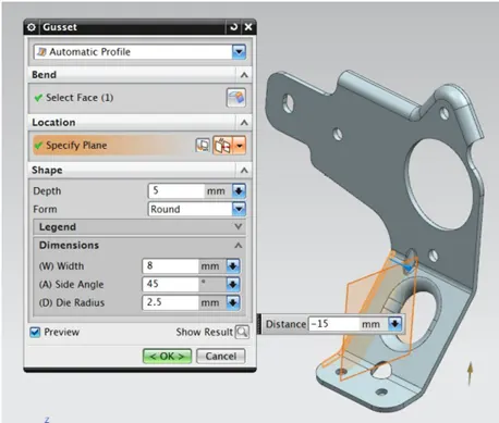
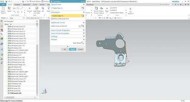
Redo for another three Gusset and Create Flat pattern.
- Drafting:
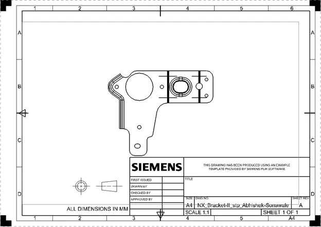
For Drafting select the Drafting Option in Application.
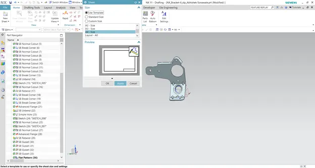
In the sheet dialog box, set the size of drawing sheet in A4 size.
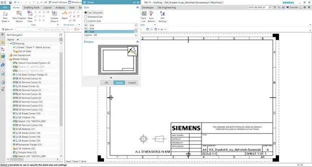
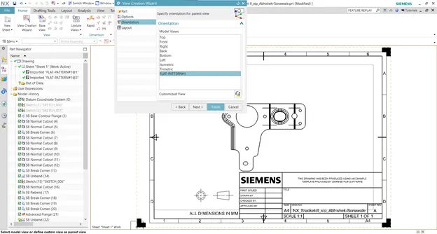
After the creating sheet select the View Creation Wizard. In the View Creation Wizard, click on the orientation and select the flat pattern.
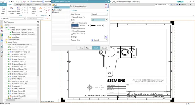
Set the scale 1:2 in the option.
We will get drawing after the clicking OK.
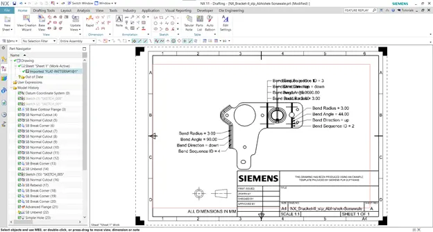
Delete the all text added in the sheet.
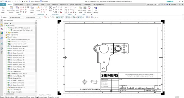
- Views
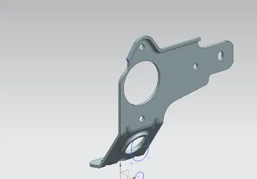
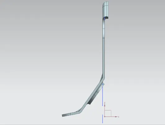
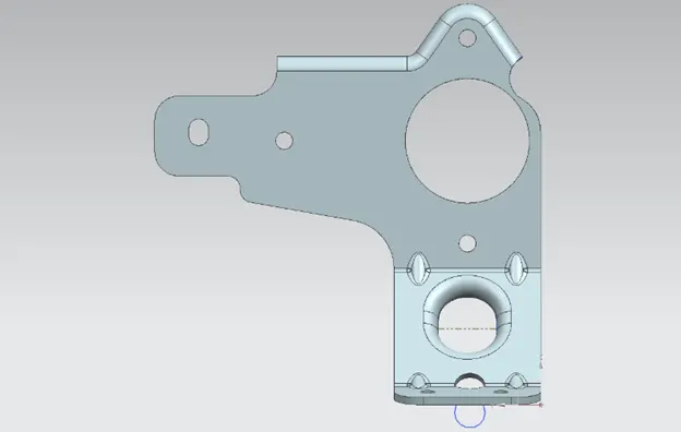
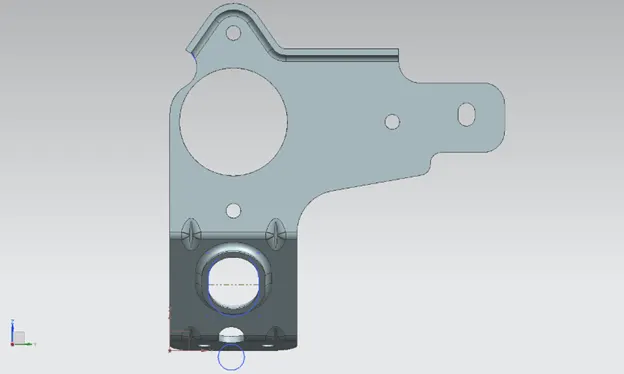
- Drawing sheet
- Conclusion:
All the various commands. We get the Final Model and the Drawing Sheet.