Advanced Sheet Metal Design Using NX Cad Challenge_1_Casing Design
NX_Casing_Abhishek Sonawale
Objective
Create model with various tool and commands with metal sheets. In this model we consider a that tool, which used in industry.
- INTRODUCTION:
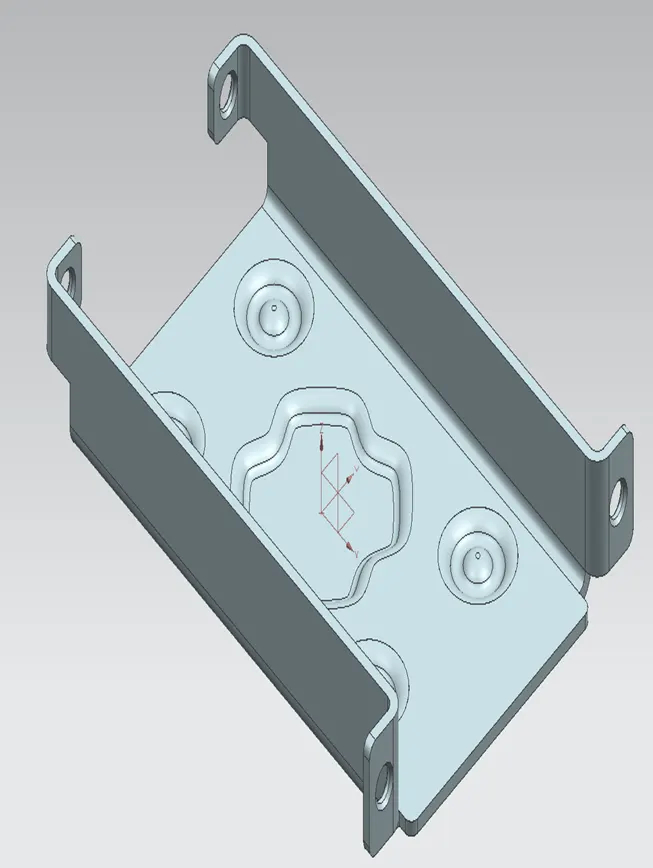
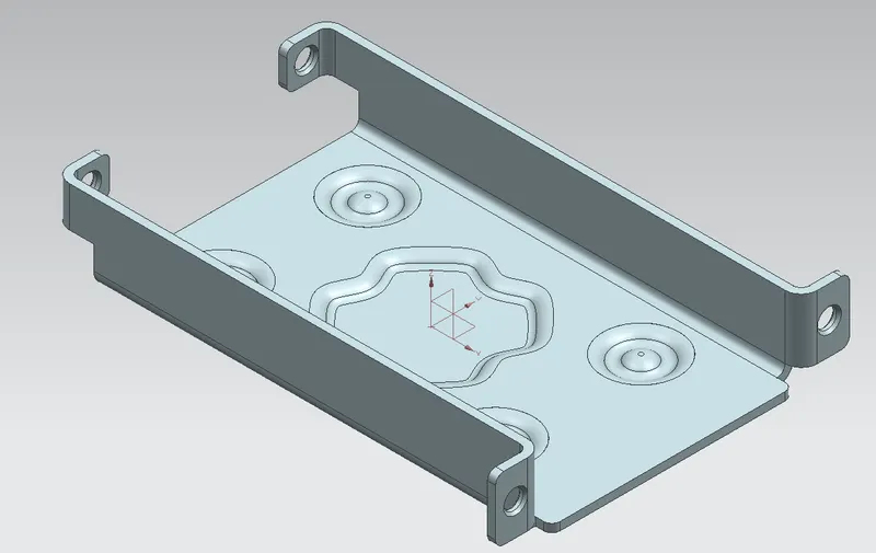
This is Sheet Metal Design create in Siemens NX 11.0. In this design,various tools are used to design this sheet metal like Tab, Flange, Dimple, Sketch and other commands.
In NX Sheet Metal is most command is friendly with other software. Casing Design is model of sheet metal.
- Design Methodology
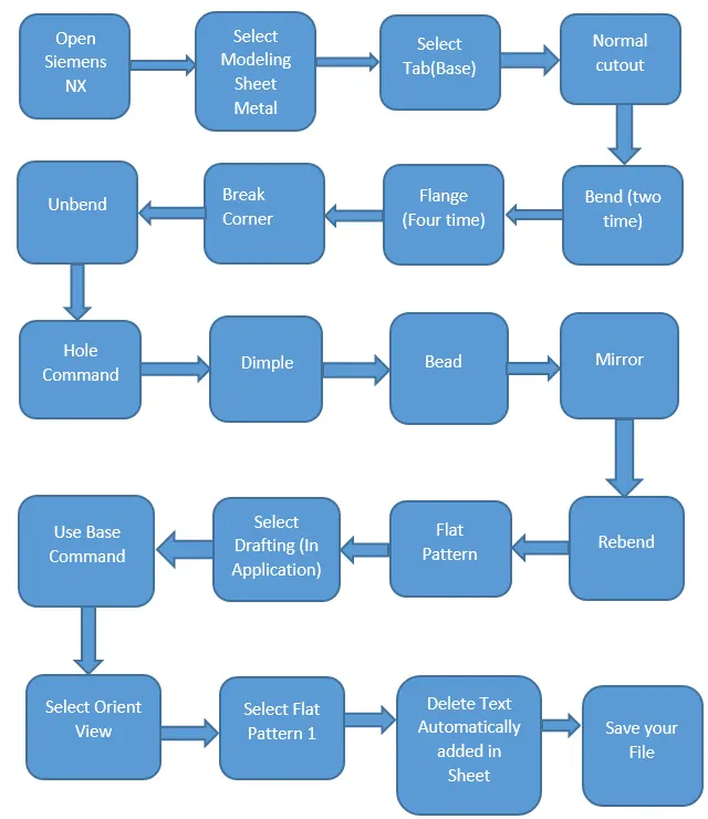
- Firstly, open Siemens NX, Select New File (Ctrl + N) then select Modeling Sheet Metal.
- In below just rename it (NX_Casing-Designing_your-name) and click on ok button.
- In NX sheet metal Designing, click on Menu Then preferences, sheet metal and in preferences dialog box, change all Global parameter value in 1mm.
- Select Tab command in Ribbon and select XY plane and draw a rectangle centered at the origin with an X-length of 60mm and a Y-width of 50mm.
- Exit the sketch mode. Click on ok button then we got 1mm thicken Rectangle.
- Click on normal cutout and select sketch mode. In that sketch, draw a rectangle symmetric with respect to the X-axis which is coincident with the left edge of the rectangular metal sheet. The rectangle is 5mm wide and 40mm long.
- Exit the sketch mode and select the direction for making a rectangle hole in the metal sheet.
- Select bend command and click on icon. Go to sketch mode and draw the line in consisting in two symmetric horizontal line with respect to the X-axis. The upper line is located at 10mm form the upper left corner of the metal sheet.
- Exit the sketch mode. in the bend Dialog box, select one line as bend line and use an angle of 90 degrees. Click ok and see the result of bend. Redo the same procedure for other symmetric line.
- Adding Flange of 5mm and 90 degrees on end of bended area. Select flange command and click on edge of metal sheet. In dialog box put all value and see the result. Again adding flange, Apply the same flange to the corresponding symmetric edge of metal sheet.
- Redo for another bend face area.
- In sheet metal there are sharp edge so adding a chamfer and round it will harmless. Select break corner command and click on sharp edges (there 10edges,6 on right side of bend face and 4 on left side of bend face)
- Select blend method with a radius of 1mm. Apply the break corner to the edges.
- Click on unbend command. in unbend dialog box select horizontal face of metal sheet. Select as bend face one of its adjacent face. Redo as many similar operations as necessary in order to obtain flat sheet metal
- Find hole command in ribbon and select it. In hole wizard dialog box there pointing option in position, click on their icon and select p plane to draw a point. But in sketch mode firstly, Draw lines for positioning point. In lower left part of metal sheet draw a line which extremities are located on the middle.
- Draw a point in the middle of line (line which extremities are located on the middle). Redo for opposite side of left part of metal sheet.
- Finally, from that point create a symmetric point with respect to the X-axis of the Datum co-ordinate system. Similarly, create two other symmetric points (with respect to the X-axis of the datum co-ordinate system) in the upper part of metal sheet. The point will have located at middle of a line (line which extremities are located on the middle). Redo for opposite side of part of metal sheet.
- There will be Four point got on metal sheet and Exit the sketch mode. In hole dialog box, use screw clearance hole as type, with a M2 Screw Size and a H13 Fit. Set the depth limit option to through body. Create four holes centered on the four previously defined points.
- For dimple firstly, Draw the sketch. Select the sketch mode and click on XY-plane for references. Draw two rectangles is perpendicular each other. Rectangle is 20mm wide and 10mm long (the sketch is centered at the origin).
- Use the trim to delete unwanted lines in the drawing. Finally, we got closed loop sketch for dimple.
- Click on the studio spline button. In the studio spline dialog box, set the type field to by poles. Check the closed option.
- Select one by one all the 16 points of the sketch in a clockwise fashion. Click OK to validate the creation of the new spline curve.
- Click on the Move Curve button. In the move curve dialog box, select the spline curve you just drawn. Set the motion option to the transform field to angle. Specify the origin as axis point and enter the angle of 45degrees and click on ok button.
- Exit the sketch mode and find the dimple command.
- Click on dimple command icon and select the curve (sketch). In dimple dialog box, set the depth option to 1mm and side walls to material inside. Expand the dialog box, in setting Rounding click on box round dimple edges.
- Change the value of punch radius and die radius in 1mm. Click on round section corners and change value of corner radius in 1mm. Click on OK button for creation of dimple.
- For bead, select Bead command in ribbon. In bead dialog box there sketch option (select it). Select the XY-plane and select circle shape in sketch mode.
- Draw a circle of 5mm located at 8mm right side of left edge of horizontal metal sheet and 8mm below of upper end of normal cutout rectangular. Exit the sketch mode.
- In Bead dialog box set value of depth and radius in 1mm and Expand the dialog box. In Rounding setting, click on box of rounding bead edges and set value of die radius in 1mm. Click the OK button and see the Bead on metal sheet.
- Click in more option in ribbon then select Mirror Feature. In Mirror Feature, select the bead and its corresponding sketch as mirror and select the YZ plane as the mirror plane and click on Apply to see the result.
- Then select the two beads with their corresponding sketch. Redo a feature mirror by choosing this time the XZ-plane.
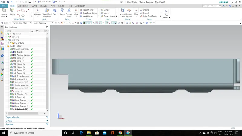
- Rebend the metal sheet with help of Rebend command. In rebend command, select the horizontal face (which is used in unbend command) and select all bends. Click on OK button and see the metal sheet in previous shape (before unbend) with added features.
- Use flat pattern command to Falt pattern view in NX.
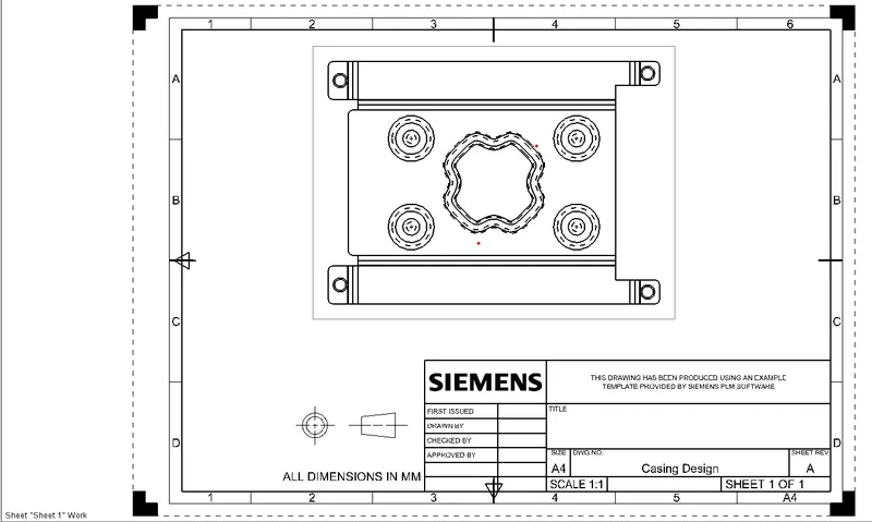
- Select Drafting mode in Applicaton and click base command. In the dialog, click orient view and select FLAT PATTERN 1.
- Delete text automactically added in the Sheet and save you file in the PC.
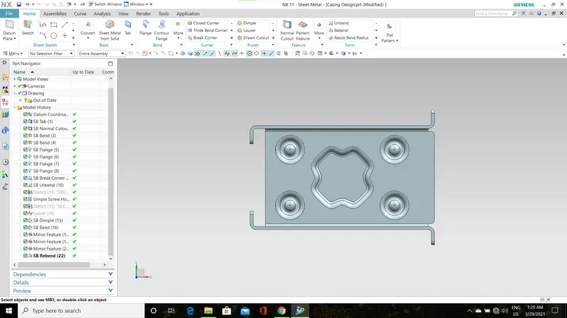
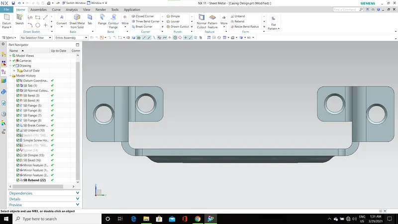
Conclusion:
In the sheet metal, various tool is used to create perticular model like Tab Bend and other commands. Finally we get the Perticular Model