Roof challenge
NX CAR ROOF DESIGN AND CALCULATION
- Objective:
The objective of this project is to design a car roof with essential flanges and reinforcements like ditch area, front roof rail, bow roofs, central roof rail, and rear roof rail for the given styling surface
Perform the calculations for the heat distortion and snow load criteria to determine whether the bow roofs are at the correct positions.
Finding a moment of inertia and section modulus for Bow roof rails.
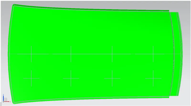
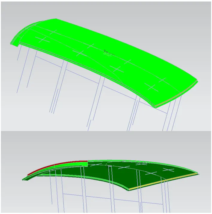
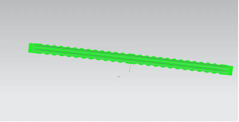
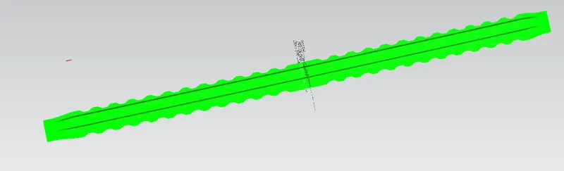
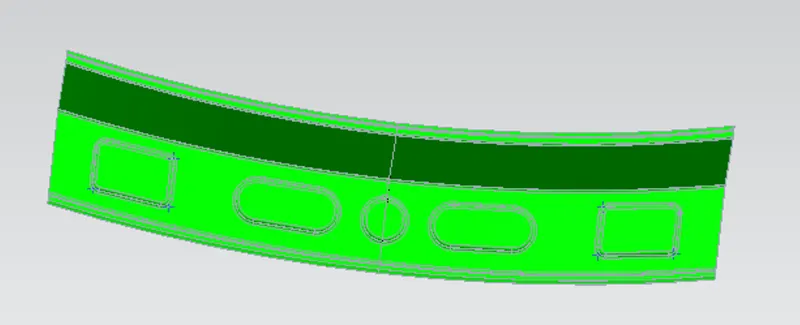
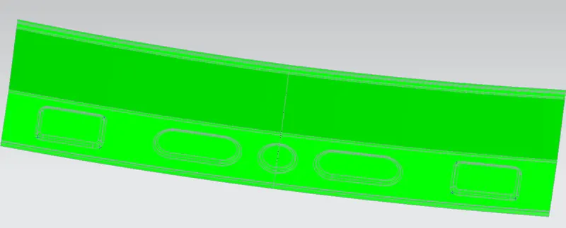
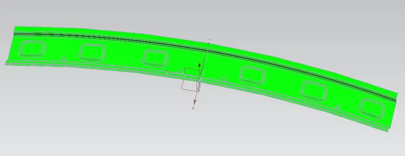
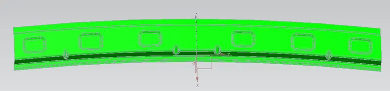
Perform the draft analysis for each reinforcement.
INTRODUCTION:
An automobile roof or car top is the portion of an automobile that sits above the passenger compartment, protecting the vehicle occupants from sun, wind, rain, and other external elements.
The roof is a styling surface part that is fixed with the BIW body through the rails and panels inside the upper roof to provide strength and stiffness.
The Ditch area plays an important role here to fix the reinforcement on the component.
The rails and reinforcements are joined to the ditch area with a spot weld where it's not the styling part.
The required tool opening angle is a minimum of 3 Degrees.
Factors which is considered before creating Ditch area,
- Headroom clearance
- Visibility criteria
- Back door assembly
- Windshield assembly
COMMANDS AND TOOLS USED:
Sketch
Datum
Intersection curves
Projected curves
Through curves
swept
Studio surfaces
Through curve mesh
Extend sheet
Trim sheet
Trim and Extend
Law extension
Offset surface
Extract surface
Untrim
Face blend
Edge blend
Thicken
sew
Bridge curve
offset curve in face
curve length
composite curve
section inertia analysis
Draft analysis
Components of the roof:
- Roof
- Front roof rail
- Center roof rail
- Rear roof rail
- Bow roof 1
- Bow roof 2
Design consideration of roof:
- Visibility Criteria
- Head clearance
- Curvature study
- Heat distortion and snow load criteria
- Draft analysis.
- Safety parameters
Roof Crush Test for Passenger Car:
Safety point of view vehicle roof plays a very crucial role especially rollover kind of accidents, in which vehicle tips over onto its side of the roof. And vehicle rollover crashes are the cause of many fatalities and head, neck, and spine trauma around the world.
Therefore, passenger safety is also a very important parameter in front of OEMs(Orignal Equipment Manufacturer). It is not only a marketing strategy but also it is an obligation stipulated by international standards that are now placed in several countries, as well as a governmental requirement. For this reason, strength is a very important criterion for designing a vehicle roof.
The strength of the roof structure to occupant protection in real-world rollover crashes, requiring the maximum moving distance of the roof structure should be less than 127 mm (5 in.) when the induced load is 1.5 times the vehicle weight.
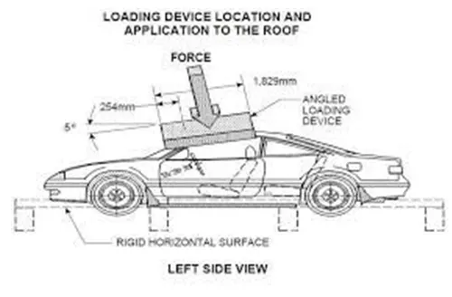
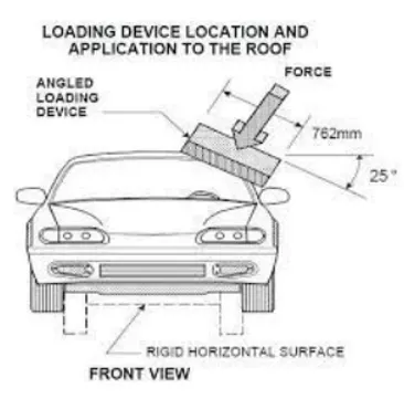
For the test, the passenger car shall be rigidly placed or positioned on a horizontal surface with the doors locked and the window closed. Furthermore, a flat, rigid block with a lower surface a rectangle measuring 30 inches wide by 72 inches long (762mm X 1829mm) shall not move more than 5 inches(127mm), measured as the distance between the original location of the lower surface of the test device and its location as the specified force level is reached, when it is used to apply a force of 1.5 times the unloaded vehicle weight (UVW) or 5000 lbs (22224N), whichever is less, to either side or forward edge of the vehicle.
This test can be conducted on either side of the roof structure, the front left or the front right side but not on both sides in one single test and still meet the requirements of the test. The rigid plate shall not move faster than 0.5 inches/second and the force applied on the plate shall not exceed the lesser of 1.5 times the unloaded vehicle weight (UVW) expressed in kilograms multiplied by 9.8 or 5000lbs (22240N).
Also, the direction of the force shall be downward and perpendicular to the lower surface of the rigid plate and such that it moves in a straight line without rotation. The duration of the test shall not exceed 120 seconds. The longitudinal axis of the plate is pitched forward at a 5 º angle as viewed from the side of the passenger car as shown below,
The lateral axis or the roll of the plate is such that it forms a 25 º outboard angle with a horizontal surface as viewed from the front of the passenger car as shown in below
Vehicle Roof Structure:
A roof structure for a vehicle body includes a roof opening defined by a pair of spaced-apart side rails, each having a flange extending inwardly and being vertically offset below the roof surface, and by front and rear headers, each having a flange defining a window opening. A roof panel assembly includes a roof outer panel and a pair of inverted hat-shaped reinforcement rails which underlie the outer side edges of the roof outer panel and include inwardly and outwardly directed legs abutting the underside of the roof outer panel. The outermost portion of the side edges of the roof outer panel is hem flanged over the outwardly directed flanges of the reinforcement rails so that the roof outer panel and the reinforcement rails define the roof panel assembly. The roof outer panel has fore and aft end flanges which overlie the flanges of the front and rear headers and are spot welded thereto. A bead of adhesive is placed on the inwardly extending flanges of the side rails and the roof panel assembly is lowered into the roof opening with the base wall of the reinforcement rails pressed onto the adhesive to attach the roof panel assembly to the vehicle body. The subsequent installation of the front and rear windows hides the spot welds.
DIFFERENT COMPONENTS OF CAR ROOF:
- Roof
- Front Roof Rail
- Center Roof Rail
- Rear Roof Rail
- Bow Roof 1
- Bow Roof 2
DIFFERENT SHEET METAL PROCESSES USED FOR MANUFACTURING THE BACK DOOR
DEEP DRAWING:
The metal deep drawing process is an effective method of manufacturing cups, cans, and other similar deep drawing products. The deep drawings have two main categories.
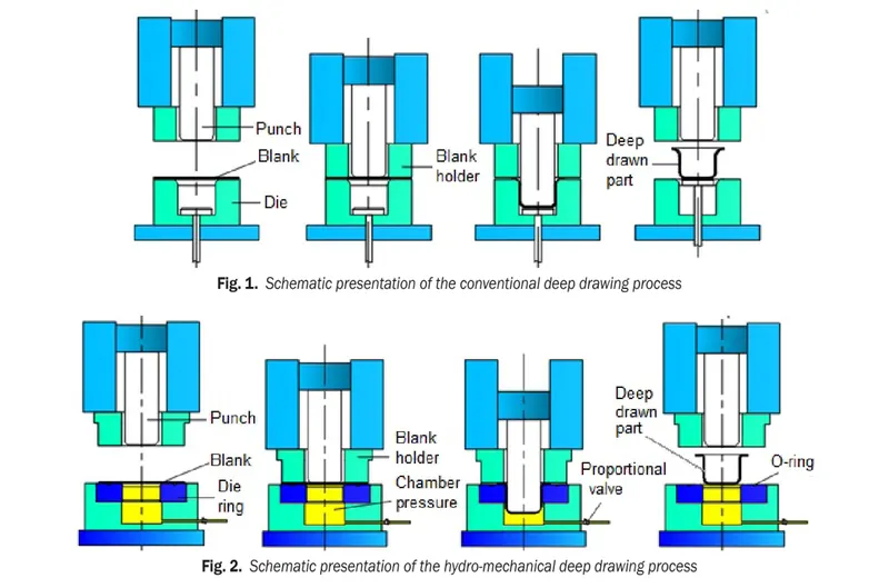
- FIRST- STAGE DRAWING: The blank shape of metal is placed on the die and in contact with the punch. When the metal specimen is a flat piece of sheet metal is used in forming and finishing the product. Initially, the punch moves in a downward direction. The outer rim of the blank is subjected to pure radial drawing (drawing toward vertical axes) between the die and blank metal. The metal becomes a bend and slides over the die and is also stretched between die and punch. The metal in the vicinity of the punch head and contact with it bend and slide over radii and stretch over the punch head.
- REDRAWING: The components drawn from the first stage again it is redrawn convert into more depth to form a cup shape in the die and punch. The second stage of drawing is called redrawing.
EMBOSSING:
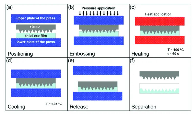
Embossing is a metal forming process for producing raised or sunken designs or relief in sheet materials using matched male and female roller dies, theoretically with no change in metal thickness or by-passing sheet or a strip of metal between rolls of the desired pattern. The metal sheet is drawn through the male and female roller dies producing a pattern or design on the metal sheet. Depending on the roller dies used, different patterns can be produced on the metal sheet.
Materials commonly used in the metal embossing process include:
- Aluminum alloys
- Steel alloys
- Zinc
- Copper
- Galvanized steel
- Brass
- Cold-rolled steel
BLANKING:
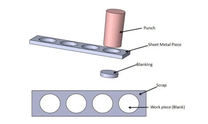
Blanking is a cutting operation of a flat metal sheet and the article punched out is known as blank. Blank is the required product of the operation and the metal left behind is considered as a waste.
PUNCHING:
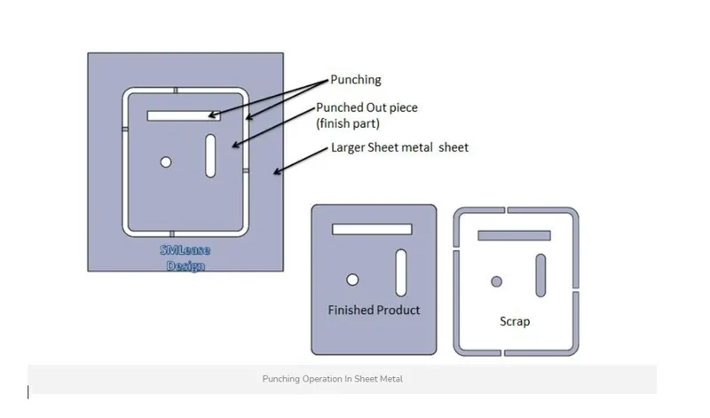
It is similar to blanking only the main difference is that the hole in the required product and the material punched out from the hole is considered as waste.
DESIGN REQUIREMENTS:
Heat
Bow–roof prediction Formula
W = [1.73 x 10^ (-3) x L] + [1.85 x 10^ (-8) x (R^2)/t] + [ 1.10x10^ (-3) x l] - 2.68
Judgement Condition: OK< 2.7> 3.1
Where
L = Roof Length in X-Direction[mm] (Roof dimension in 0-Y)
R = Roof curvature
R = 2 (Rx*Ry) / (Rx + Ry)
Rx = X curvature
Ry = Y curvature
t = Roof plate thickness [mm]
l = Bow Roof Span [mm]
Snow load Prediction:
This evaluation was performed in cold regions where snow occurs. Roof design must pass through these calculations to ensure that it has sufficient stiffness to withstand the load due to the accumulation of snow over the roof.
Snow load Prediction Formula:
Qr = [ Iy x t2] / [α x s x [(Rx + Ry)/2]2 x 10-8]
Note: The Qr value given over here is correct. There was a typo error in the formula given in the video.
Where,
α = My x Lx2 x 10-12 My = Y(Ly-Y)
Judgement condition = Qr ≥ 3.1
250 ≤ s ≤ 380
t = Roof plate thickness [mm]
Ly = Distance between the front and rear roof Rails on the Vehicle along with 0Y[mm]
Length of Roof panel with the center point between Roof rail Front /Rear as the front and rear reference point.
Lx = Distance between the Left and Right end of the roof on the Roof BOW [mm]
The width of the roof panel is exposed on the surface.
Y = Distance from Front Roof Rail to Roof BOW [mm]
s = Distance for which Roof BOW bears divided load [mm]
s = L1/2 + L2/2
Iy = Geometrical moment of inertia of Roof BOW (Y cross-section) [mm4]
Rx = Lateral direction curvature radius of roof panel Y cross-section on Roof BOW [mm]
Roof panel curvature Radius of the Length Lx in Front view
Ry = Longitudinal Direction curvature radius of the Roof panel X cross-section on Roof BOW [mm]
Roof panel X curvature radius of length s in Side view
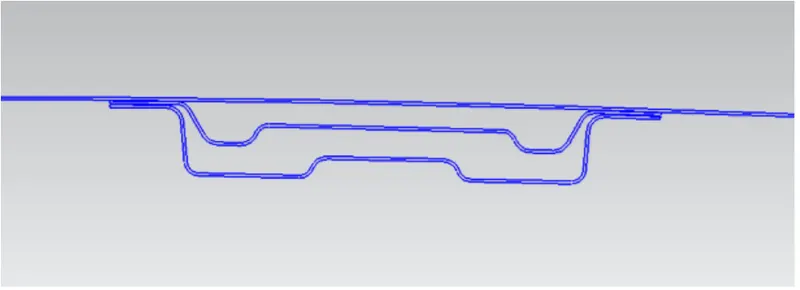
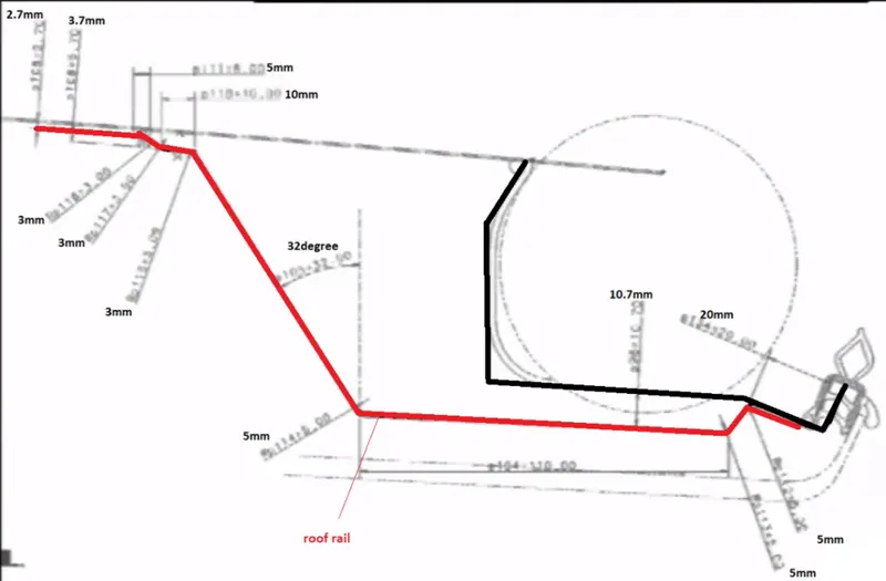
Master section of the rear roof rail
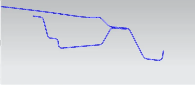
Master section of bow roof
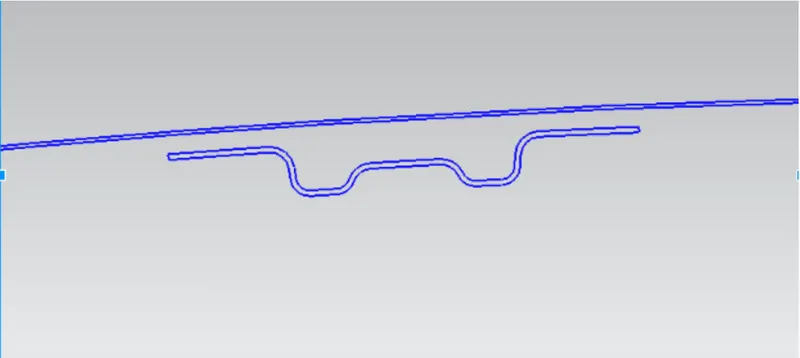
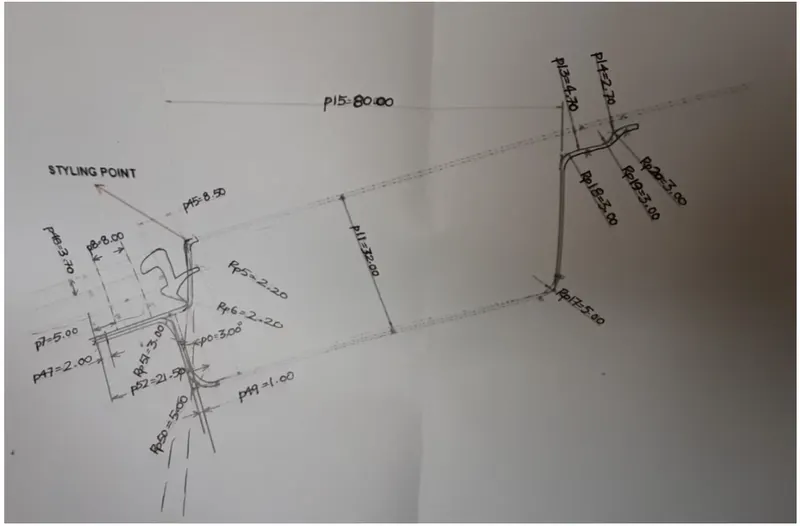
Master section of the front roof rail.
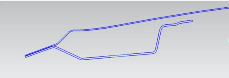
Master section of reinforcement center
Front roof Rail master section reference image
Rear roof rail master section reference image
DESIGN PROCEDURE:
EXTRACTED GEOMETRY: Creates an associative copy of bodies, surfaces, curves, points, etc.
OFFSET SURFACE: This command is used to create a surface by offsetting a set of faces.
OFFSET CURVE IN FACE: It is used to offset curves along a selected face or surface.
TRIM SHEET: It is used to cut off a portion of the surface.
BRIDGE CURVES: Creates a tangent blend curve between two objects.
THROUGH CURVES: Creates a surface through multiple sections where the shape changes to pass through each section.
THROUGH CURVE MESH: Creates a body through a mesh of sections in one direction and guides in another direction where the shape fits through the mesh of curves.
SWEPT: Creates a body by sweeping a section along one or more guides using various options to control the shape along with the guide.
STUDIO SURFACE: Creates a surface using any number of sections and guide strings.
FACE BLEND: Add tangent blend faces between a selected set of faces with a specified radius.
PROJECTED CURVE: Using this command we can project curves, sketches, or points onto the selected face or plane.
LAW EXTENSION: It creates a law-controlled extension from the base sheet, dynamically or based on laws for distance and angle.
EXTEND SHEET: Extends the sheet body by distance or to the intersection with another body.
EDGE BLEND: Rounds the sharp edges of the faces with a specified radius.
EMBOSS: This command modifies the surface by projecting a section along a vector, with options for end cap location and shape.
CURVE ON SURFACE: It is used for sketching a spline on the face or surface.
MIRROR GEOMETRY: Copies the geometry and mirrors them across a plane.
SEW: Sew is used to combine sheet bodies by sewing their edges together.
THICKEN: It gives thickness to the surface body.
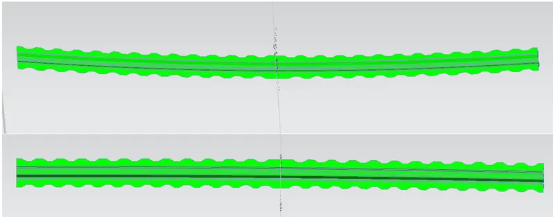
DRAFT ANASYS:
Roof:
BOW 1:
BOW 2:
REAR ROOF RAIL:
FRONT ROOF RAIL:
REINFORCEMENT CENTER:
CALCULATIONS:
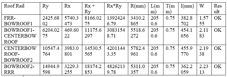
Heat Distortion Criteria:
Formula:
Bow–roof prediction Formula
W = [1.73 x 10^ (-3) x L] + [1.85 x 10^ (-8) x (R^2)/t] + [ 1.10x10^ (-3) x l] - 2.68
Judgement Condition: OK< 2.7> 3.1
Value for Calculation
L = Roof Length in X-Direction[mm] (Roof dimension in 0-Y)
R = Roof curvature
R = 2 (Rx*Ry) / (Rx + Ry)
Rx = X curvature
Ry = Y curvature
t = Roof plate thickness [mm]
l = Bow Roof Span [mm]
Answer:
L:2050.6
Rx:2425.6802
Ry:5740.3473
t:0.75
R = 2 (Rx*Ry) / (Rx + Ry) =3410.2865
I:382.8702
W = [1.73 x 10^ (-3) x L] + [1.85 x 10^ (-8) x (R^2)/t] + [ 1.10x10^ (-3) x I] - 2.68
W= [1.73 x 10^ (-3) x 2050.6] + [1.85 x 10^ (-8) x(3410.2865^2)/t] + [1.10 x10^ (-3) x 382.8702] – 2.68
W=3.5475 + [1.85 x10^ (-8) x (3410.2865) ^2/0.75] + [-2.2588]
W= 3.5475 + 0.2868 + (-2.2588)
W= 3.8343-2.2588
W=1.5755 …………………W=1.5755<2.75 (W is Ok)
L:2050.6
Rx:
Ry:
t:0.75mm
R = 2 (Rx*Ry) / (Rx + Ry) =5518.6272mm
I:454.1656mm
W = [1.73 x 10^ (-3) x L] + [1.85 x 10^ (-8) x (R^2)/t] + [ 1.10x10^ (-3) x I] - 2.68
W= [1.73 x 10^ (-3) x 2050.6] + [1.85 x 10^ (-8) x(5518.9272^2)/t] + [1.10 x10^ (-3) x 454.1656] – 2.68
W=3.5475 + [1.85 x10^ (-8) x (5518.9272) ^2/0.75] + [-2.1804]
W= 3.5475 + 0.7512 + (-2.1804)
W= 4.2984-2.1804
W=2.1183 …………………W=2.1183<2.75 (W is Ok)
L:2050.6mm
Rx:
Ry:
t:0.75mm
R = 2 (Rx*Ry) / (Rx + Ry) =5782.4961mm
I:455.9770
W = [1.73 x 10^ (-3) x L] + [1.85 x 10^ (-8) x (R^2)/t] + [ 1.10x10^ (-3) x I] - 2.68
W= [1.73 x 10^ (-3) x 2050.6] + [1.85 x 10^ (-8) x(5782.4961^2)/t] + [1.10 x10^ (-3) x 455.9770] – 2.68
W=3.5475 + [1.85 x10^ (-8) x (5782.4961) ^2/0.75] + [-2.1784]
W= 3.5475 + 0.8247 + (-2.1784)
W= 4.3722-2.1784
W=2.1938 …………………W=2.1938<2.75 (W is Ok)
L:2050.6
Rx:
Ry:
t:0.75
R = 2 (Rx*Ry) / (Rx + Ry) =5311.0357
I:362.2059
W = [1.73 x 10^ (-3) x L] + [1.85 x 10^ (-8) x (R^2)/t] + [ 1.10x10^ (-3) x I] - 2.68
W= [1.73 x 10^ (-3) x 2050.6] + [1.85 x 10^ (-8) x5311.0357^2)/t] + [1.10 x10^ (-3) x 362.2059] – 2.68
W=3.5475 + [1.85 x10^ (-8) x (5311.0357) ^2/0.75] + [-2.2588]
W= 3.5475 + 0.6957 + (-2.2819)
W= 4.5132-2.2588
W=2.2313 …………………W=2.2313<2.75 (W is Ok)
Heat Distortion Criteria
Snow load Prediction:
Formula:
Qr = [ Iy x t2] / [α x s x [(Rx + Ry)/2]2 x 10-8]
Value for Calculation:
α = My x Lx2 x 10-12 My = Y(Ly-Y)
Judgement condition = Qr ≥ 3.1
250 ≤ s ≤ 380
t = Roof plate thickness [mm]
Ly = Distance between the front and rear roof Rails on the Vehicle along with 0Y[mm]
Length of Roof panel with the center point between Roof rail Front /Rear as the front and rear reference point.
Lx = Distance between the Left and Right end of the roof on the Roof BOW [mm]
The width of the roof panel is exposed on the surface.
Y = Distance from Front Roof Rail to Roof BOW [mm]
s = Distance for which Roof BOW bears divided load [mm]
s = L1/2 + L2/2
Iy = Geometrical moment of inertia of Roof BOW (Y cross-section) [mm4]
Rx = Lateral direction curvature radius of roof panel Y cross-section on Roof BOW [mm]
Roof panel curvature Radius of the Length Lx in Front view
Ry = Longitudinal Direction curvature radius of the Roof panel X cross-section on Roof BOW [mm]
Roof panel X curvature radius of length s in Side view
Answer:
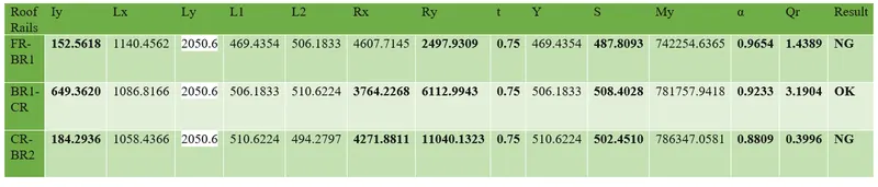
Lx1 = 1140.4562, Lx2 = 1086.8166, Lx3 = 1058.4366, Lx4 = 1043.1092
Ly (1,2,3,4) = 2050.6
Rx1 = 4607.7145, Rx2 = 3764.2268, Rx3 = 4271.8811, Rx4 = 3913.6685
Ry1 = 2497.9309, Ry2 = 6112.9943, Ry3 = 11040.1323, Ry4 = 16902.49210000
Y1 = 469.4354, Y2 = 5061.1833, Y3 = 510.6224, Y4 = 494.2797
Iy1 = 152.5618, Iy2 = 649.3620, Iy3 = 184.2936
L1 = 469.4354, L2 = 506.1833, L3 = 510.6224, L4 = 494.2797
S1 = 487.8093, S2 = 508.4028, S3 = 502.4510
My1 = 742254.6365, My2 = 781757.9418, My3 = 786347.0581, My4 = 769257.531
α1 = 0.9654, α2 = 0.9233, α3 = 0.8809, α4 = 0.8370
Qr1 = [ Iy1 x t2] / [α1 x s1 x [(Rx1 + Ry1)/2]2 x 10-8]
Qr1 = [ 152.5618 x (0.75) 2] / [0.9654 x 487.8093 x (4607.7145 + 2497.9309)/2] x 10-8]
Qr1 = [ 855.3160] / [470.9310 x (12622549.14) x 10-8]
Qr1 = 85.81 / 59.4435
Qr1 = 1.4389 …………………Qr=1.4389<3.1 (Qr isnot Ok)
Qr2 = [ Iy2 x t2] / [α2 x s2 x [(Rx2 + Ry2)/2]2 x 10-8]
Qr2 = [649.3620 x (0.75) 2] / [ 0.9233 x 508.4028 [(3764.2268 + 6112.9943)/2] 2 x 10⁻⁸]
Qr2 = [ 365.2661] / [469.4083 x [(4938.6105) 2] x 10-8]
Qr2 = 365.2661/ [ 469.4083 x 24389873 x 10-8]
Qr2 = 365.2661/114.4880
Qr2 = 3.1904 …………………Qr=3.1904≥3.1 (Qr is Ok)
Qr3 = [ Iy3 x t2] / [α3x s3 x [(Rx3 + Ry3)/2]2 x 10-8]
Qr3 = [ 184.2936 x (0.75) 2] / [0.8809x 502.4510 x [(4271.8811 + 11040.1323)/2]2 x 10-8]
Qr3 = 103.6651 / [ 442.6090 x [(15311.0134)/2] 2 x 10⁻⁸]
Qr3 = 103.6651 / [ 442.6090 x [7655.5067] 2 x 10⁻⁸]
Qr3 = 103.6651 / [ 442.6090 x 58606782 x 10-8]
Qr3 = 103.6651 / 259.403
Qr3 = 0.3996 …………………Qr=0.3996<3.1 (Qr isnot Ok)
Section Modulus:
Section modulus is a geometric property for a given cross-section used in the design of beams or flexural members. Other geometric properties used in the design include an area for tension and shear, the radius of gyration for compression, and the moment of inertia, and the polar moment of inertia for stiffness. Any relationship between these properties is highly dependent on the shape. There are two types of section moduli
- Elastic section modulus
- Plastic section modulus
The Elastic Section Modulus is defined as,
S = I/y
Where,
S: is the Section Modulus
I: is the second moment of area (or area moment of inertia, not to be confused with the moment of inertia)
y: is the distance from the neutral axis to any given fiber. It is often reported using y = c, where c is the distance from the neutral axis to the most extreme fiber
Y1 = 61.4329mm, Y2 = 27.8431mm, Y3 = 27.5476mm, Y4 = 27.1119mm, Y5 = 114.6279mm
I1 = 8.3914x103mm4, I2 = 152.5618 mm4, I3 = 649.3620 mm4, I4 = 184.2936 mm4, I5 = 6.5165 x104 mm4
S = I/y
FRONT ROOF RAIL
S1 = 8.3914x103 mm4/61.4329mm
S1= 136.5945mm3
BOW ROOF
S1 = 152.5618 mm4/27.8431mm
S1 = 5.4793mm3
REINFORCEMENTS CENTER BOW
S1 = 649.3620 mm4/27.5476mm
S1= 23.5723mm3
BOW ROOF
S1 = 184.2936 mm4/27.1119mm
S1= 6.7975mm3
REAR ROOF RAIL
S1 = 6.5165 x104 mm4/114.6279mm
S1= 568.4131mm3
Conclusion:
- All reinforcement BIW parts of the roof are designed according to the input data provided by the styling team. Designed parts will be submitted to the CAE team to carry out further FEM analysis to obtain numerical data to improve the design.
- Made the curvature study and analysis the design for Heat distortion are found OK.
- Made the curvature study and analysis the design for Snow Load are found OK. But we found Bow roofs 1 and 2 have NG (not Good), So we have to ask the styling team to modify the surface with curvature.
* Also, we can provide emboss in the roof show. The Embosses have radically increased the strength of the roof.
- Moment of inertia, Section Modulus, and Draft analysis is carried out to check the feasibility of manufacturing are found need additional process for roof rear end to manufacturing.