Project 2
Body in white (BIW) refers to the stage in the automobile manufacturing in which a car body’s components have been joined together, using one or a combination of different techniques: welding (spot, MIG/MAG), riveting, clinching, bonding, laser brazing, etc.
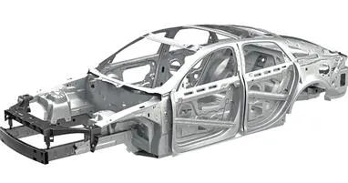
Body in White, or BIW, is a stage in the production of automobiles in which all sheet metal components
such as the roof, body side, underbody, backdoor, cross members, and other components are welded together and the resulting body is dipped in a primer solution, which has a greyish color and thus gives the body its name. The car's shape is determined by the BIW, which is obtained after welding and before painting.
BIW is mainly categorized as:
Body side
Underbody
Closures
Roof
Fender
Reinforcements
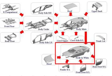
BODY SIDE consists of:
Body side outer
Body side inner
It generally refers to both sides of the car that is left and right sides. It mounts various BIW components like A-pillar, B-pillar, C-pillar, Panel side sill, etc.
UNDERBODY consists of:
Front end under frame: This is the compartment where the engine and other components of an automobile like battery, radiator, etc. mount.
Main floor: This is the compartment where the interior parts like seats; infotainment panels etc. will be mounted.
Rear end under frame: This compartment shapes the rear end of the car. This is what provides space for mounting rear closure parts and boot space.
CLOSURE components consist of:
Front door: Two front doors on each side.
Rear door: Two rear doors on each side.
Hood: To cover the engine compartment.
Trunk lid: To cover the interior and boot space.
ROOF consists of:
Roof inner
Roof outer
FENDER: The component seats between the side body and front end under the frame.
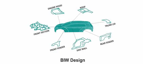
The below image shows precisely what a BIW of monocoque consists of
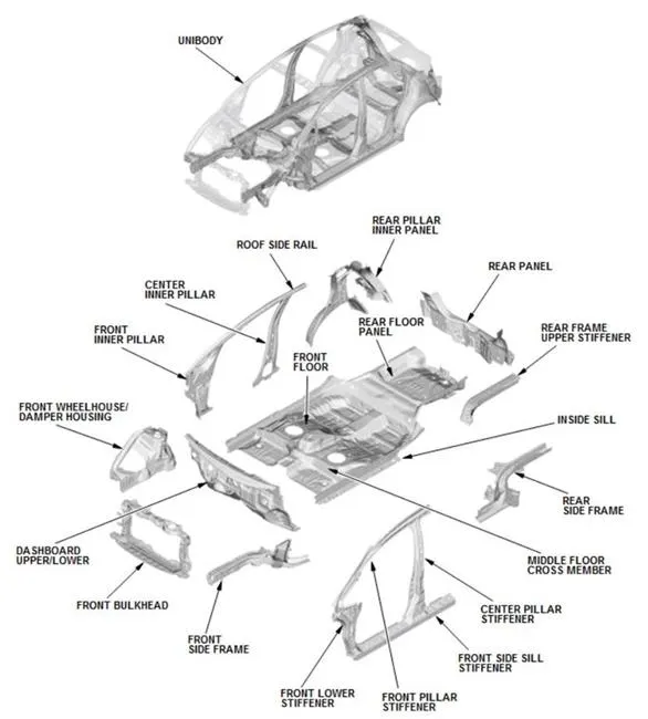
A nomenclature in BIW is naming every part of the body. These names can be said as subparts of the already categorized parts above. The nomenclature differs a little bit from region to region but the overall idea is to name individual automotive sheet metal components. The below images show the nomenclature of BIW:
The terms are standard but they differ in some countries.
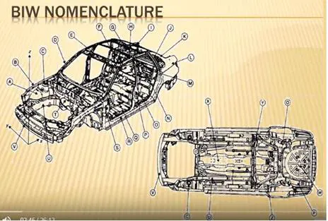
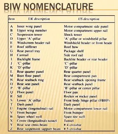
As automotive industries spread worldwide, the terms and standards will be different for similar components.
For example, one component of BIW is known as the inner wing panel in the UK description another side of the same component of BIW is known as the Motor compartment side panel in the US description.
The fixture is a holding device that holds the workpiece to be processed. In general, fixtures are designed using the 3-2-1 principle. Further, the fixture should firmly hold the workpiece without causing vibrations, distortions, or stresses in the workpiece, and also fixture should not disturb or interfere with the processing of the workpiece.
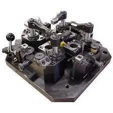
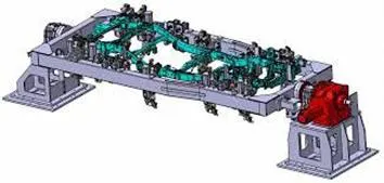
Types of fixtures:
Production fixture
These fixtures are used for mass production. Since these fixtures are used for mass production, they should be simple, rigid, and hard. These fixtures should be periodically maintained at regular intervals to avoid errors and repairs. The design of the fixture should be in such a way that it should be easy to load and unload the workpiece within seconds to increase the productivity of the processing/assembly.
Pre-production operation fixture
These fixtures are newly designed fixtures for the new products or parts. These may be complex, manual, and heavy based on the application. These can be referred to as prototype fixtures. Once the preproduction operation fixture functions properly, then modifications are made to improve and to make it simple and reliable. These fixtures are used in special cases or during the initial or trial stages of processing/production
Checking fixture
These fixtures are used for checking and inspection purposes. No processing is done in these fixtures. These fixtures consist of gauges for checking the dimensions and tolerances and their accuracies. In some checking fixtures, fixtures are fixed and CMM devices check the geometrical accuracies.
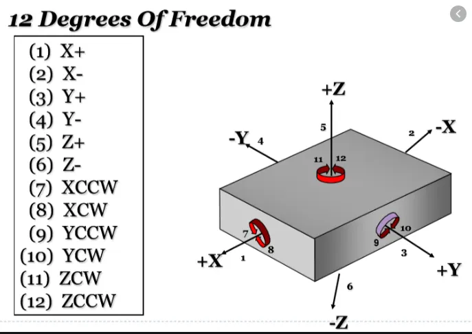
the fixture is designed based on how the workpiece is fixed on the fixture. All the Degrees of Freedom of the workpiece are to be constrained.
The 3-2-1 principle is used.
The workpiece has twelve Degrees of Freedom. six transitional DOF and 6 rotational DOF.
Transitional: X, -X, Y, -Y, Z, -Z.
Rotational: Clockwise around the X axis (CROT-X); Anticlockwise around the X axis (ACROT-X); Clockwise around the Y axis (CROT-Y); Anticlockwise around the Y axis (ACROT-Y); Clockwise around the Z axis (CROT-Z); Anticlockwise around Z axis (ACROT-Z).
The rotational DOF has to be constrained.
3-2-1 principle.
First, the workpiece is constrained by 3 pins on the below surface. This locks the Y DOF, clockwise around the X axis (CROT-X); Anticlockwise around the X axis (ACROT-X) the Clockwise around Z axis (CROT-Z); Anticlockwise around the Z axis (ACROT-Z).
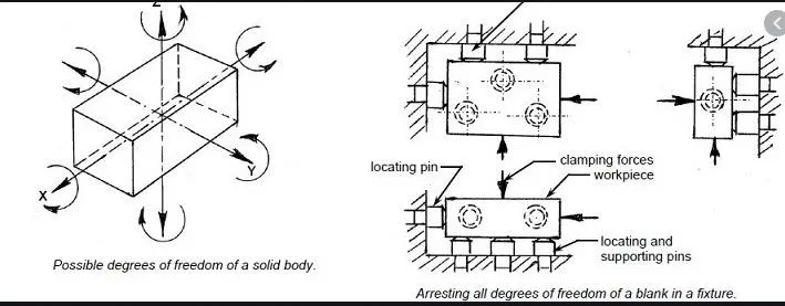
Then another side perpendicular to the below surface is constrained by 2 pins. This locks -Z and +ZDOF Clockwise around the Y axis (CROT-Y); Anticlockwise around the Y axis (ACROT-Y).
Then any one side perpendicular to both the below and the other 2 sides of the workpiece is constrained by 1 pin. This locks X DOF.
The part is now fully constraint and cannot move
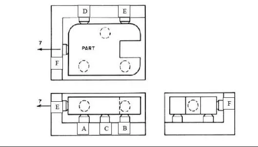
The 3 points are used as 3 points to define a plane. Four points cannot be used due to the irregularity of the surface in the real world.
The BIW assembly line is where different types of panels are joined together in each specified zone like the Underbody zone, Hood zone Etc.
These zones are further subdivided into stations, where various processes like welding gluing, and inspection are done to the part of that particular zone before they are assembled. For instance, in the roof zone, various reinforcement is to be added before they are married to the side zone.
The BIW assembly line can be classified as follows:
Tools
Grippers
Stands
Miscellaneous
A tool is a fixture that consists of several different units together to hold a car panel or assembly.
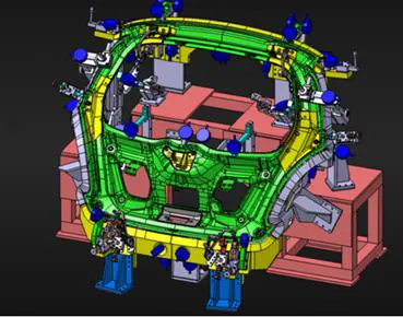
Geo Tool:
A geo tool is a fixture in which the geometry of the panel which is welded together is defined accurately.
In the geo fixture, two panels will be loaded and welded together.
The pin tolerance for the geo fixture is about -0.15mm.
Re-spot Tool:
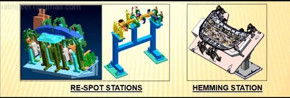
A re-spot tool is a fixture where already welded panels are brought to be welded further.
For example, on a certain panel, we needed to have 50 welds but due to assembly line constraints we managed to achieve 30 on the geo tool, then the remaining 20 will be achieved on the re-spot tool.
The pin tolerance for the re-spot tool is -0.28mm.
Marriage or hemming tool:
A marriage or hemming tool is a fixture in which the inner panel and outer panel are joined together.
Hemming is not done for every part but only for those parts where we want to join two panels without other joining processes as it may affect the aesthetics of the car.
Hemming can be found on the Hood, Back door, etc.
Checking stations:
It is used to check the automotive part or assembly to ensure all the coordinated, relative dimensions and positions are as per tolerance. It can be classified as follows:
Gauge type checking fixture is where the workpiece is held and various gauges are introduced to ensure the dimensions and repeatability.
Fixed type checking fixture is where the workpiece is fixed using clamps and pins and the Coordinate Measuring Machine is used to measure the coordinates of different points of the panel and compare it with the nominal value and give its report to rectify any errors.
Automated checking fixture is where the automated setting is being done through sensors, PLCs, switches, etc, to give a signal in case of any irregularities which can be rectified. As it is expensive, it is not widely used.
Grippers Stations
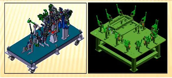
A gripper is a device that enables the holding of an object to be manipulated. The easier way to describe a gripper is to think of the human hand. Just like a hand, a gripper enables the holding, tightening, handling, and releasing of an object. A gripper is just one component of an automated system. A gripper can be attached to a robot or it can be part of a fixed automation system.
Different grippers are used in BIW as follows,
A) Material handling gripper
As the name suggests These grippers are used for material
These grippers can pick up assembly from one station & will drop the assembly at another
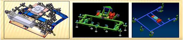
B) Process grippers
These grippers are used to carry out some specific processes like gluing, welding, and riveting in addition to material handling.
The gripper will go under gluing stand in case of gluing process & will go under the pedestal weld stand in case of the welding process.
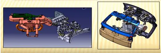
C)Combo Gripper
Combo grippers are the ones that can carry out multiple tasks like it can do material handling & also it can carry out specific processes like gluing, and welding as well.
Weld gun + Gripper
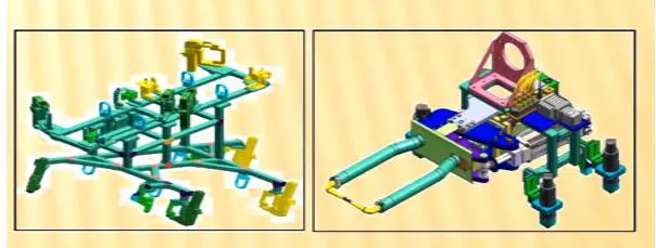
D) Dual Gripper
These are two-sided in case when we want one LH & one RH part, these grippers are used. It can handle the material from one station to another station
Gripper + Gripper
3) Stands Stations
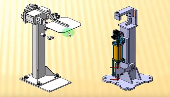
Stands are used to hold the part when not in use or also it is used to mount some parts or bodies on it.
Different stands are used in BIW
A) Pedestal stands
The Weld gun is mounted on the fixed stand which is mounted to the floor The gripper can carry the panel under the stand to do the operation.
B) Gluing & sealer stand
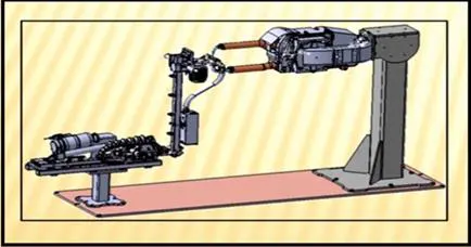
Gluing gun or sealer gun is fixed to a welded or a standard stand which is grouted to the floor
C) Docking Stand
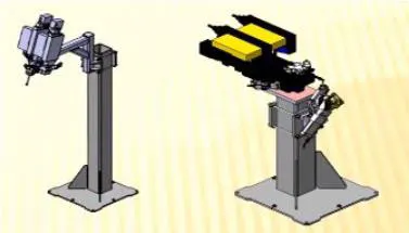
The robots have some limitations such as the payload capacity of the robot & also due to the lack of
When we select the robot for multitasking it can't do both the task simultaneously due to
In this kind of case, we add a docking stand to put some equipment that is not in use for the current operation but will be required for next
Hence the robot can drop a gripper or gun & pick up the following operation equipment to complete the task from the docking
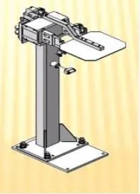
D) Date stamp stand
Every manufactured product has some data to be stamped or to be embossed on it like serial no, batch no, and Date for some future reference, or data collection.
The required data is stamped or embossed by using the stamping device mounted
4) Miscellaneous stand
A) Curing
After gluing it needs some time to cool down, so we put the assembly on some belts & it will take the panel to another station & meanwhile gluing will cool down.
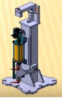
B) Buffer stand
After some operation, we can put the no. of assemblies in this stand which is buffer stock & it can be transported to another station in easy They are also used to store the inventory while the machine is undergoing some maintenance.
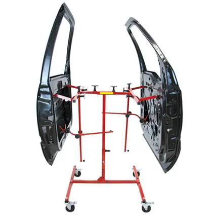
C) Take out trolleys
It used to take out some panels for inspection to rectify whether the process is going in the right or not between the cycle.
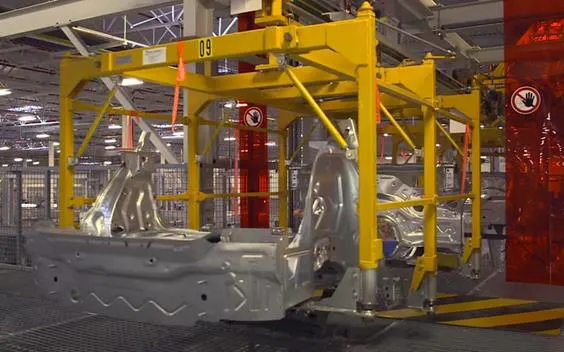
D) Conveyor
The conveyor is the rotating path that transports the parts to the next station which is kept over it.

Basic terminologies used in the BIW fixture
The following terminologies are used in BIW
A) NC/Mylars/Fingers
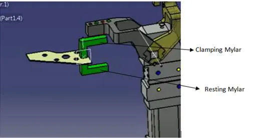
Mylars are the component that holds the panel while These are placed from the top side & the bottom side also. The top side of Mylars is called Clamping Mylars & the bottom side of Mylars is called Resting Mylars. Every clamping Mylars have resting Mylars. It doesn't allow deformation of the part due to welding stresses.
B) Principle locating point (PLP)
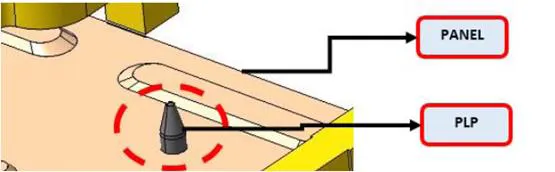
These are the points that are used for the accurate location of the part to maintain the geometry of the part. There are lots of holes on the panel which are not accurate due to the stamping operation. The PLP is defined in the drawing. The positional dimensions or relative dimensions are very precise in stamping & fixtures also.
C) Risers
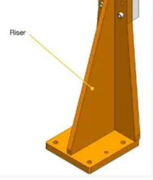
Risers are of different types like L-typer rises, square tube riser Riser is the manufacturing part that gives height to the assemblies.
D) Blade
Blades are plates mounted on other parts like cylinders, arms, etc. are mounted on the blade.
E) Shims
Shims are small part that comes with a thickness of 0.1mm, 0.2mm, 0.5mm, etc. These will compensate for the stackup tolerance which reflects in the panel holding part called We give tolerance to all the parts of the fixture. Due to this tolerance, the Mylars will either lift or goes down from their defined position.
If the Mylars go down from the defined height it will make an impression or dent on the panel.
If the Mylars lift then there will be a distortion due to welding stress. To adjust the Mylars At its defined position we use shims so the panel won't be deformed & also don't get any impression on it.
F) Rough locators
The operator can place the part in the wrong orientation The rough locator will work as a guide while placing the part in the fixture & the part will be loaded in the desired orientation. It is a part of foolproofing.
G) Hardware
Hardware is like the Hex head bolts, Allen Bolts, Hex nuts, Spring washers, Self-locking nuts
H) CMM
CMM stands for coordinate measuring machine. It is a device that measures the geometry of physical objects by sensing discrete points on the surface of the object with a probe. It generates a report by comparing the data with the CAD file data.
I) Unit
The fixture is the assembly of different types of units to form a part. There are different units like pin unit, base unit, clamping unit, etc.
J) Number plates
The number plate is the aluminum embossed plate placed on each unit for quickly recognizing the part unit.
K) Nameplate
The data like manufacturing company name, fixture type, and Fixture weight are embossed on the plate & joined to the fixture.
L) Clamp Arm
The clamp arm is the part of the clamp unit which moves an Over clamp arm the Mylars are mounted.
M) Pivot
It is an axis about which the clamp arm will rotate
N) Class A Surface/Skin surface
The outer panels of the car like the hood, door, backdoor, fender, and roof are visible to the customer.
The outer panels should be aesthetically very good. No scratches or dent is acceptable over it.
While designing the fixture to the skin surface the clamping material should be soft, so that it could not able to left any impression or dent over the skin. generally, nylon or PU material is used for clamping purposes.
O) Reed switches & sensors
These are the electric components used in automated the reed switch is an electrical switch operated by an applied magnetic field. The detects whether the panel is loaded or not is done by sensors.
FIX PIN UNIT -
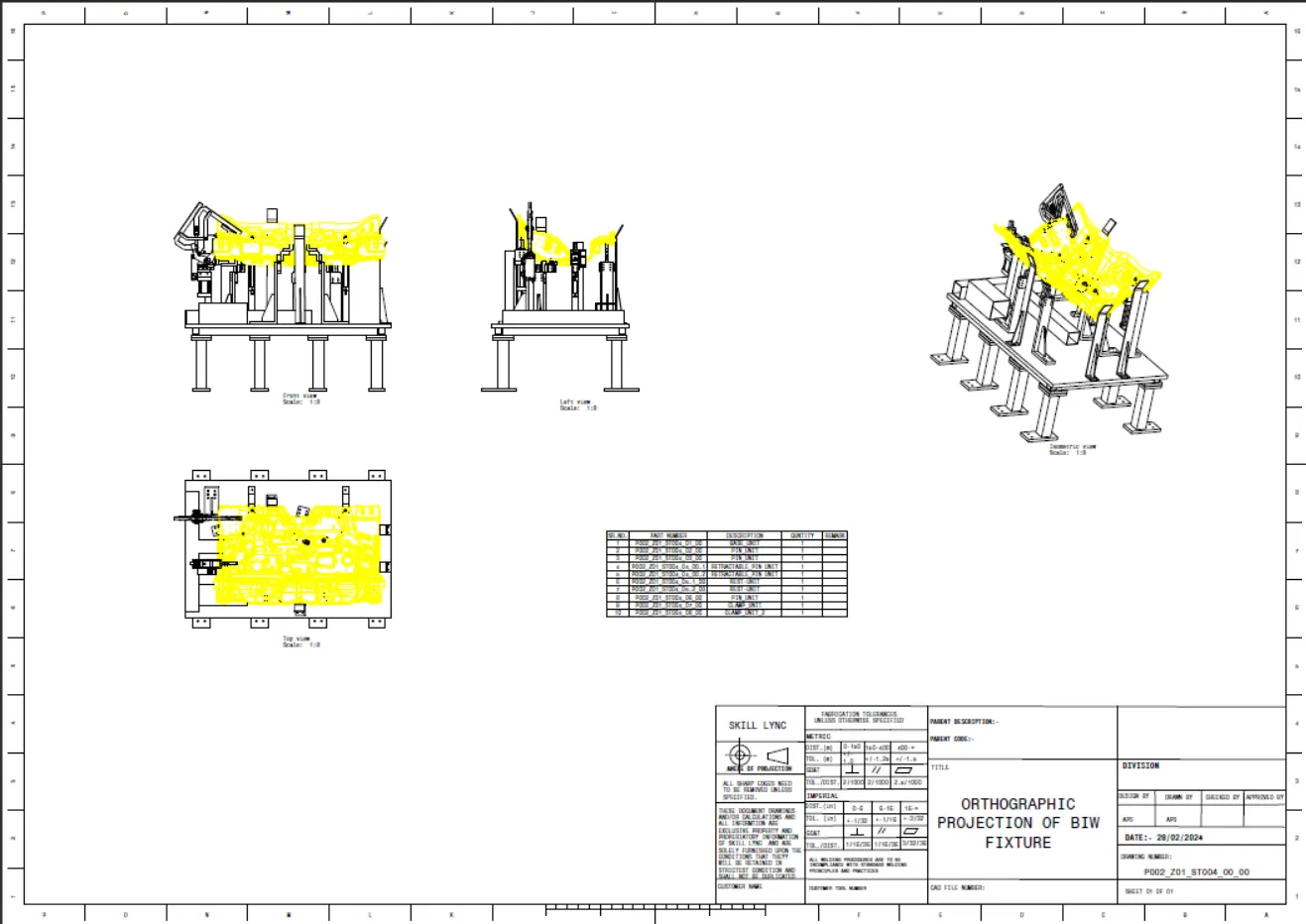
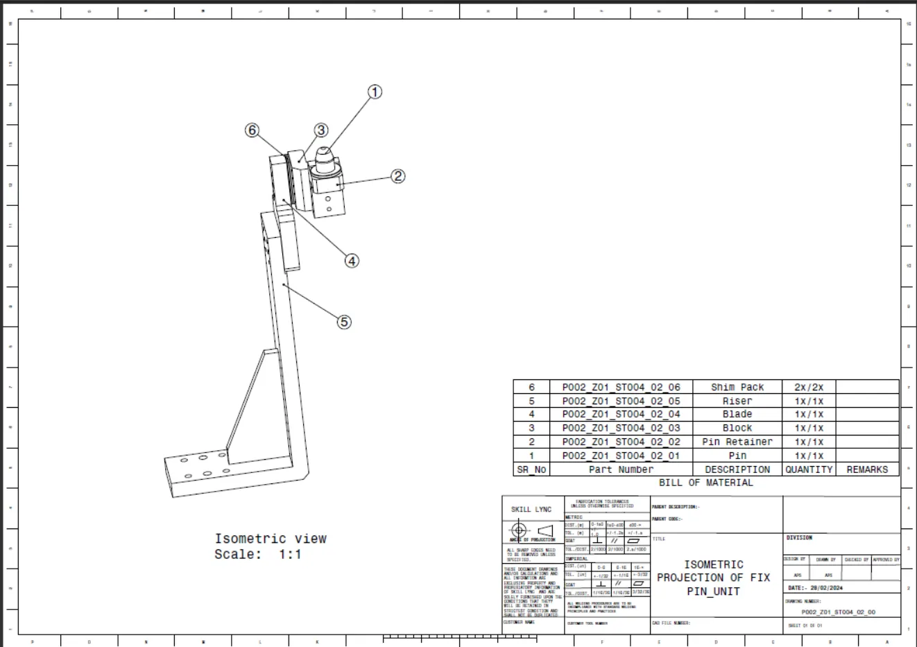
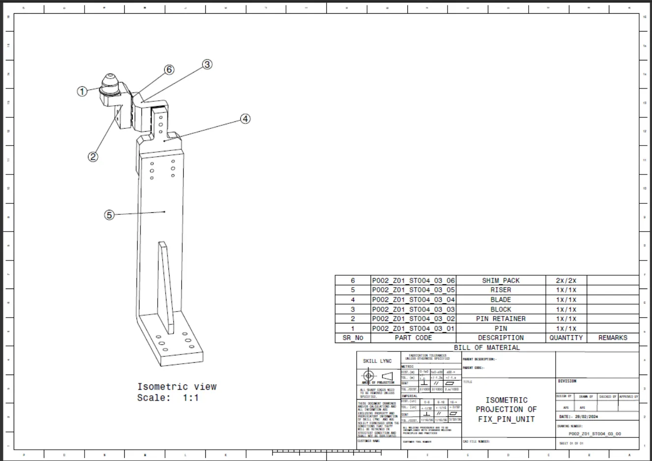
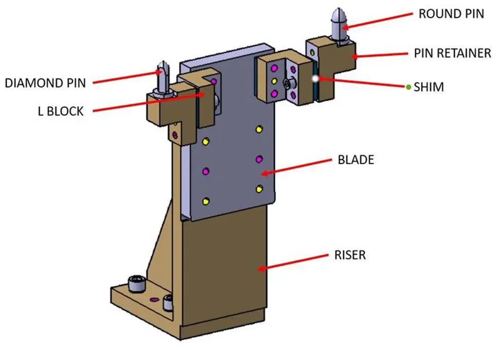
An assembly of standard and manufacturing parts consisting location pin is called a Pin unit. A pin unit in which the pin’s position
is fixed is called a Fixed Pin Unit. The pin unit is used to lock the rotational position of the panel. Round Pin is used to control the panel in
two directions while Diamond Pin is used to control the panel in one direction.
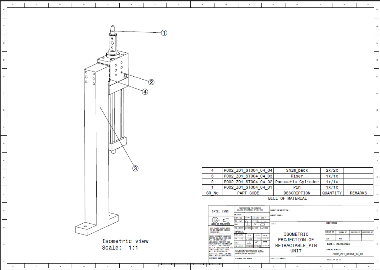
Retractable Pin Unit
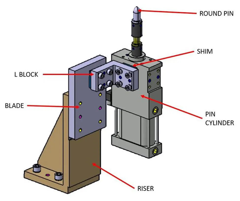
An inline Retractable Pin unit consists of one Pin cylinder that operates the pin in one direction. In this unit Pin is directly mounted
on the cylinder and it is a must to have the pin and cylinder in line with the hole or slot of the panel. The pin cylinder is controlled in
two directions with the help of shimming. The below picture is an example of an inline retractable pin cylinder.
Type of Pin unit:
Fixed pin unit: In this type of unit, the pin is fixed using a pin retainer and riser
Retractable pin unit: In this type of unit, there is the provision of moving of pin in the Up- down direction.
RETRACTABLE PIN UNIT:
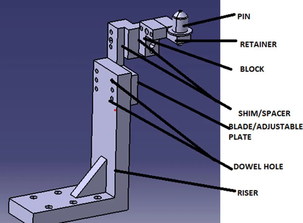
A retractable pin unit is a unit designed to locate the car panel using pins, but the entire pin package parts will be mounted on the retractable pneumatic cylinder.
In line, the Retractable Pin unit consists of one Pin cylinder which operates the pin in one direction. In this unit Pin is directly mounted on the cylinder and it is a must to have the pin and cylinder in line with the hole or slot of the panel. The pin cylinder is controlled in two directions with the help of shimming. The below picture is an example of an inline retractable pin cylinder.
Pin cylinders have various stroke sizes like 30mm,40mm, and 60mm. Cylinder. Uses of cylinders depend upon the area and availability while building the fixture.
Purpose of PIN Unit:
As by the 3-2-1 locating principle, introducing two pins helps to arrest the 6 degrees of freedom (4 axial and 2 radial movement) whereas the other 6 degrees of freedom are arrested by introducing a minimum of three supports.
Typically, the locating pins are used to locate a body part in a position sufficiently accurate to execute a welding process
The body part is constrained by a set of appropriately locating pins so total constraint by locating pins should be fully constrained at all times to prevent any movement.
Fundamental of PIN Unit:
It is necessary to have two pins to locate a car panel. One pin must arrest 4 ways (4 translation) and the other must arrest 2 ways (2 rotational) of a car panel.
The pin should engage 3-5 mm from the car part entry surface.
All pins should be accommodated with 2 ways adjustable shims irrespective of the direction of arresting.
The round pin should be used in case of 4-way arresting of the car part if the hole is round.
The round pin should be used in case of 2 way arresting the car part if the hole is round.
Diamond pins can be used for 4-way arresting of car parts only if the hole is round.
Diamond pins can be used in 2 ways to arrest the car parts only if the hole is slot.
The axis of the car panel hole and the axis of the pin should be the same.
Requirement:
Pin-Pin is the part that locates the car panel. It can be a male part or a standard part.
The Pin Should be grinding surface on a shaft with fits onto which the pin retainer
The mounting surface of the pin should be finely machined.
The pin should have a step machine surface to lock the rotation, which matches with pin retainer
All machined planes should be perpendicular to the axis of the pin Shaft.
The pin must have a provision like a tapped hole from the bottom or a V-groove from the side.
A pin must be hardened (Heat treatment) & Black oxide finished in general.
Typically, locating pins are used for controlled, fine tolerance positioning of, for example, a pallet that is moved along one axis, where the drive mechanism is not accurate and stable enough to place it in a position sufficiently accurately to execute a particular process, the use of locating pins may be the best solution.
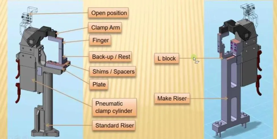
Block/ L Block :
These parts are mainly used to accommodate the shimming directions as per fundamentals in general, also in some cases used for other design feasibility.
Shims/Spacers:
Shims and Spencers are some Standard parts in general, which are used for adjustments of locators (NC Blocks and Pin retainers) for desired value for the precise working of a unit concerning car parts. In general, to adjust the design to manufacturing deviation.
CLAMP UNIT:
Clamps are versatile tools that serve to temporarily hold work securely in place.
A Clamp unit is a unit designed to clamp/ hold the car panel at a certain location.
Its purpose is to hold the panel at that place with the application of force.
TYPES OF CLAMP UNIT:
Power Clamp unit.
Swivel cylinder clamp unit.
CLAMP PLAN:
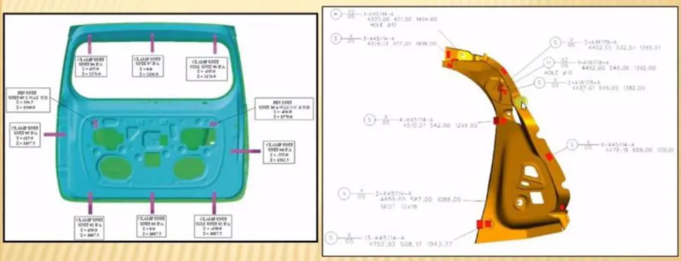
The customer provides the clamp plan which consists of the position of the clamp, pins, rests dump, etc.
It has the exact coordination of these components and in addition, it also has the hole’s dimensions and tolerances.
As this is critical input data, it must not be modified.
In case the spot for weld and the clamp position is nearby and it may create a problem later and there is a need to change the position of the clamp, the same must be done so with the permission of the customer as it will be easy for the customer to make changes from his side also.
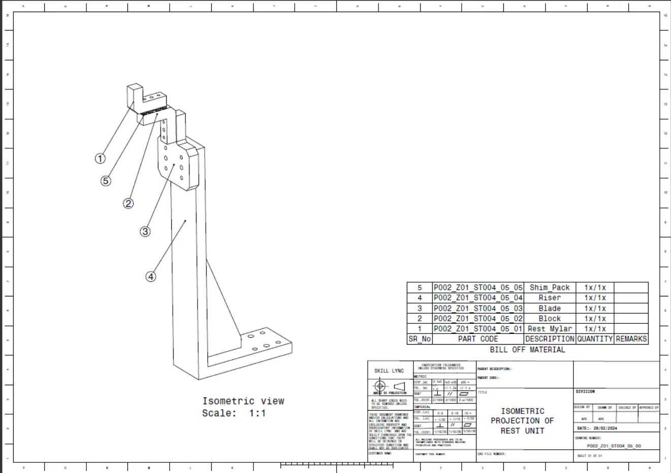
REST UNIT:
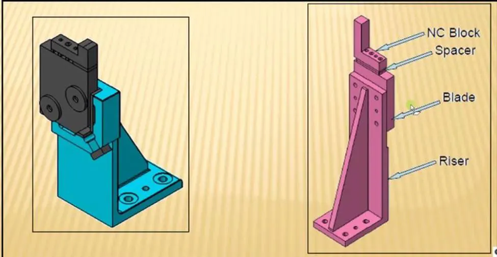
A rest unit is a unit that is designed to support or rest the car panel on it.
Its sole purpose is to rest the panel onto it and thus no force or clamping is done.
However as it is a simple design, it can be combined with other units to reduce the cost of the overall project.
For example, it can be used along with a locating unit to locate and rest the panel or with a clamp unit to clamp and rest the panel.
The rest unit, locating unit, and clamp unit can be used together in one single project.
Components of Rest unit:
NC block
Spacer/ Shim pack
Blade
Riser
IMPORTANT NOTES:
Clamping: The car panel will rest on the rest unit, also it resists the clamping unit for the clamping force of the finger and thus clamp the car panel.
Resting: The car panel will rest on the rest unit, also it resists the clamping force of the finger and this clamps the car panel.
Forces act in clamp & Rest Unit:
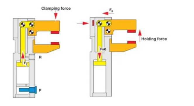
To design a clamp unit, we have considered some forces that act in a clamp unit for clamping purposes. The force acts in the clamp unit are.
Clamping Force
Holding force
Clamping force is not the same as holding force.
Clamping Force:
Clamping force signifies the force applied to the workpiece by the drive mechanism via the clamp arm during gripping or clamping operations.
Clamping force = 48 * S3
Holding Force:
Holding force, on the other hand, denotes the maximum force after locking the knee-lever (over-center position) that can be applied by the workpiece on the gripper/clamp arm without destroying the mechanism. Therefore, Particular attention must be paid to the maximum holding force when, for example, during the production process (welding, bonding) there is a possibility of distortion of the component or if the clamp arm is used as a fixed stop.
Base Unit:
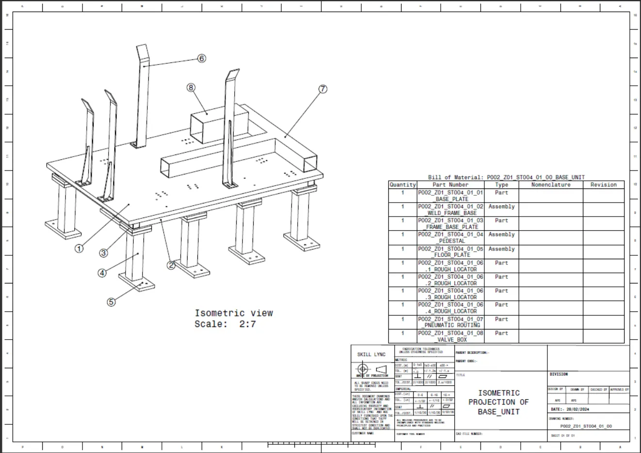
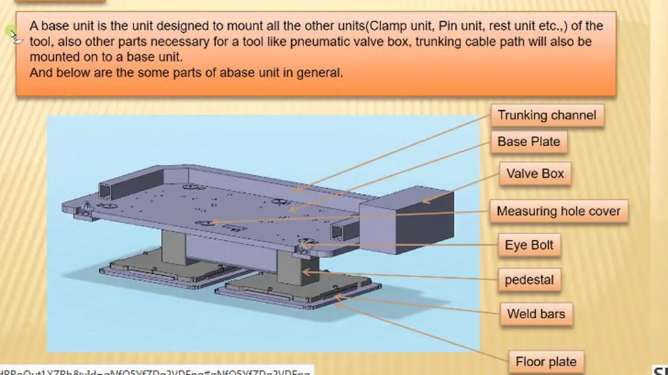
The base unit is the unit of the fixture which is designed as such so that other units of the fixture can be mounted on it. Apart from these units, other necessary tools like a pneumatic valve box and trunking cable path will also be mounted on the base unit.
The base unit is the fundamental component of the fixture because all other components are mounted over it.so every fixture has a base unit. The base unit design is different according to the panel, Design of the clamp system, location system, etc.
Parts of the Base Unit:
Base plate Pedestal
Trunking channel
Valve box
Eyebolt
Floor plate
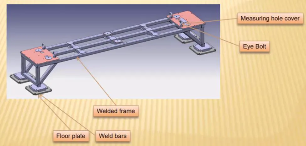
Welded Base Unit:
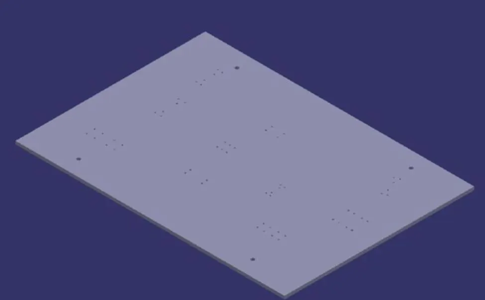
1. BASE PLATE:
A base plate is a machined plate of 25 to 40mm thickness made of steel and aluminum on which the holes are drilled to mount individual units like clamp unit, pin unit, rest unit, etc.
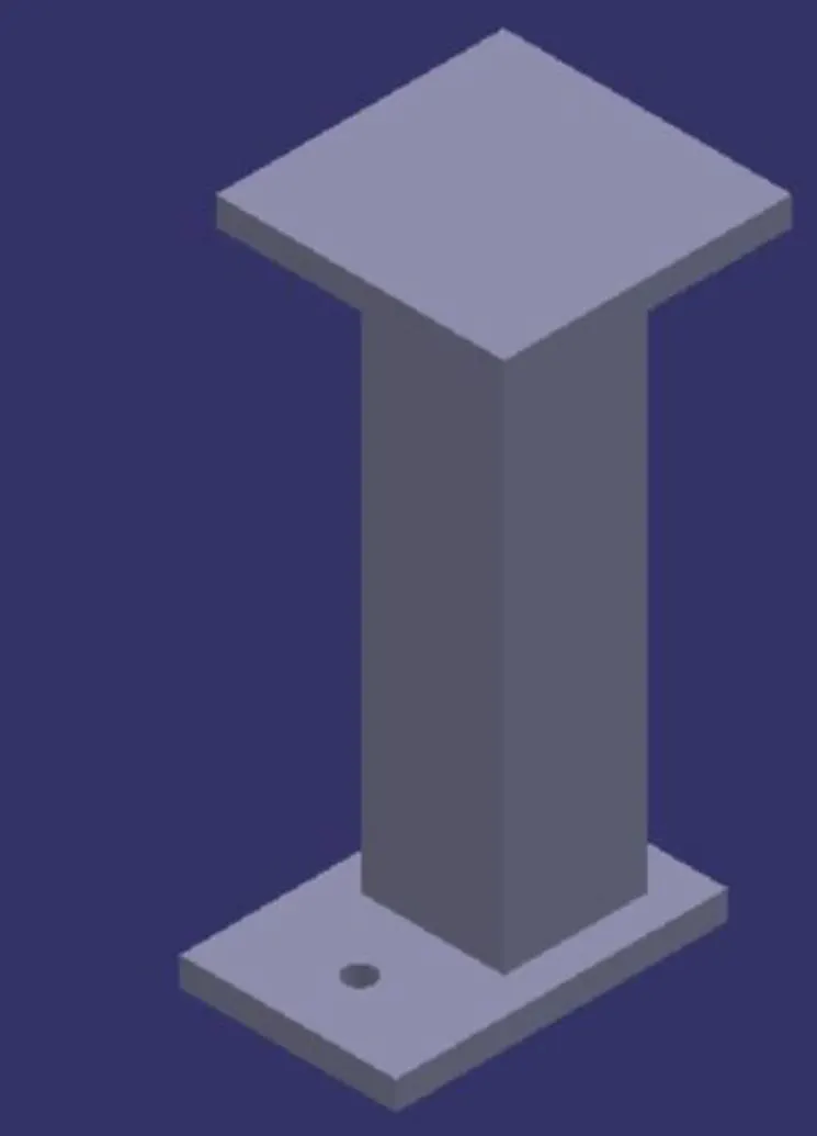
2. PEDESTAL:
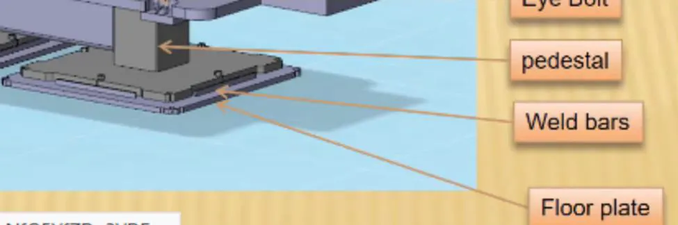
A pedestal is a part that connects the base plate to the floor plate. A pedestal is a standard part in general and in some cases, it can be a welded frame integrated with the base plate.
A standard pedestal can be of different heights and different sizes.
Depending on the size of the base plate, the number of pedestals varies for load distribution.
Pedestals are of different types with different inclinations.
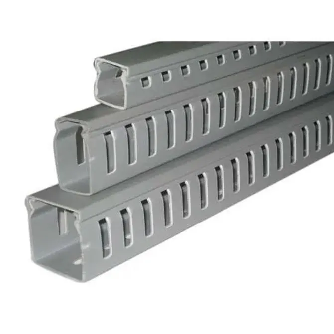
3. Trunking Channel:
The Trunking Channel is a duct that carries all the electrical and pneumatic connections(wires and pipes) for units of the tool. It has a thickness of a few millimeters.
4. Valve Box:
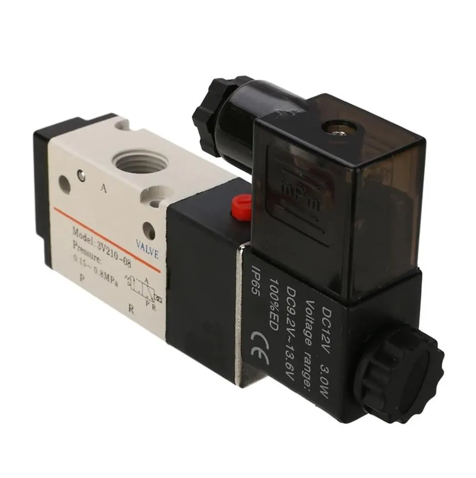
The valve Box is a standard part that contains all the valves for the pneumatic units. The valve box is the box that includes different solenoid valves. The pneumatic fixtures work on air pressure provided to it. So the arrangement of the air pressure inlet & outlet is done within this valve box.
The trunking channel includes all the pressure inlet cables going to the pneumatic parts of the fixture & protects them from damage while the operation is in process.
5. Eye Bolts:
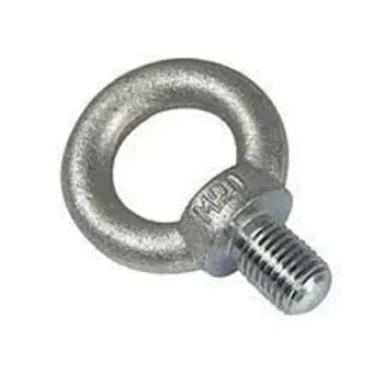
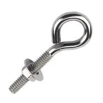
Eye bolts are used for the transporting of the tool, using lift hooks, and forklift holes will also be provided in some cases for transporting purposes. For example, we usually use M20 bolts that are bolted on the base plate.
When installing lifting eye bolts it is critical to ensure the face is in firm contact with the mating surface. These lifting rings are intended for linear pulling loads in the direction of the thread.
They are not intended for use where the load is perpendicular to the thread. This is because in these instances the bolt could unscrew and move or it could be twisted and break
6. Floor Plate:
The floor plate is grouted to the floor with a fixed bolt on the ground. Floor plates are also called foundation plates.
There will be a clearance of 10 mm maintained between the pedestal base plate & floor plate.
This clearance will be used by the leveling screws, for leveling the entire tool.
Weld bars are used to weld the positions permanently after leveling is done.
A weld bar is a plate along the sides of the base plate of the pedestal.
1. Working Height:
It depends on the nature of the manual or robotic welding fixture.
For manual fixtures, a working height of 850-1100 mm needs to be considered, depending upon the working height of the worker standard of a specific country. (In a few countries human height is higher or lower e.g., the US, and Japan).
If the base structure is made with a base plate having a tubular structure welded below it then we can reach to height of 100 mm to ~250 mm. In this case to reach the working welding height we need to provide additional leg structure which may have the top and plate welded to the tube.
Try to study the gun ergonomics properly then design the unit height and then base top height.
2. Base Plate or Welded Structure:
Depending upon the component size and weight of the total units we can decide whether we need a fabricated base or just a plate.
Mostly fabricated bases are made of square or rectangular tubes with plates.
3. Selection of Eye Bolt:
As a designer, it is important to know how a big base plate or bigger base welded structure will be handled during the fabrication and handling process.
Depending upon the weight eye bolt size is selected for lifting holes on the base plate.
Generally, 4 eye bolt provision is made. We also need to select the location of the eye bolt considering the rope/ belts used while shifting the structure or complete fixture are not damaging any units (rest, clamp, or location units) nearby.
4. Number of Measuring Holes Required:
We would need 3 holes to define the plane.
Most of the OEMs make 4 dowel holes at 4 corners and put small aluminum plates marking the X, Y &Z coordinates of dowel holes.
If the base length is too long few OEMs follow the methodology of having dowel holes at a 500mm distance.
5. Base Plate:
There are few OEMs, Line builders use only thick base plates. Few OEMs recommend a thick base plate of 40mm or 50mm for the child part assemblies (e.g. BMW). 40/50mm plate makes a very heavy structure but some OEMs follow the methodology.
If we go for a higher thickness it will not bend after machining and will have good flatness.
The general observation is if we go for a 10-12 mm thick plate for a large size e.g. 2mx2m, after machining when we unclamp the plate from the milling machine the plate will not show good flatness.
Fundamentals of base plate design:
A base plate size should cover all the units with its outer periphery including the opening.
A base plate is preferred to be designed concerning BCS coordinates.
A base plate should be drilled with datum holes/ measuring holes in line with a pitch of 100mm in general.
The number of datum holes depends on the size of the base plate.
Datum holes should be drilled at nominal values of coordinates and in terms of 50 and 100.
Datum holes should be drilled with a diameter 100mm away from other units.
Datum holes should be covered with cover plates.
Dump Unit:
The dump unit is used when we have any constraints and we cannot use our normal units like clamp unit and pin unit etc. In such cases, to fix them, we use a dump unit. A dump unit can have more than one cylinder to perform such an operation. The first cylinder dumps the assembly carrying clamp mylars, and pins, and then this assembly performs the required operation. In this unit, we should make sure that in the open position of the panel, we should be able to remove the panel.
A dump unit can have a slide cylinder or a clamp cylinder attached to it. Cylinder validation is important in the case of a dump unit as the weight can be too heavy for the cylinder to dump. In such a case, calculations are done and the force exerted by the cylinder is checked against the weight of the load being carried. If the cylinder force is greater, it is validated or we use a more powerful cylinder.
Functions of the dump unit:
To ensure proper resting of the panel being welded and to restrict its motion.
To ensure there is no rotation in the panel and to fix it either by pins side blocks or magnets.
To ensure there is enough clamping force in the cylinder so that it doesn't move while welding.
The dump unit should have correct shimming for adjustment of the panel.
The dump unit is a complex unit. The design of the dump unit must be done with almost care and preciously.
The clamp unit and pin unit which are designed in the Dump unit have to be checked whether the clamp and pin positions are correct. There should be no interference between the parts. All the parts in the dump unit must be independent.
The assembly of the Dump unit should be lightweight. At the same time must be hard enough to carry the panel with constraints in all DOF This is due to the lesser the weight, the lesser the force required to push and pull the assembly. Here, we apply material such as aluminum on the cylinder and steel on the rest of the parts to calculate the mass of the moving assembly. We take mass a bit more than calculated for the factor of safety.
The time of opening and closing of the clamp should be the least possible and this will depend on the power of the cylinder and the weight of the assembly being dumped.
Cylinder validation is an important aspect of the dump unit or any clamp unit design because the cylinder should be able to push the load for operation and then pull it back after the operation is complete.
Check the open condition after the cylinder validation because the panel should not coincide with the unit while removing.
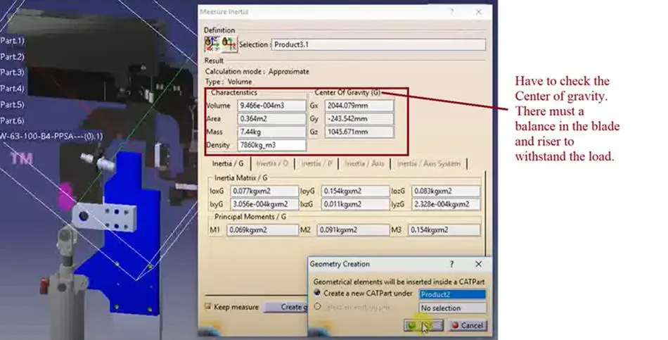
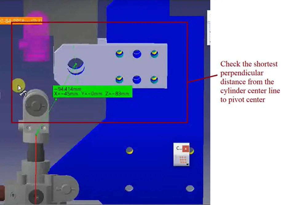
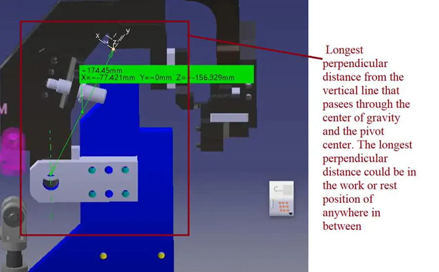

Slide units are positioning units that are used to position the car part, fixture, and weld gun robots into position for further operations.
Slide units may be classified into two types based on the type of guideways used as hardened guideway and LM guideway.
Slide units may further be classified into three types based on the prime mover used as manual slides, Hydraulic/pneumatic slides, and CNC slides.
It may be further classified as Horizontal, Vertical, and Angular slide units depending on the application.
LM guides are preferred over the hardened guide ways due to the least coefficient of friction.
The slide unit essentially consists of LM guides, linear cylinder, front and rear stopper, front, and rear shock absorbers, two proximity switches/reed switches for sensing the two end positions, bellows, or protection covers for rails.
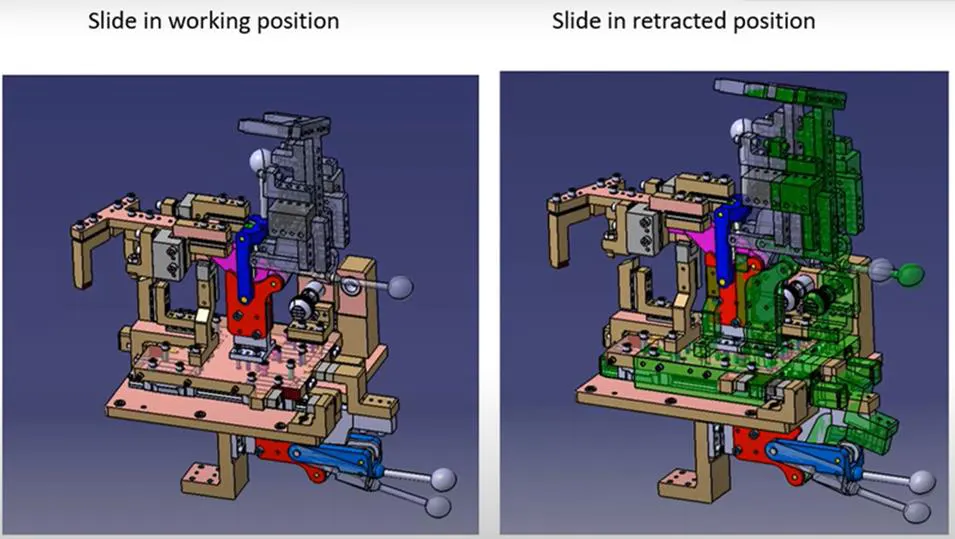
The 3D finish is a process where the design is brought finished and ready for final simulation &2D detailing
The following points need to be considered while finishing your design
Hole concentricity & Hole sizes should be checked to ensure that the parts are aligned properly or there are any mismatches with the assembly.
Machining area the surface that is to be machined should be represented with proper finishing and to represent the machining surface should be indicated any color
The nomilnality of the holes is checked which ensures the parts and base unit are aligned properly is there any interference between the unit and to unit? if there are any unwanted gaps or interferences we should adjust the spacings.
The hole coloring standard for the fasteners and dowel holes should be some standard colors. Clearance holes are aqua_blue color and threaded holes are Yellow color and Dovel Navy_blue color
Gaps Checking the gap between different units and assemblies and weld areas and other small parts need to be checked for proper assembly
Fasteners Implementation as per the hole sizes & the standard color codes and as per the customer requirements we need to finalize the holes whether it is a simple hole counterbore hole or threaded hole.
Avoiding clashes between different parts of every unit and parts having some gaps from panel to mylar or a pin and checking the Weld gun clearances for welding.
Mylar splitting as per panel profile if any mylar was located in an embossing or any curved or profile surface then the mylar must have the panel profile.
After completing all the above steps the model was sent to simulation and 2D detailing
Hole concentricity & Hole sizes
All the holes should be checked to ensure that the parts are aligned properly or there are any mismatches with the assembly. the fasteners and parts are in concentric clearance holes and threaded holes.
Machining area of the surface
which are to be machined should be represented with proper finishing and to represent the machining surface that should be indicated any color.
Nomilnality of the holes
The nominalality of the holes is checked which ensures the parts and base unit are aligned properly is there any interference between the unit to unit? if there are any unwanted gaps or interference we should adjust the spacings.
Hole coloring standard
The fasteners and dowel holes should be some standard colors. Clearance holes are aqua_blue color and threaded holes are Yellow color and Dovel Navy_blue color
Gaps Checking
The gap between different units and assemblies weld areas and other small parts need to be checked for proper assembly
Fasteners Implementation
as per the hole sizes & the standard color codes and as per the customer's requirements we need to finalize the holes whether it is a simple hole counterbore hole or threaded hole.
Pneumatic Layout
The pneumatic layout is collected of different pneumatic pipes which work as an inlet to the pneumatic cylinder .it should be done proper function of the unit
Avoiding clashes between different parts
every unit and part has some gaps from the panel to the mylar or a pin for checking the Weld gun clearances for welding.
Mylars splitting as per panel profile
if any mylar was located in an embossing or any curved or profile surface then the mylar must have the panel profile.
Proper renaming of parts/assemblies as per standard:
Proper renaming of parts and assembly should be done while finishing the design so that every person can understand the design.
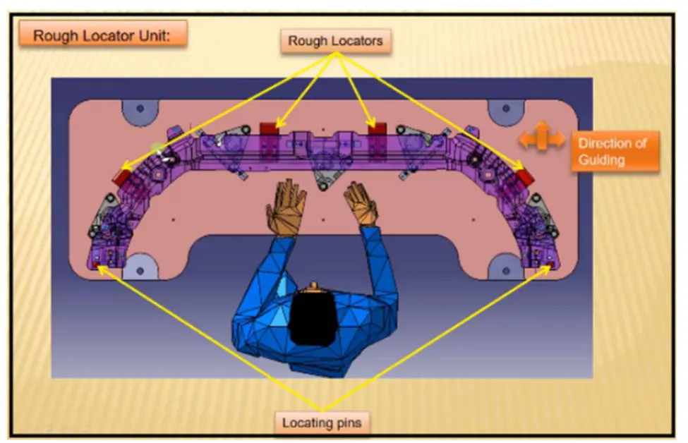
Rough locators are used and designed to guide the operator to locate the panel in the exact location before entering the pin .it can be a standard part of a self-designed part
Uses of Rough Locator
Rough locators are used to locate workpieces in a BIW fixturing process. to place the panel into an exact location.
The accuracy of the locating components directly affects the consistency and how the final product will come out. this is why these components are essential to the panel setup.
Rough locators are used where manual loading of panels is implemented on the fixture.
These are used to guide the panels in the correct position and orientation
Rough locators must never touch the parts when it is nested or controlled by the primary tool locator.
If not required to finish cold /hot rolled steel for rough locators mounted use NAAMS standard rough locators when possible
A rough locator should have minimal parts in contact so that the operations can load the parts to the work location with ease. excessive parts contact may cause difficult parts loading and unloading
It can be called as Fool Proofing method also because due to rough locators, the parts can not be loaded incorrect position. the rough locators are set according to the angle of the respective panel hence parts can only be loaded in direction and orientation.
The following points need to be considered while designing the rough locators
A rough locator should be placed at the edges of the panel which has to guide the panel.
A rough locator has to be placed at the same angle as the car parts edge with a minimum of 2-5mm from the edge of the panel.
A rough locator should arrest the direction of the panel. and the guiding should start 10-15mm before the pin engagement
The rough locater should be designed with an entry angle for the panel and the rough locator should have two slots to mount for easy adjustments
The height of the locator should not be more than the permissible ergo height of the fixture
The entry point of the locator should be 10mm to 15 mm above the panel surface and the angle ranges from 30 -45 degrees
A rough locator cab is a rod-type or flat type. depends upon the standard based on the requirement
In the automotive industry, car panels are predominantly joined by various welding processes. A weld study is performed on the panel to be welded later which includes the required weld spots on the panel. These weld spots are taken into consideration while designing the fixture. Once the design of the fixture is completed, the weld gun that we intend to use in the actual process is put into the software, and the feasibility of the process is checked. This process of inserting the weld gun in the fixture design to check if the position of any part needs to be modified is called the gun study
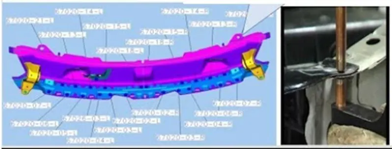
Fig weld study(spot locations)
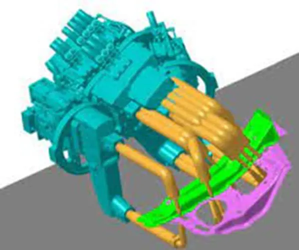
Fig weld gun
Welding is mostly used in automobile industries and their requirement for fixtures that ease the welding process is a continuous development task in any industry. In the weld study process, the major procedure insert the gun in the tool assembly and place the gun on the weld spots by creating a point on the tip, adjusting the weld gun so as not to get any clashes from the 3D concept. Once all the weld spots are cleared without any clashes they will be moved on to the next procedure of simulation.
In the simulation, first, we have to check the reach concerning the weld spots because robots also have some limitations if it exceeds the robot will not work 100 percent. So first we moved with the reach check and then tried to adjust the weld gun concerning the 3D concept design, if any clashes arise in the simulation, we will get cleared with CATIA software.
Car body in white (BIW) is a complicated steel structure including 300-500 sheets with complex shapes and are assembled using welding in a high rhythm through 55-75 robotic workstations. The foremost step taken before starting the welding fixture design, we must declare the weld spot location for every panel.
The location and orientation of other critical units of the fixture including clamps, location, etc are decided based on the weld spot distribution.
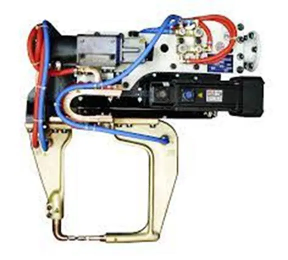

c-Type Gun X_Type gun
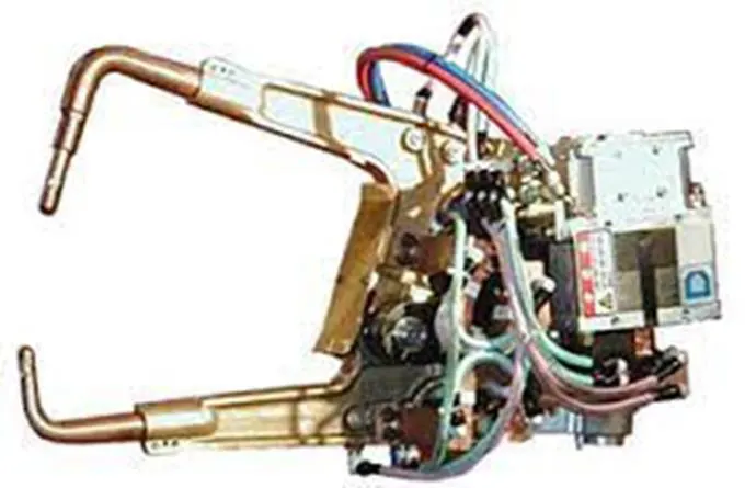
Scissor Type gun
Weld gun study is a very time-consuming process, the entire welding cycle time study depends on the number of spots and the weld gun study
These are a few points which we need to take care of when we perform the gun study
The axis of the weld spot along the welding direction must be normal to the weld
The gun study should be performed once before the actual simulation
The position of the gun should be manipulated first in case of a collision with other parts.
If the position of the gun cannot be manipulated further, the location of the part must be modified or it can also be modified depending on the situation The entire given weld points must be cleared.
During the gun study, we have to consider client cycle time and we have to maintain the cycle time compared to client requirements
There are two types of weld spots they are:
Geo-spot and respot have different timings
Geo-spot-3 sec.
Respot-2 sec.
If we have one or more device models and we want to program, the behavior of each model in the work cell can be simulated over time. Instruction for each device is coded by giving a sequence.
If we have no issue with the weld gun we have to move on to the next procedure to run the paths( pathways) to analyze if there is any clash while the weld gun reaches a weld spot then if we do that and finally move to the sequence of operation.
After sequencing all the devices and paths finally simulation is run with a collision check to make sure all the weld spots and paths are clear from a collision using safe robots.
IMAGES: