Week 2 Bevel Gear Challenge
Grid Dependency Test for the Bevel Gear Simulation
OBJECTIVE:
The main objective of this challenge is to perform a Grid Dependency Test fot the Bevel Gear with different element sizes like 6mm, 5mm and 4mm respectively. As well as to run the simulation and to compare the Von-mises stress, equivalent elasic strain and Total Deformation formed in between them.
SOFTWARE USED:
ANSYS Workbench 2021 R1 and ANSYS Mechanical for Analysis
INTRODUCTION:
Bevel gears are gears where the axes of the two shafts intersect and the tooth-bearing faces of the gears themselves are conically shaped. Bevel gears are most often mounted on shafts that are 90 degrees apart, but can be designed to work at other angles as well. The pitch surface of bevel gears is a cone.
Two important concepts in gearing are pitch surface and pitch angle. The pitch surface of a gear is the imaginary toothless surface that you would have by averaging out the peaks and valleys of the individual teeth. The pitch surface of an ordinary gear is the shape of a cylinder. The pitch angle of a gear is the angle between the face of the pitch surface and the axis.
The most familiar kinds of bevel gears have pitch angles of less than 90 degrees and therefore are cone-shaped. This type of bevel gear is called external because the gear teeth point outward. The pitch surfaces of meshed external bevel gears are coaxial with the gear shafts; the apexes of the two surfaces are at the point of intersection of the shaft axes.
The use of a genuine bevel gear has even greater importance for the reliability of the axle than any other spare part. Bevel gears that have pitch angles of greater than ninety degrees have teeth that point inward and are called internal bevel gears.
Bevel gears that have pitch angles of exactly 90 degrees have teeth that point outward parallel with the axis and resemble the points on a crown. That's why this type of bevel gear is called a crown gear.
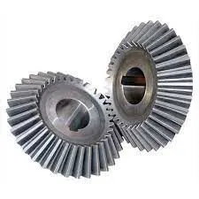
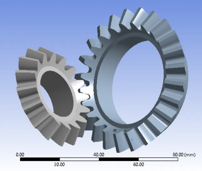
FIG 1: BEVEL GEAR MODEL
Detailed Explanation on Grid Dependency Test:
Grid Dependency Test is a test in which, the analysis begins with Coarse mesh and it is then refined to finer mesh, in order to find the optimal and higher accurate results for the given model. And also to know how the solutions well behave on grid sizes. Smaller the mesh size well give accurate results but it well leads to increase the computational time. So choosing the optimal mesh size will gives the correctl solution.
Uses: Provides optimal mesh size for the given model either too coarse mesh nor too fine mesh.
METHOD: The method (preprocessor) which we have followed for all the three cases (i.e mesh size of 6mm, 5mm, 4mm ) are same expect the changing of global mesh size as 6mm, 5mm and 4mm respectively. By keeping the face sizing as 1.75mm for all the cases. The below procedure shows the preprocessor of a bevel gear along with its results.
PROCEDURE:
To Perform a grid dependency test for the Bevel gear simulation for mesh sizes of 6,5 and 4 mm
1. Open the ANSYS Workbench software. Under the Analysis system select the Static structural and wait for few seconds to pop up the window, which contains Engineering data, Geometry, Model, setup, Solution and Results.
2. Rename the static structural as Bevel gear.
3. Under geometry import the Bevel gear model.
4. Update the model by right click and edit the Model for meshing.
5. Wait for few seconds and ANSYS Mechanical will open as shown below. Under geometry rename the gears as small gear and big gear.
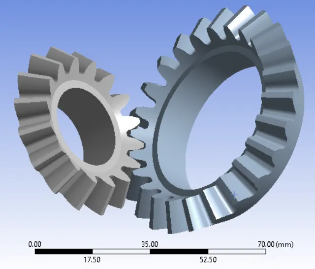
FIG 2: Bevel Gear Model
6. Assign the material to the model, as in our case we have structural steel, the material will asign automatically. If we need another material then we have to click on the model, which we have to assign the material. The below figure shows the material properties of a structural Steel.
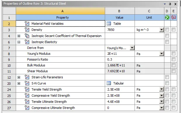
FIG 3: Material properties of a structural steel
7. Define the contacts in between the tooth of the spur gears. we can define the contact for whole model, but the time taken for simulation will be high. so the contact is given in between the tooth where it is neccesary.
Change type to frictional, with frictonal coefficient as zero, behavior to symmetric and formulation to augmented lagrange. Agmented lagrange will aviod the penentration of gears as well as scattering. The small gear will have 16 faces and big gear will have 24 faces respectively.
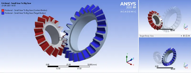
FIG 4: Contact between the Gears with Zero frictional coefficient
8. Insert a revolute joints for the gear in order to revolute about their axes. So click on connections go to insert and select joint. select body to ground option, type as revolute and select the inner face of the gear for reference. Follow the same method for another gear.
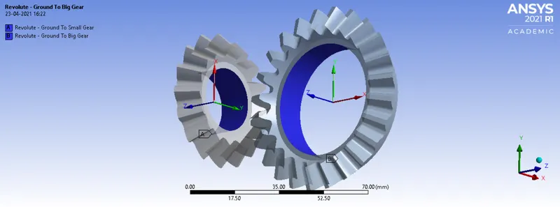
FIG 5: Applying revolute joint about their axes
9. In ANSYS automatic mesh will be performed with Default mesh size and change the mesh size as 6mm, 5mm, 4mm respectively. Perform the simulations separately for the Global mesh size as 6mm, 5mm, 4mm respectively, in order to see the simulations at different mesh sizes.
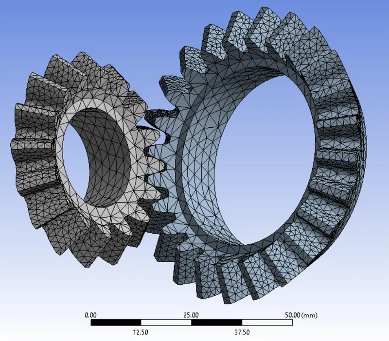
FIG 6: Model with global meshing
Be aware of ANSYS Student Edition and don't go beyond the size limit. The below figure shows the mesh size along with its number of nodes and elements.
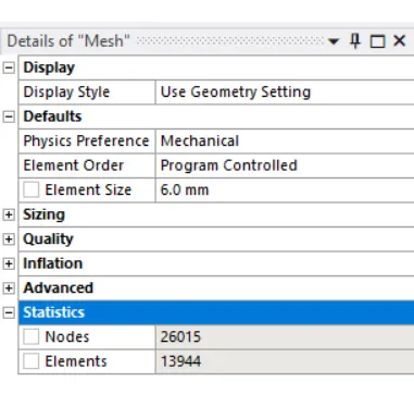
FIG 7: Bevel Gear with element size as 6mm
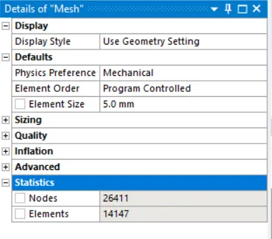
FIG 8: Bevel Gear with element size as 5mm
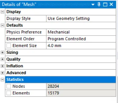
FIG 9: Bevel Gear with element size as 4mm
Actually we are looking for the stress and strain generation at the tooth of the bevel gear. For accurate result as well as for reducing the simulation time we are assigning face mesh at the tooth faces with the face value of 1.75mm.
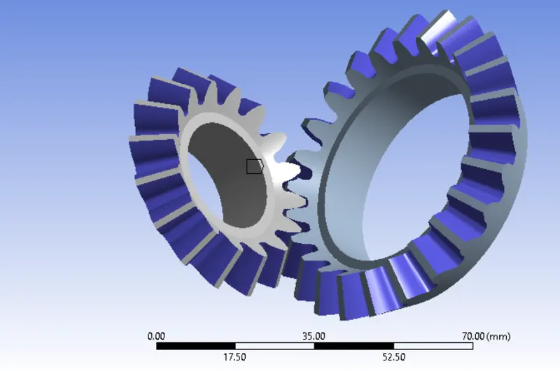
FIG 10: Selecting the tooth for face sizing
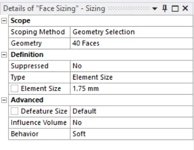
FIG 11: Bevel Gear with Face size as 1.75mm
10. As it is a solid structure we have to change the 2D Element to 3D Element. So click on mesh and select the insert option. Under insert option select the method and slect the gemetry as well as under the method, select the tetrahedrons.
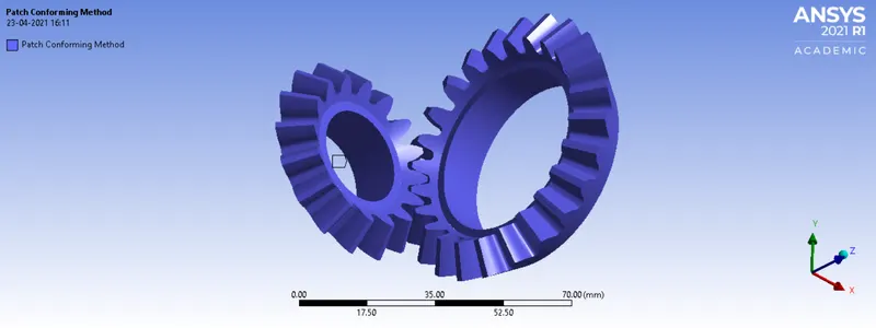
FIG 12: Selecting Bodies for 3D Meshing
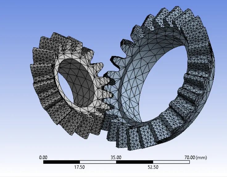
FIG 13: 3D Meshing
11. Analysis settings Change no. of steps as 6, auto time steeping on, define by time, carry over time step as off, intial time step as 0.2s, minimum time step as 5.e-004s, maximum time step as 0.5s.
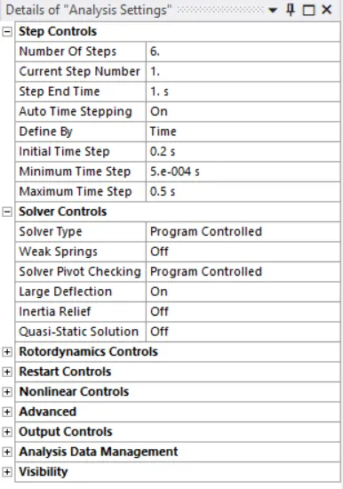
FIG 14: Analysis settings
12. Now define the joint load for both the gears. so click on the static structural and select joint load, change the type as rotation for small gear and assign the rotational value in the table from 0, 20, 40, 60, 80, 100, 120. Then similarly insert the joint load and change the type to moment for Big gear and assign the moment as 100Nmm.
The moment of 100Nmm is given to the Big Gear through out the process and the rotational joint is given to the small Gear of 120degree and have a increment of 20degree at each step. (6 steps)
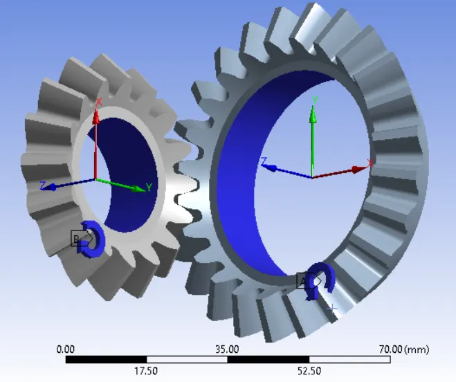
FIG 15: Applying joint loads, for small gear - Rotation and Big gear- Moment
13. Now request for the outputs such as equivalent stress, equivalent elastic strain, total deformation.
14. SOLVE the solution and we can see the simulation run under soluion information.
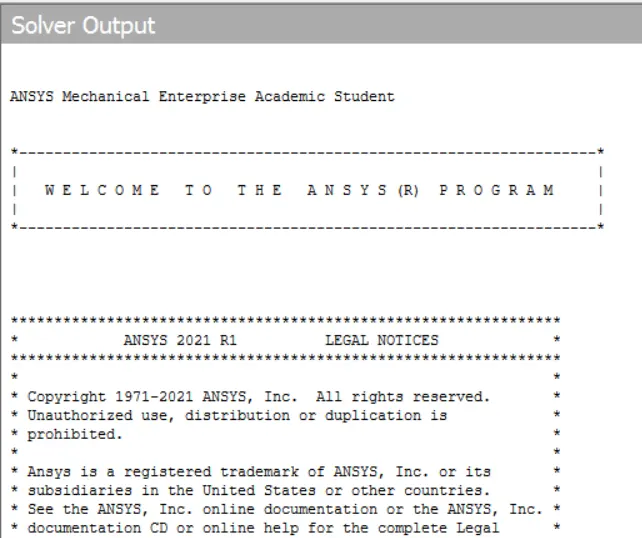
FIG 16: Solver output
The output requests are:
Simulation results for different mesh sizes are shown below
CASE-1 MESH SIZE OF 6mm
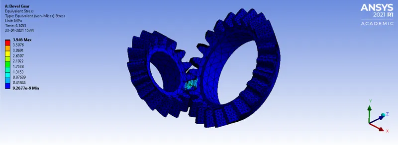
FIG 17: Von-Mises Stress for a Mesh Size of 6mm
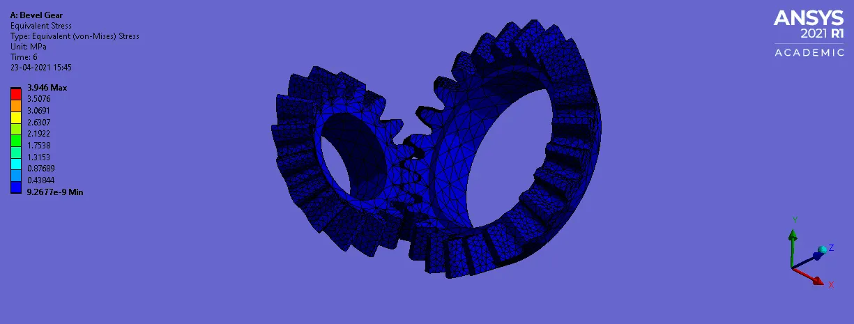
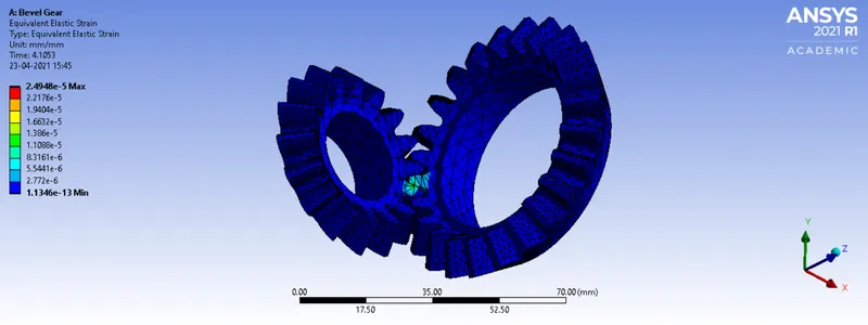
FIG 18: Equivalent Elatic Strain for a Mesh Size of 6mm
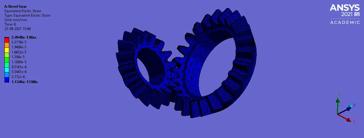
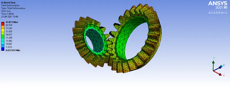
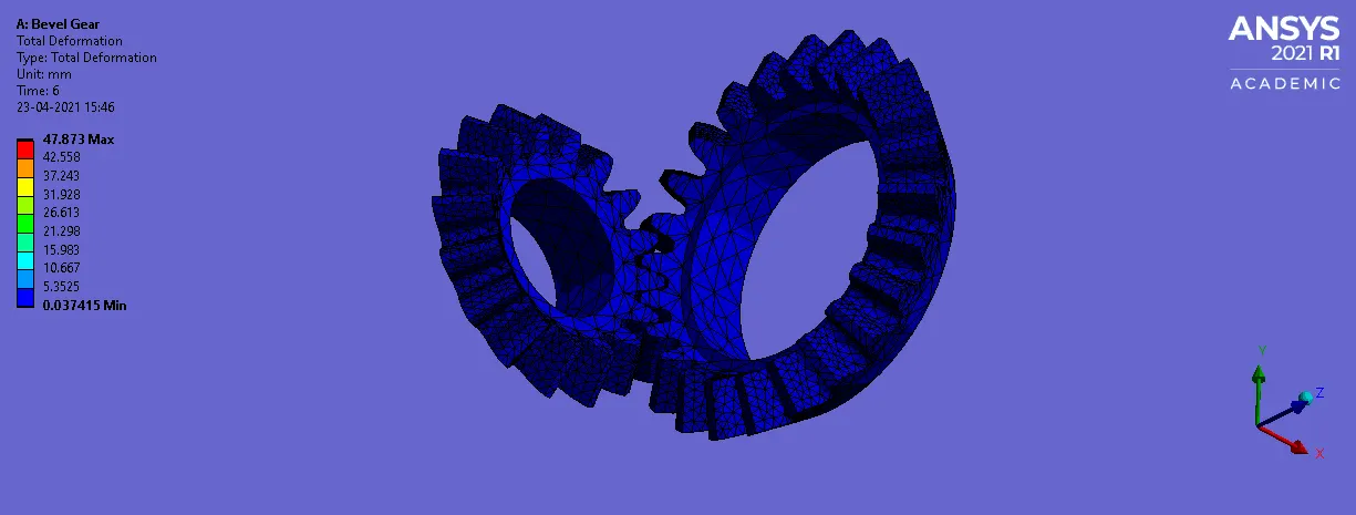
FIG 19: Total Deformation for a Mesh Size of 6mm
CASE-2 MESH SIZE OF 5mm
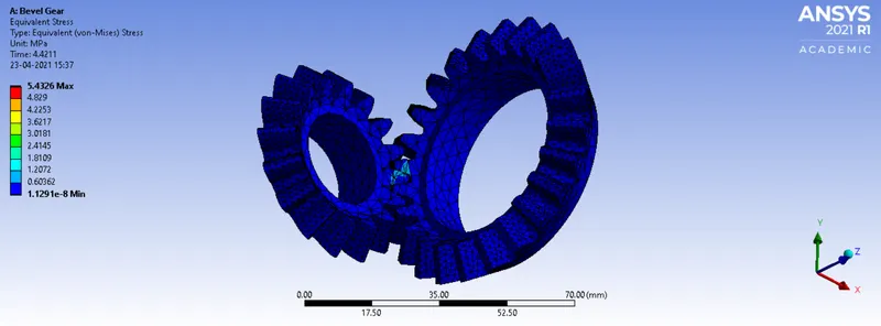
FIG 20: Von-Mises Stress for a Mesh Size of 5mm
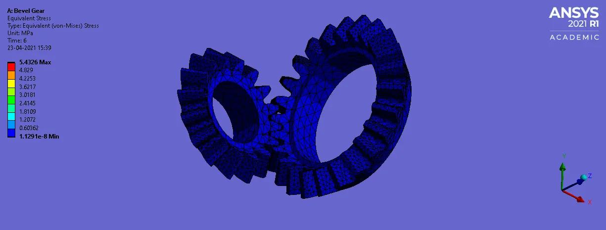
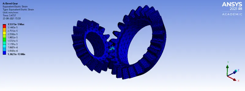
FIG 21: Equivalent Elatic Strain for a Mesh Size of 5mm
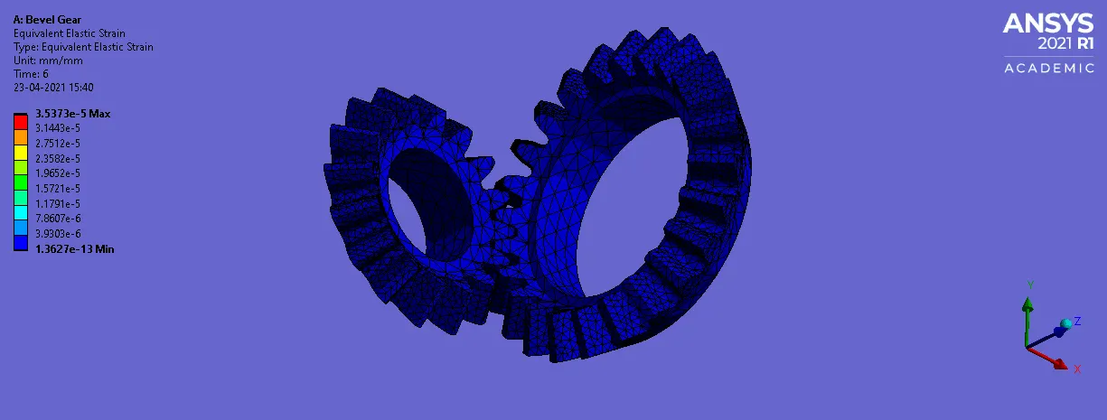
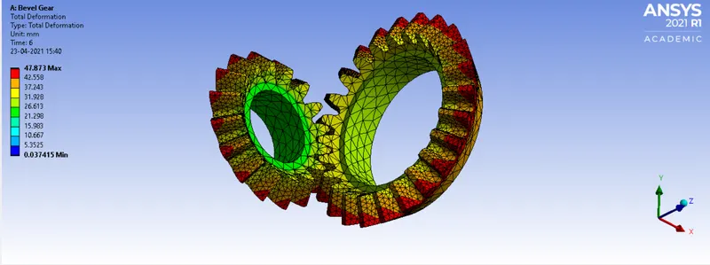
FIG 22: Total Deformation for a Mesh Size of 5mm
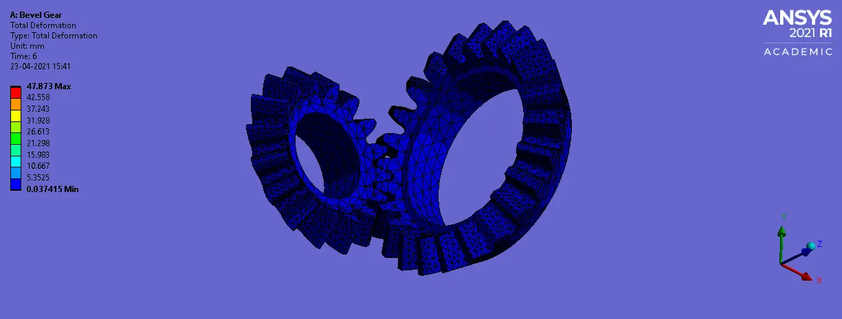
CASE-3 MESH SIZE OF 4mm
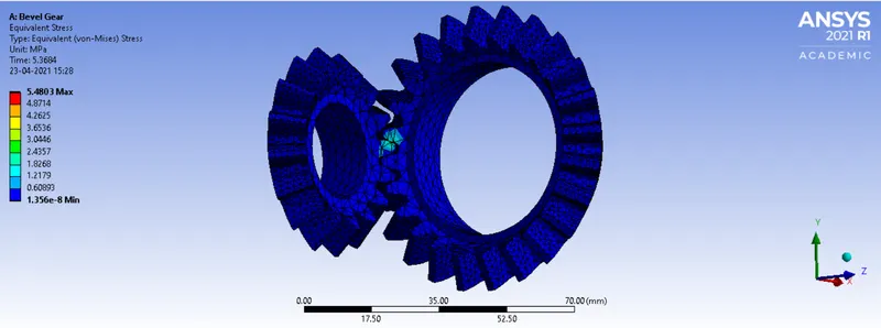
FIG 23: Von-Mises Stress for a Mesh Size of 4mm
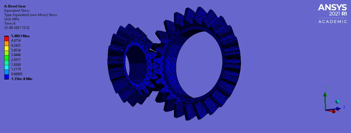
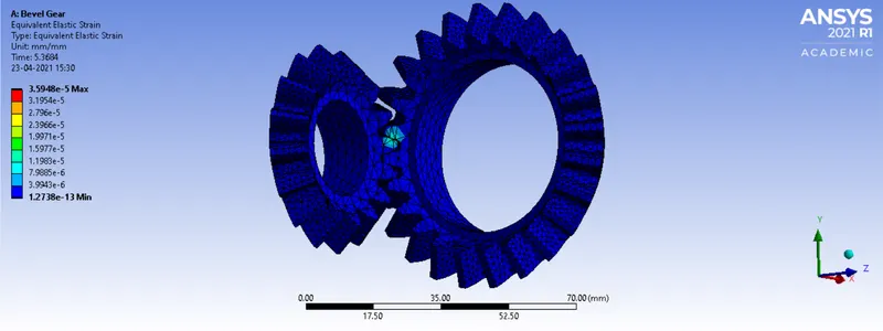
FIG 24: Equivalent Elatic Strain for a Mesh Size of 4mm
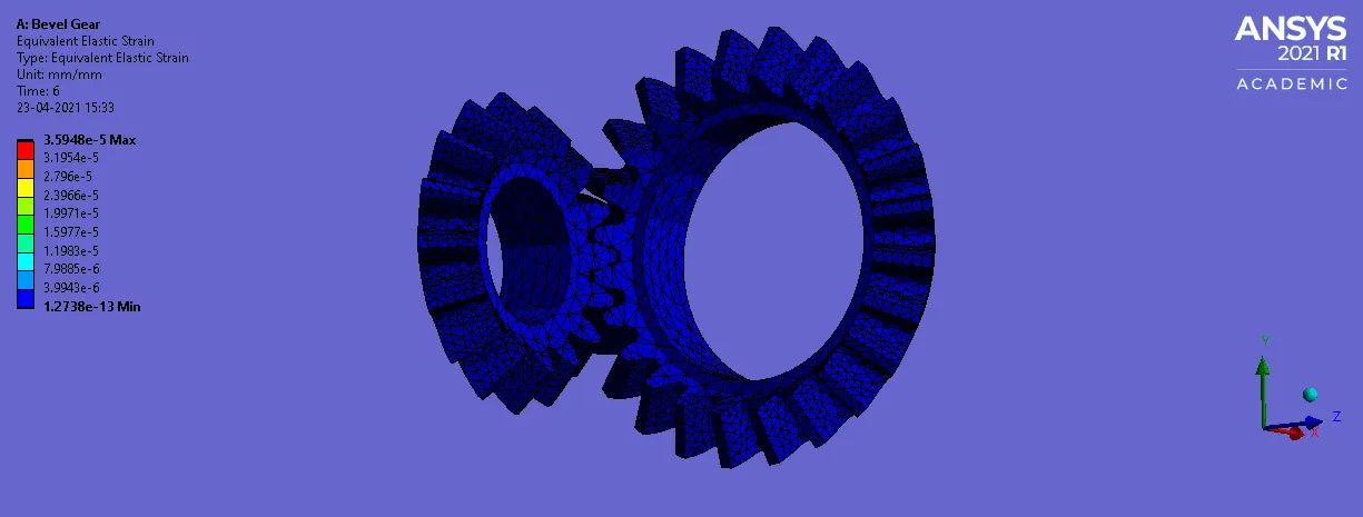
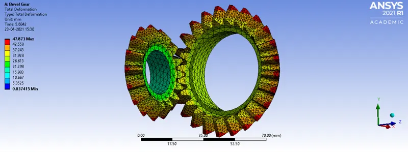
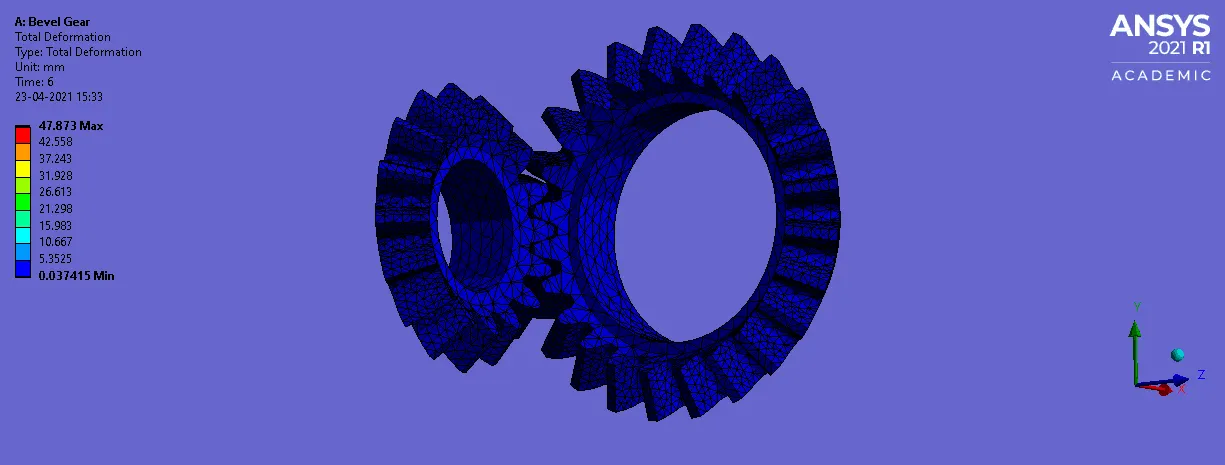
FIG 25: Total Deformation for a Mesh Size of 4mm
RESULTS
COMPARISM OF ALL THREE CASES RESULT:
| Cases | Element Size |
MAX EQUIVALENT STRESS (MPa) |
MAX EQUIVALENT ELASTIC STRAIN |
TOTAL DEFORMATION (mm) |
| 1 | 6 | 3.946 | 2.4948e-5 | 47.873 |
| 2 | 5 | 5.4326 | 3.5373e-5 | 47.873 |
| 3 | 4 | 5.4803 | 3.5948e-5 | 47.873 |
CONCLUSION:
The Grid dependency test has been performed and the maximum equivalent stress, maximun equivalent elastic strain and total deformation has been tabulated. From the above table it is clear that the by decreasing the element size value, the stress and the strain are increased, this is due to that by increasing no. of elements, the interal element deformation will be more. Since the strain is calculated by interal deformation, if the deformation is more strain will be more, if strain will be more the stress will be more. This the reason for increasing the stress and strain value. The element size 5 and 4mm will have closer value as well as it will be the accurate value, when compared with 6mm size. By further decreasing the element size will give accurate value, but with very close approximation value. This will increase the simulation time as well as the cost of project will be more. The Total Deformation remains constant for all the cases.
LINK: https://drive.google.com/drive/folders/1zEkQnCtfnJ3b6N8MEo79naY271IjjuOh?usp=sharing