Week 10 Bullet penetrating a Bucket Challenge
Bullet penetrating a Bucket
OBJECTIVE: The main objective of this challenge is to perform explicit dynamic analysis of a Bullet penetrating a Bucket and to simulate a bullet penetrating into a bucket by using 3 different non linear materials for the bucket and to analyse their behaviour for the same velocity of bullet. We have to apply the conditions for bullet as mentioned in the video and to analyse the total deformation and Equivalent stresses acting on the model.
SOFTWARE USED: ANSYS Workbench 2021 R1 and ANSYS Mechanical for Analysis.
INTRODUCTION:
The CAD Model of Bullet penetrating a Bucket is shown in below figure. The model consists of a bullet and a bucket. The behaviour of three different material is analysed by using same velocity for all materials and the material is analysed by striking of bullet into the bucket. The bucket is divided into two parts where the bullet strikes the bucket.
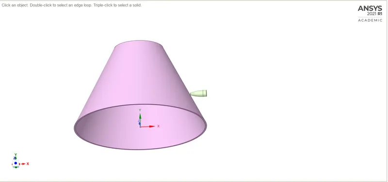
FIG.1: CAD MODEL
PROCEDURE:
CASE-1 ALUMINUM ALLOY NL
1. Open the ANSYS Workbench software. Under the Analysis system select the Explicit Dynamics and wait for few seconds to pop up the window, which contains Engineering data, Geometry, Model, setup, Solution and Results.
2. Rename the Explicit Dynamics as Bullet penetrating a Bucket.
3. Under geometry import the Bullet penetrating a Bucket model.
4. Update the model by right click and edit the Model for Preprocessing.
5. Wait for few seconds and ANSYS Mechanical will open as shown below. Rename the model as Bullet and Bucket. Make the behaviour of the bullet as Rigid.
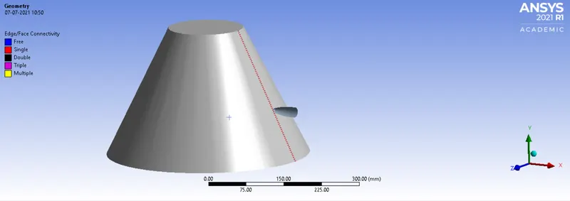
FIG.2: CAD model of Bullet penetrating a Bucket
6. Assign the material to the model. Right click on engineering data and under engineering data sources select explicit materials and assign tantalum to the bullet and under nonlinear material assign aluminum NL to the bucket.
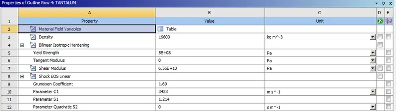
FIG 3: Material properties of a Tantalum
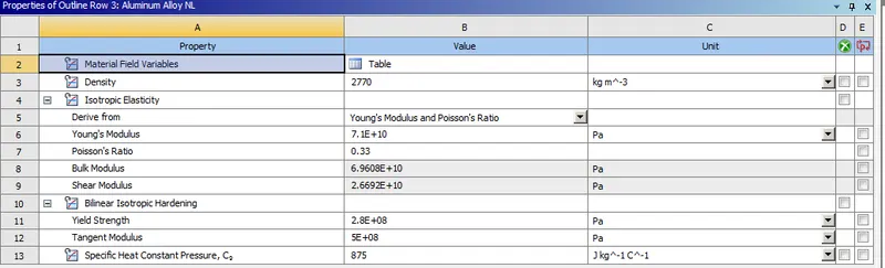
FIG 4: Material properties of an Aluminum alloy NL
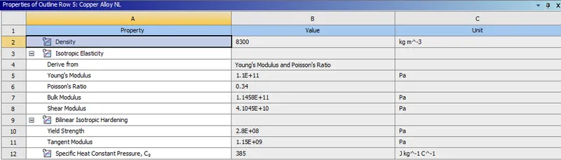
FIG 5: Material properties of a Copper alloy NL
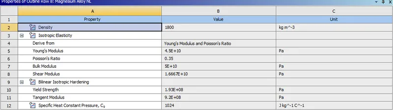
FIG 6: Material properties of a Magnesium alloy NL
7. Connections: Delete the default contact and under body interactions make sure that the type as frictionless.
8. In ANSYS automatic mesh will be performed with Default mesh size, so select the sizing option, select the egde option and select the edges as shown and assign a element size of 6mm.
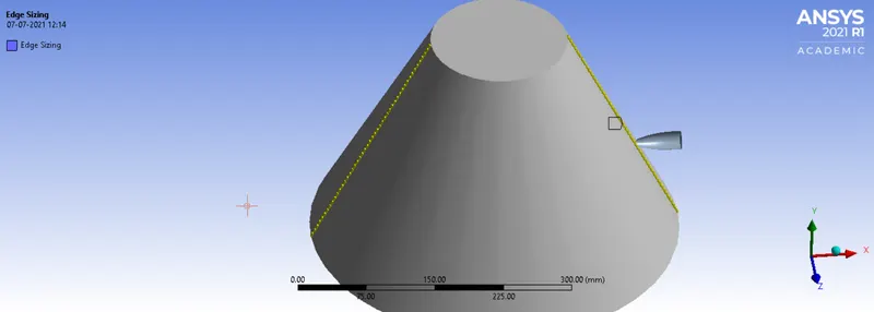
Fig.7: Edge selection for meshing
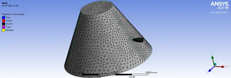
Fig.8: Meshing
9. Analysis settings: Provide the end time as 0.05s, maximum energy error as 2 and leave the rest of option as default.
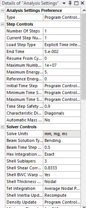
FIG 9: Analysis settings
10. Fixed support: Insert a fixed support to the bucket body and select the face as shown below.
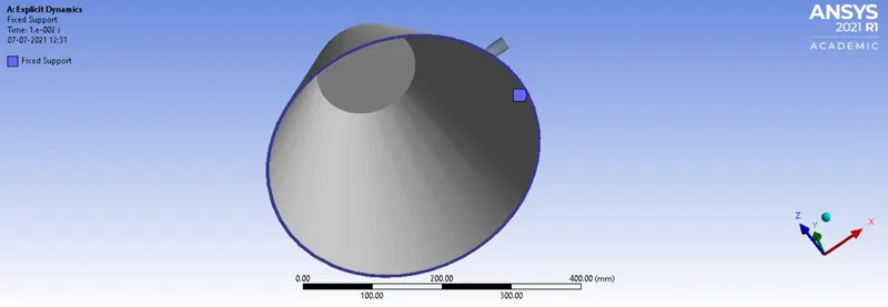
Fig.13: Fixed support
11. Velocity: Insert a velocity to the bullet body and select the body as shown below. Change define by components and select the X-direction and assign a value of -139000mm/s.
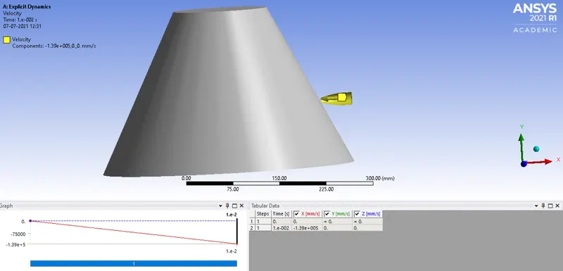
Fig.14: Velocity
12. Now request for the outputs such as equivalent stress, equivalent elastic strain and Total deformation.
13. SOLVE the solution and we can see the simulation run under soluion information.
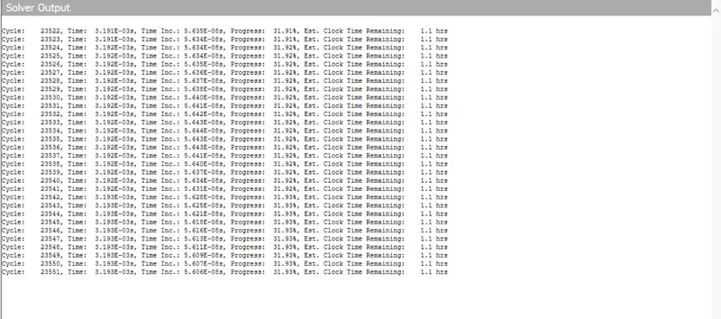
FIG.15: Solver output
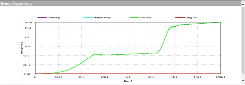
Fig.17 Energy Conservation
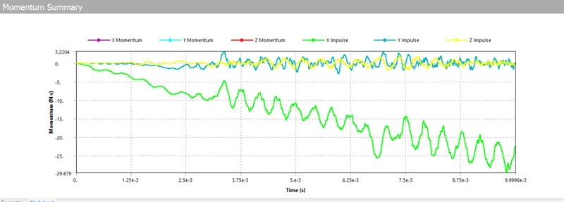
Fig.18 Momentum Summary
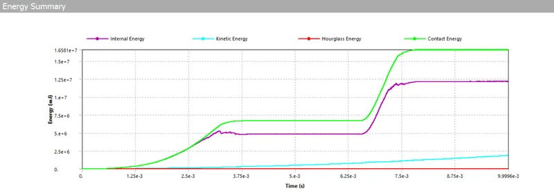
Fig.19: Energy Summary
CASE-2 COPPER ALLOY NL
1. Assign the material to the model. Right click on engineering data and under engineering data sources select explicit materials and assign tantalum to the bullet and under nonlinear material assign Copper NL to the bucket.
2. For remaining steps follow the same procedure as mentioned in Case-1 Aluminum alloy NL Material.
CASE-3 MAGNESIUM ALLOY NL
1. Assign the material to the model. Right click on engineering data and under engineering data sources select explicit materials and assign tantalum to the bullet and under nonlinear material assign Magnesium NL to the bucket.
2. For remaining steps follow the same procedure as mentioned in Case-1 Aluminum alloy NL Material.
SIMULATION RESULT:
CASE-1 ALUMINUM ALLOY NL
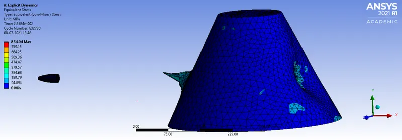
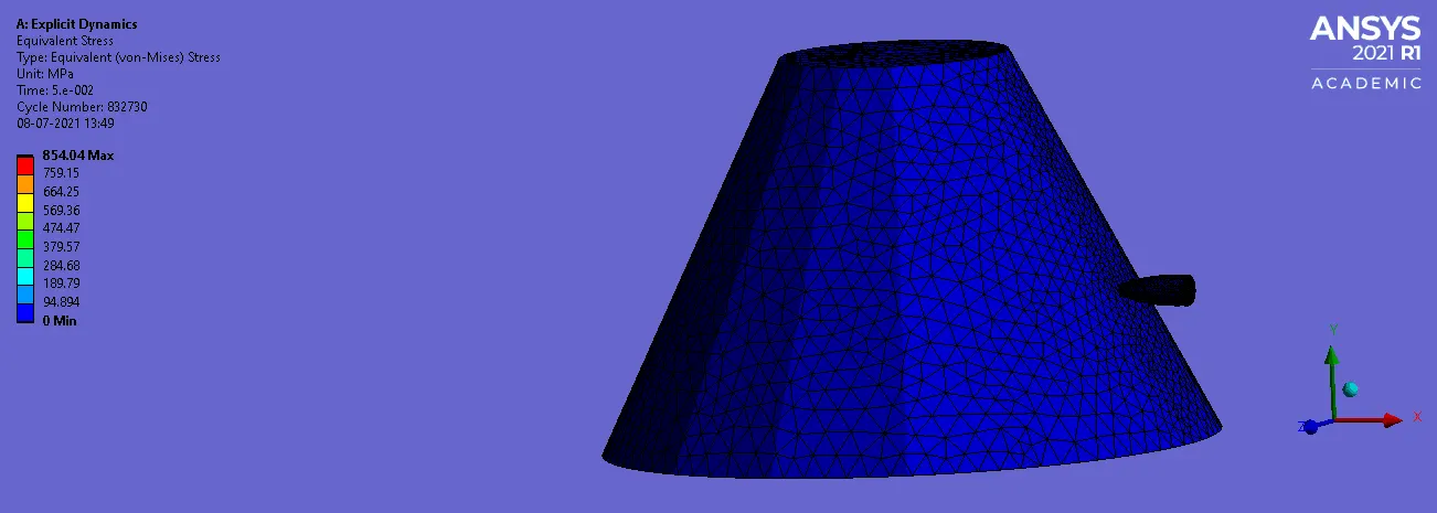
Fig 23: Equivalent Stress
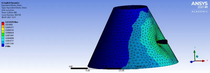
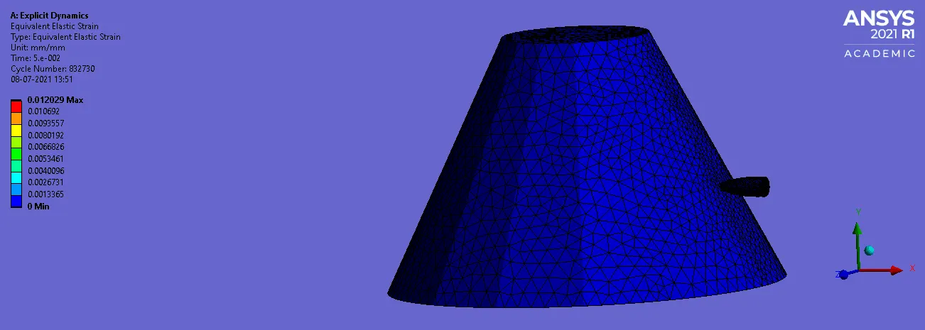
Fig 25: Equivalent Elastic Strain
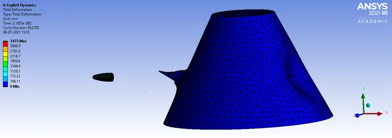
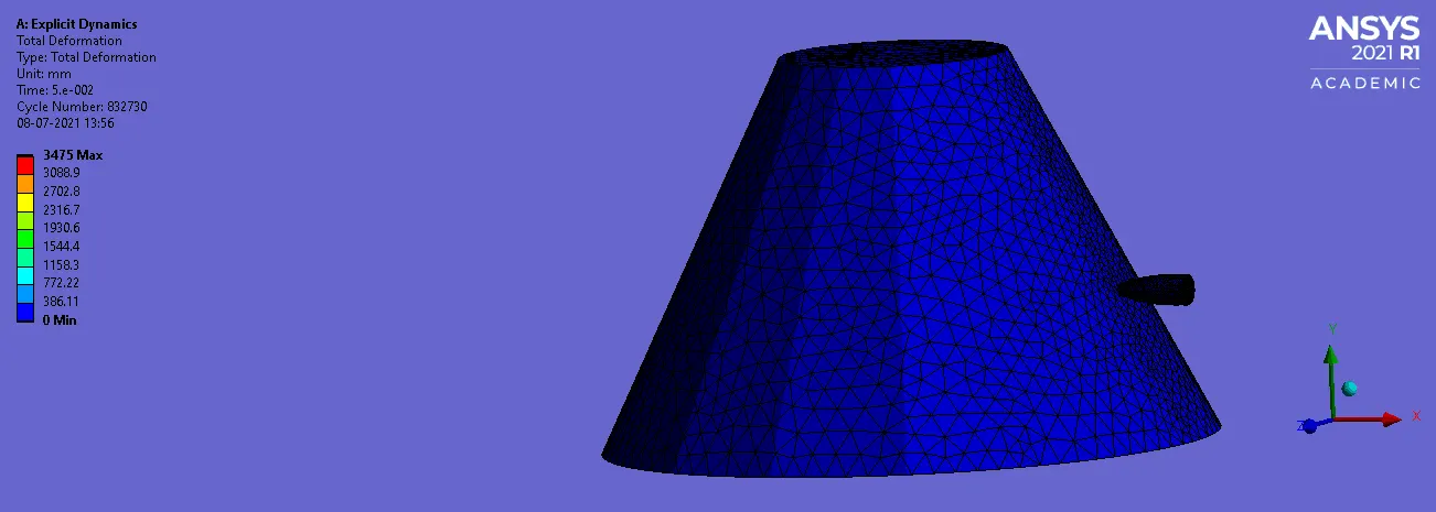
Fig 26: Total Deformation
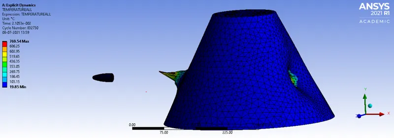
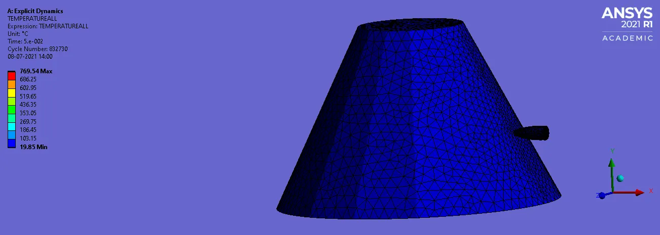
Fig 26: Temperature
CASE-2 COPPER ALLOY NL:
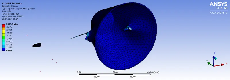
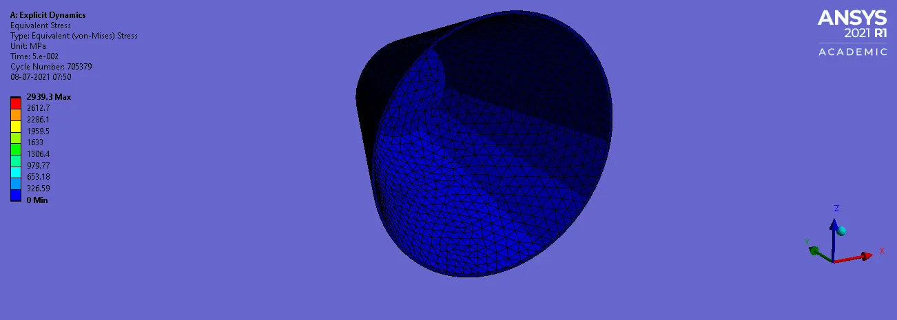
Fig 23: Equivalent Stress
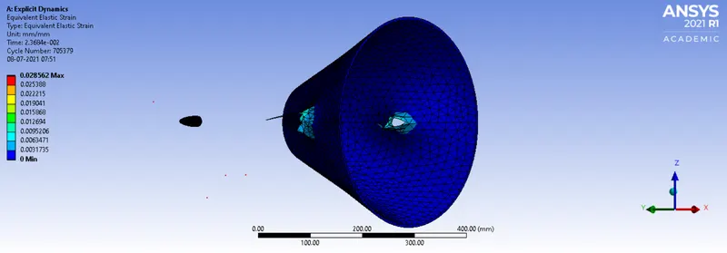
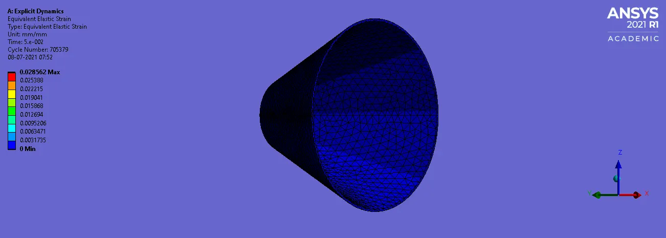
Fig 25: Equivalent Elastic Strain
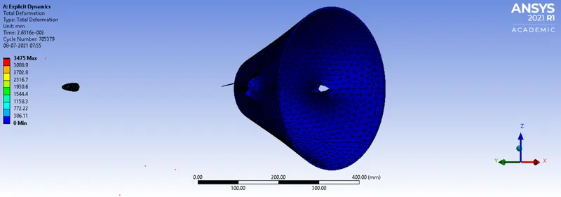
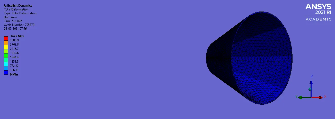
Fig 26: Total Deformation
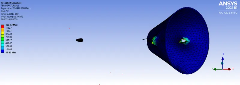
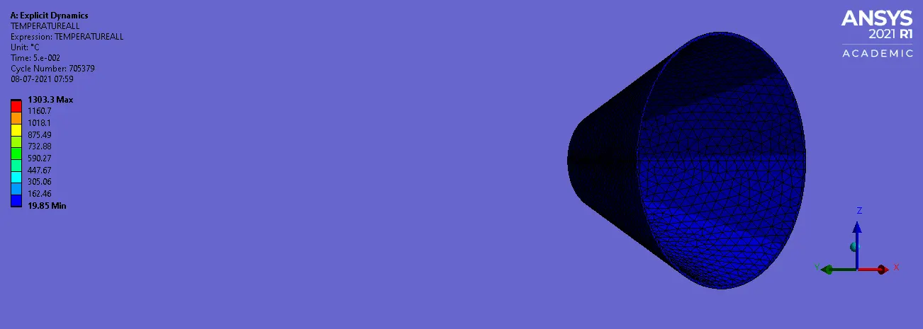
Fig 26: Temperature
CASE-3 MAGNESIUM ALLOY NL
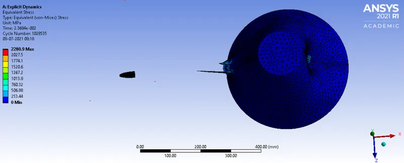
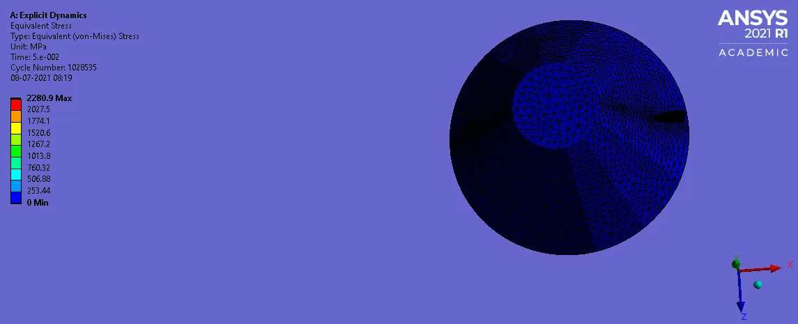
Fig 23: Equivalent Stress
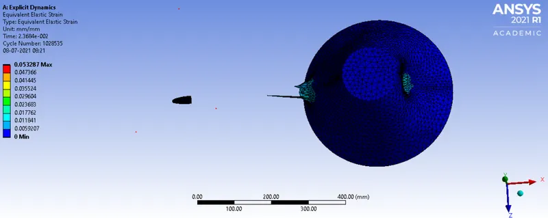
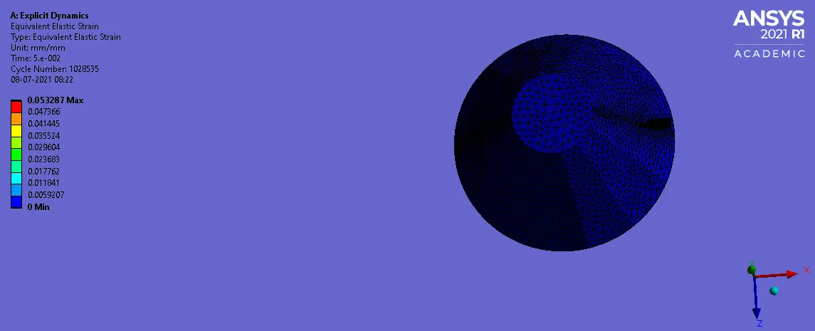
Fig 25: Equivalent Elastic Strain
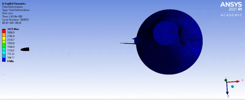
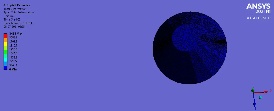
Fig 26: Total Deformation
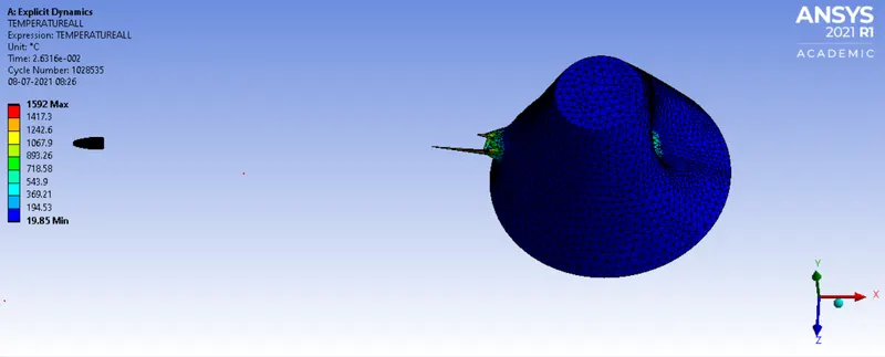
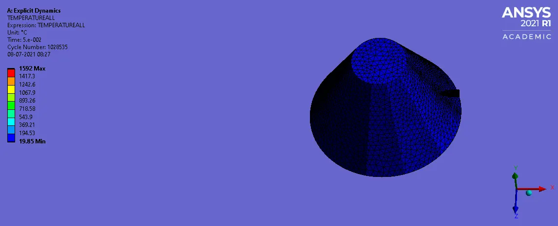
Fig 26: Temperature
Tabular results:
| CASES | MATERIAL | Equivalent Stress (MPa) | Equivalent Elastic Strain | Total Deformation (mm) | Temperature(°C) |
| 1. | ALUMINUM ALLOY NL |
Max:607.96 Min: 2.8818 |
Max: 8.5627e-003 Min: 0 |
Max: 3475 Min: 1.9816e-027 |
Max: 769.54 Min: 19.85 |
| 2. | COPPER ALLOY NL |
Max: 687.5 Min: 6.9869 |
Max: 1.0798e-002 Min: 0 |
Max: 3475 Min: 1.9816e-027 |
Max: 1303.3 Min: 19.85 |
| 3. | MAGNESIUM ALLOY NL |
Max: 662.56 Min: 5.9968 |
Max: 2.4702e-002 Min: 0 |
Max: 3475 Min: 1.9816e-027 |
Max: 1592 Min: 19.85 |
CONCLUSION:
From the above results we can conclude that the Highest equivalent stress of 687.5MPa is experienced, in copper alloy NL and Lowest equivalent stress of 607.96MPa is experienced in aluminum alloy NL, and a moderate equivalent stress of 662.56MPa is experienced in Magnesium alloy. Max Equivalent Elastic Strain of 8.5627e-003 is experienced in aluminum alloy NL, Max Equivalent Elastic Strain of 1.0798e-002 is experienced, in copper alloy NL and Max Equivalent Elastic Strain of 2.4702e-002 is experienced in Magnesium alloy.
The Max Total deformation of 3475mm is same in all cases and the Highest temperature of 1592°C is experienced, in Magnesium alloy NL, the Lowest temperature of 769.54°C is experienced in aluminum alloy NL and Moderate Temperature of 1303.3°C is experienced, in copper alloy NL.
Link: https://drive.google.com/drive/folders/1x_1kwgH2UqwkyAnjbSrw1UIdg-tBh_yh?usp=sharing