Week 4 -Wire Bending Challenge
Wire Bending Challenge
OBJECTIVE: The objective of this challenge is to perform a static structural analysis and to Simulate the bending of a wire in ANSYS. And we have to use Copper Alloy (Non Linear), Aluminium Alloy (Non Linear) and Magnesium Alloy ( Non Linear) for the wire alone. And we need to find out the Equivalent stress and Equivalent strain on the wire alone. As will as to compare the results.
SOFTWARE USED: ANSYS Workbench 2021 R1 and ANSYS Mechanical for Analysis.
INTRODUCTION:
Wire bending is the process of bending an wire to the certain angle and it is based on the requirements. Wire bending involves many type of bending as well as cutting. But in our challenge we have to know have a wire bent will experience different types of stresses and strains, when a wide variety of material is used to the wire. And also we campare the results in between them. The model here we used consists of Wire, Lever and Wheel.
Fig.1: Line diagram of wire bending
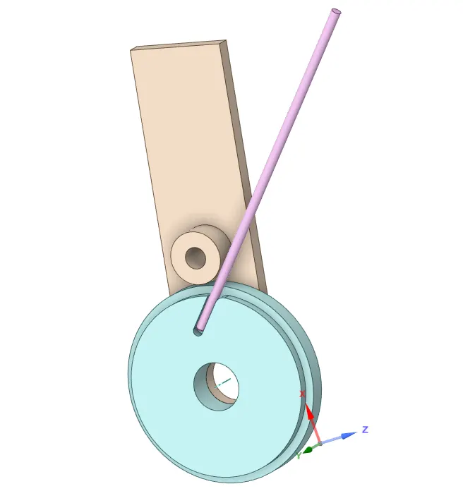
FIG.2: CAD MODEL
PROCEDURE:
1. Open the ANSYS Workbench software. Under the Analysis system select the Static structural and wait for few seconds to pop up the window, which contains Engineering data, Geometry, Model, setup, Solution and Results.
2. Rename the static structural as Wire Bending.
3. Under geometry import the Wire Bending model.
4. Update the model by right click and edit the Model for Preprocessing.
5. Wait for few seconds and ANSYS Mechanical will open as shown below. Rename the parts as Wire, Lever and Wheel.
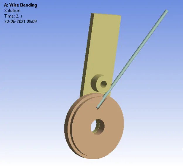
FIG.2: CAD Model of wire bending
6. Assign the material to the model, By classifying the required needs into three cases, And assign material to the model based on the cases.
Material used to the wire:
Case-1: Copper Alloy (Non Linear)
Case-2: Aluminium Alloy (Non Linear)
Case-3: Magnesium Alloy ( Non Linear)
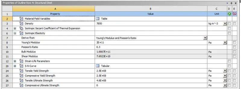
FIG 3: Material properties of a Structural Steel
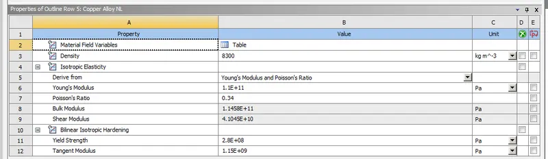
FIG 4: Material properties of a Copper Alloy
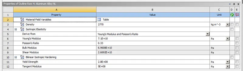
FIG 5: Material properties of a Aluminum Alloy
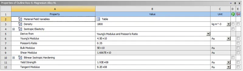
FIG 6: Material properties of a Magnesium Alloy
7.Contact between the parts
We have three default contact and delete first two contact and duplicate the third contact as well as flip the contact. Select the faces as showm below.
Frictional contact between the wire to lever and wheel to wire are Defined with a frictional coefficient of 0.2, formulation as augmented lagrange, normal stiffness factor as 0.1, update stiffness as each iteration, interface treatment as add offset ramped effects.
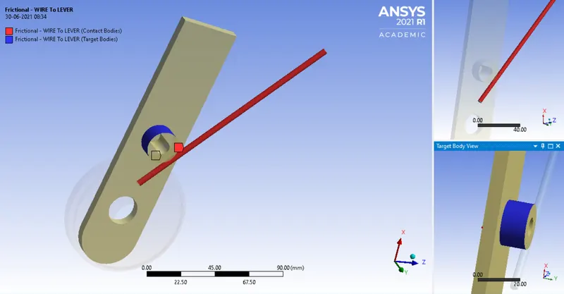
Fig 7: Frictional contact between the Wire to Lever
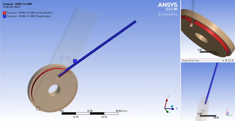
Fig 8: Frictional contact between the Wheel to wire
8. In ANSYS automatic mesh will be performed with Default mesh size and select the sizing option and select the wire and lever as shown below, assign the element size as 2.2mm. Similarly select the wire and element type as sphere of influence, assign the value of 0.8mm and radius as 7mm as shown below (i.e Ansys student version will have a limted number of elements and nodes.)
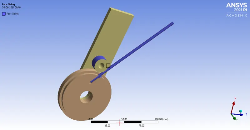
Fig.9: Selecting faces for meshing
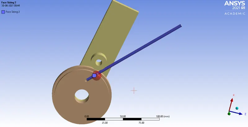
Fig.10: Selecting faces for meshing
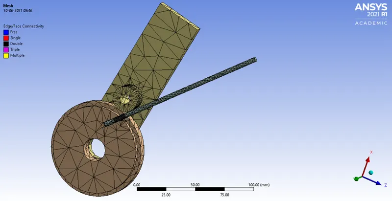
Fig.11: Meshing of wire bending
9. Analysis settings Change no. of steps as 8, for first step change auto time as on, large deflection on, Weak springs program controlled, solver type as Direct, define by time, initial time step as 0.1, minimum time step as 1e^-2, Maximum time step as 0.2, output controlls all as yes, select the time step 2-8 and change auto time as on, define by time, carry over time as on and minimum time step as 1e^-2 and maximum time step as 1.
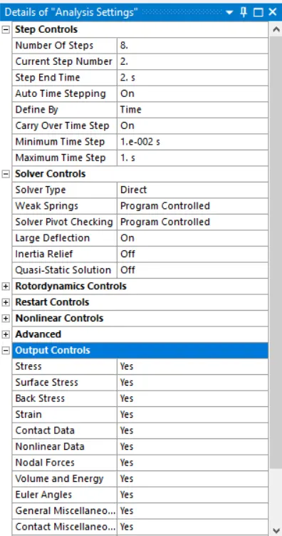
FIG 12: Analysis settings
10. Defining loads to the model.
a) Insert a fixed support and click the inner surface of wheel and fix it.
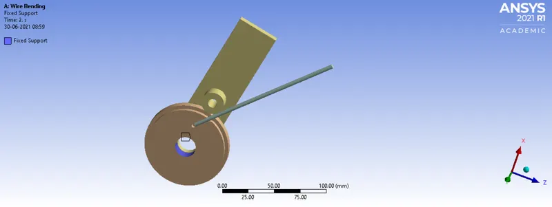
Fig.13: Fixed Support
b) Insert a fixed support and click the surface of wire as shown below and fix it.
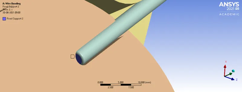
Fig.14: Fixed Support
c) Insert a revolute joint to the lever and select the face as shown below and change the type as revolute and connection type as body to ground. Make sure that the axis of rotation should be in Z-axis.
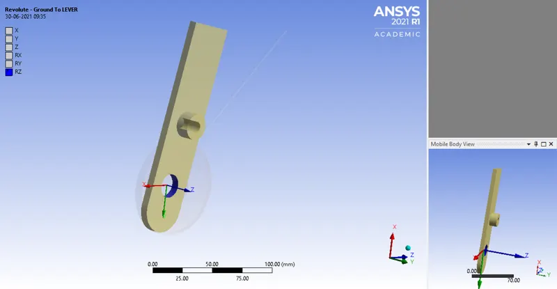
Fig.15: Revolute joint
d) Insert a joint load and select the revolute joint as rotation type, DOF as Z and a magnitude of 0,-20,-40,-60,-80,-100,-120,-140,-140.
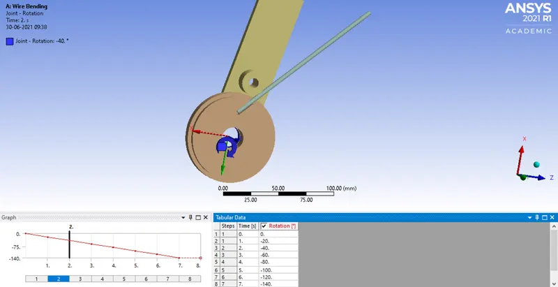
Fig.16: Joint Load
11. Now request for the outputs such as equivalent stress, equivalent elastic strain, Total deformation.
12. SOLVE the solution and we can see the simulation run under soluion information.
FIG 17: Solver output
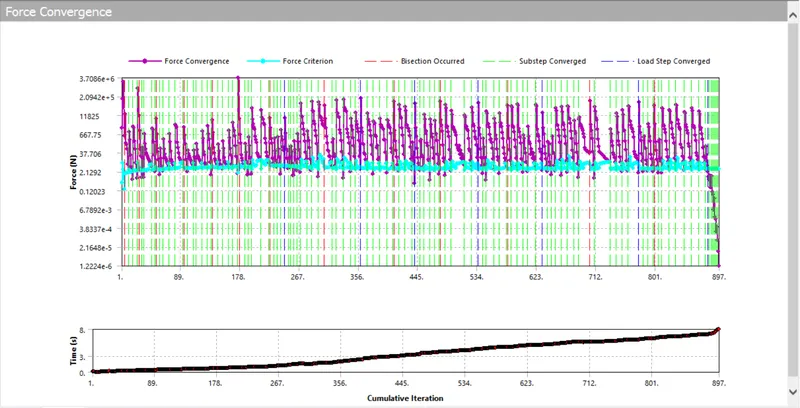
FIG.18 Force convergence
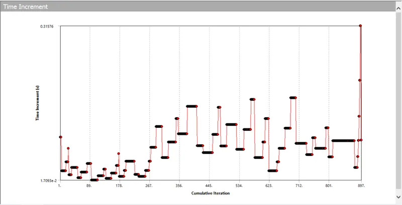
FIG.19 Time Increment
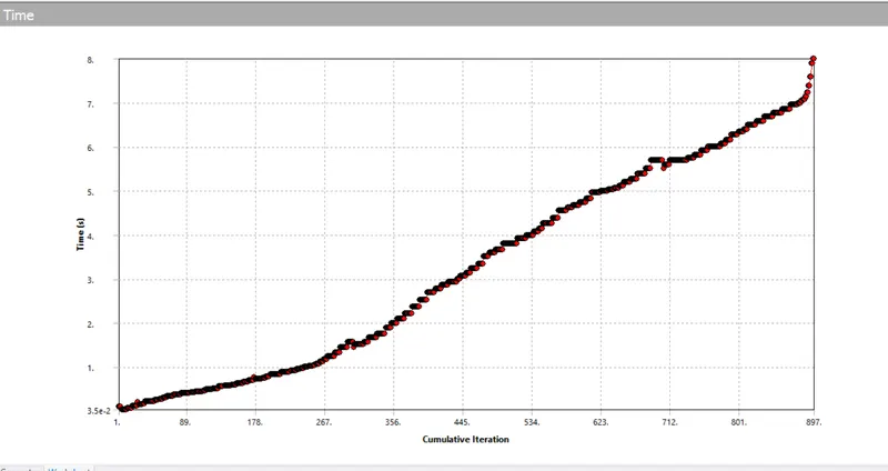
FIG.20 Time
FOLLOW THE SAME PROCEDURE FOR CASE-2 AND CASE-3, JUST CHANGE THE MATERIAL OF WIRE FOR THE RESPECTIVE CASES.
Case-2: Aluminium Alloy (Non Linear)
FIG 21: Material properties of a Aluminum Alloy
Case-3: Magnesium Alloy ( Non Linear)
FIG 22: Material properties of a Magnesium Alloy
SIMULATION RESULT:
Simulation results for case-1 the material used for the model is Copper alloy(NL), for case-2 Aluminium Alloy (NL) and for Case-3 Magnesium Alloy (NL). To find out the Equivalent stress, Equivalent elastic strain and Total Deformation and compare the results for the three materials.
Case-1.Copper Alloy NL
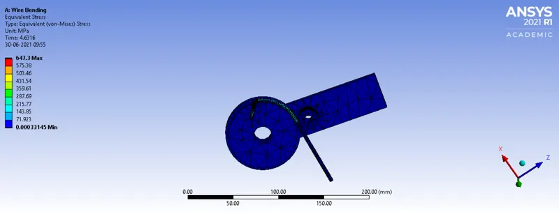
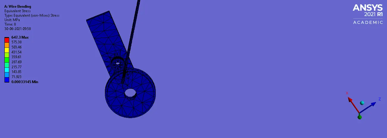
Fig 23: Equivalent Stress
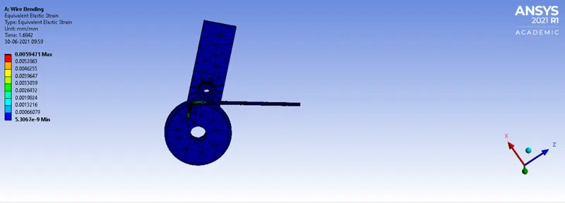
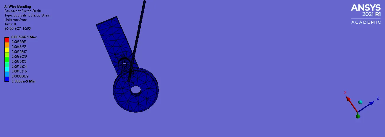
Fig 24: Equivalent Elastic Strain
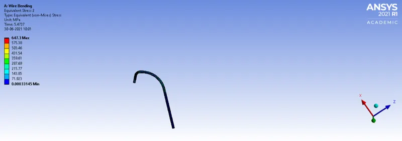
Fig 25: Equivalent Stress of Wire
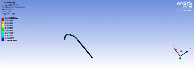
Fig 26: Equivalent Elastic Strain of Wire
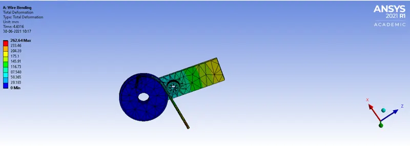
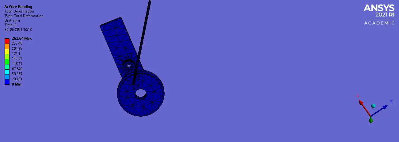
Fig 27: Total Deformation
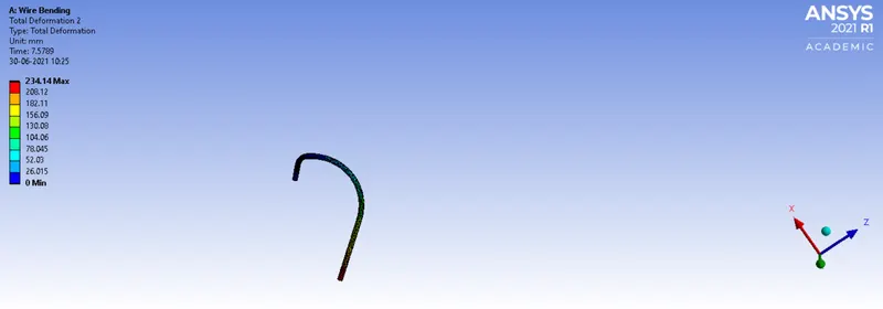
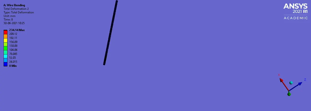
Fig 28: Total Deformation of Wire
Case-2: Aluminium Alloy (Non Linear)
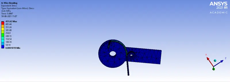
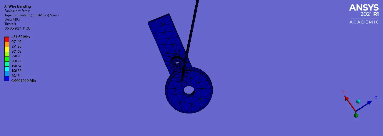
Fig 29: Equivalent Stress
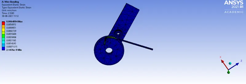
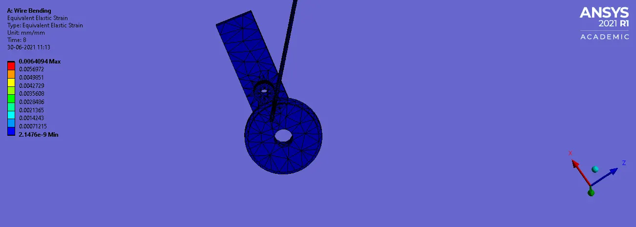
Fig 30: Equivalent Elastic Strain
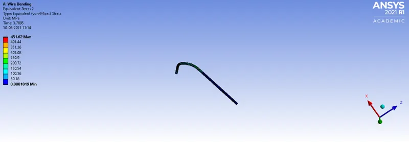
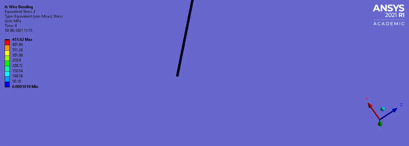
Fig 31: Equivalent Stress of Wire
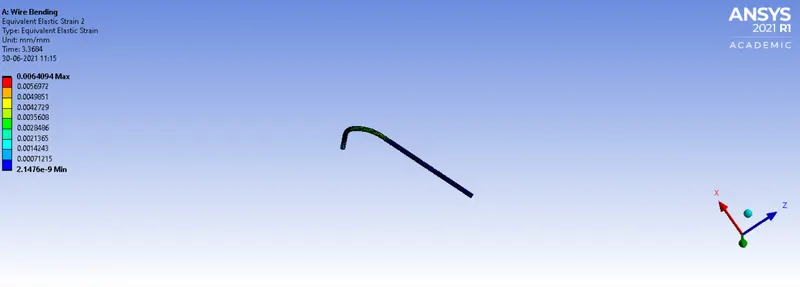
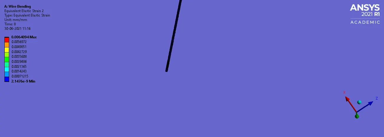
Fig 32: Equivalent Elastic Strain of Wire
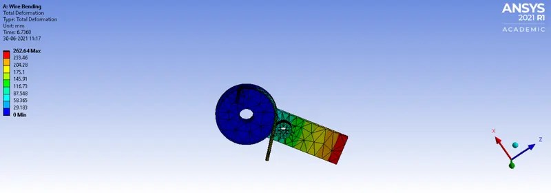
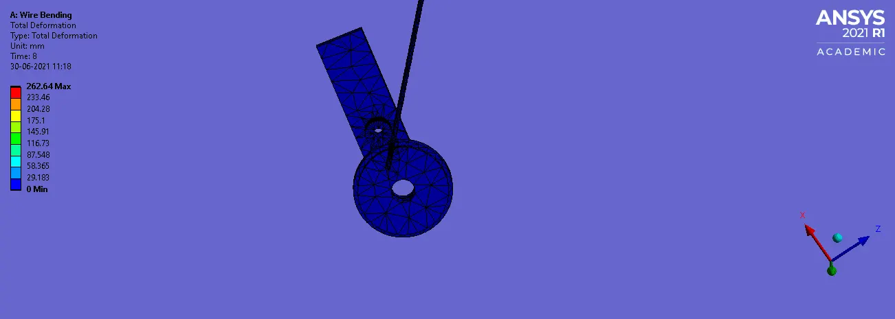
Fig 33: Total Deformation
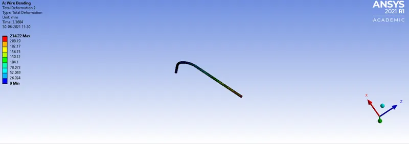
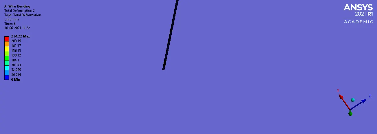
Fig 34: Total Deformation of Wire
Case-3: Magnesium Alloy ( Non Linear)
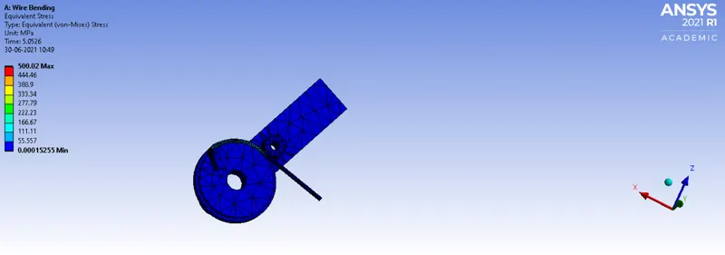
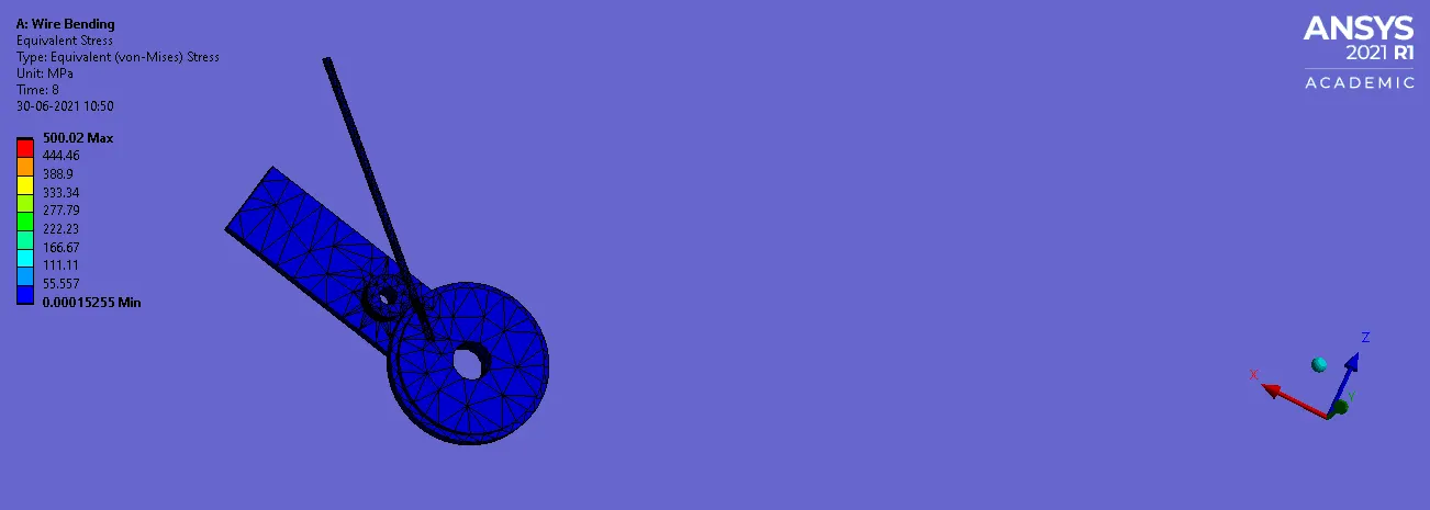
Fig 35: Equivalent Stress
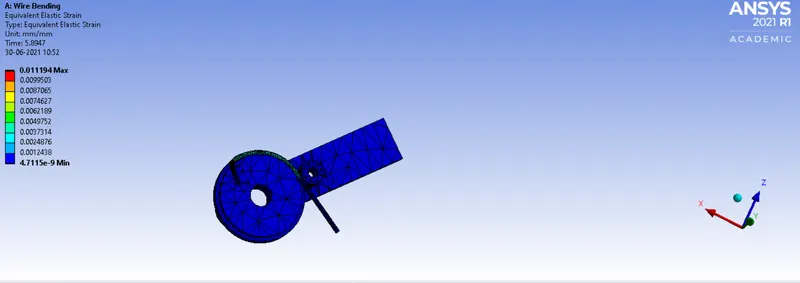
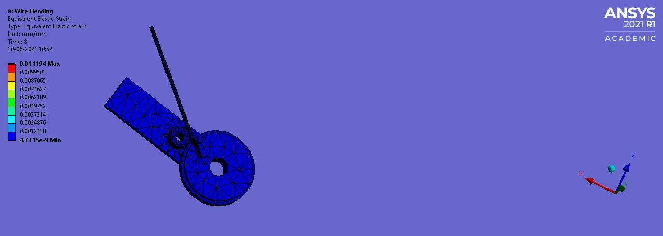
Fig 36: Equivalent Elastic Strain
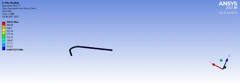
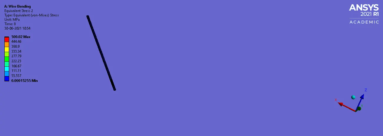
Fig 37: Equivalent Stress of Wire
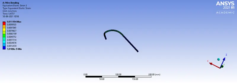
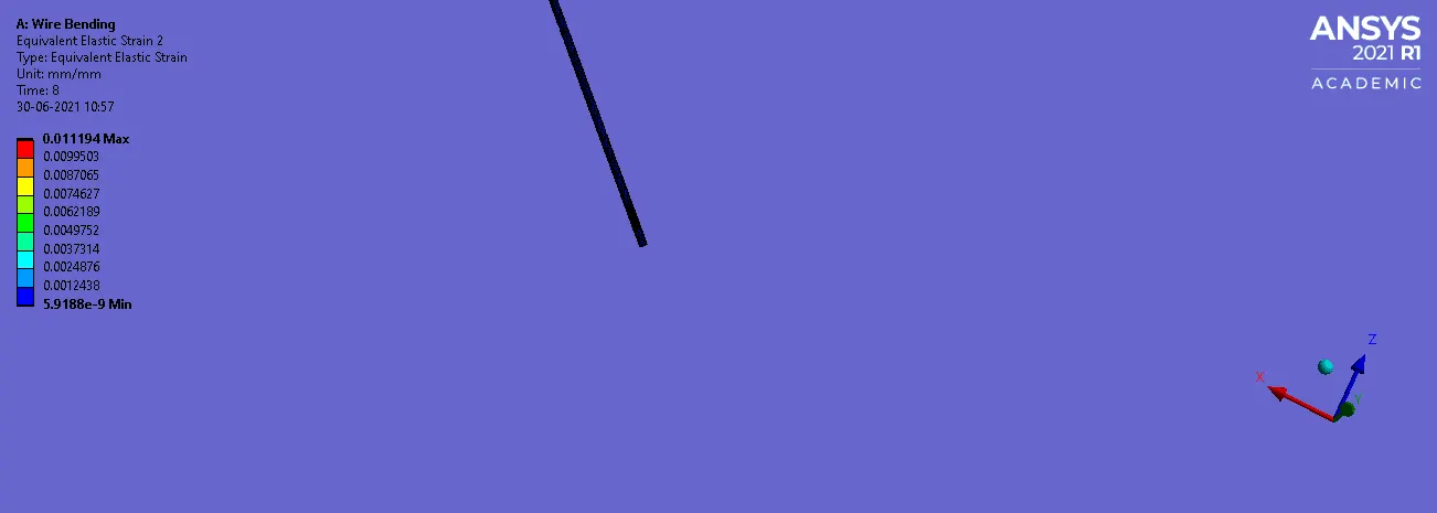
Fig 38: Equivalent Elastic Strain of Wire
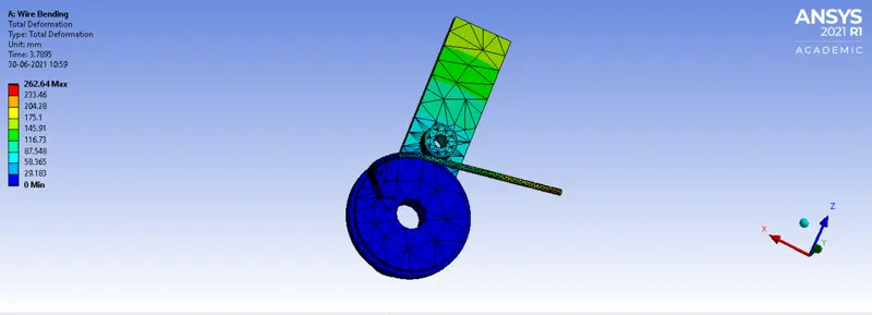
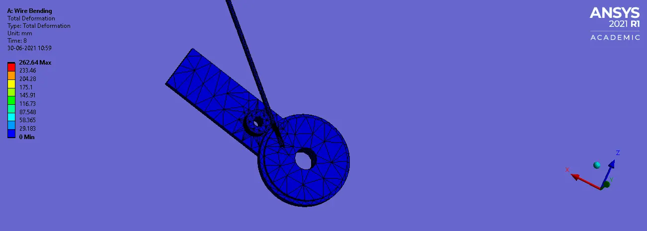
Fig 39: Total Deformation
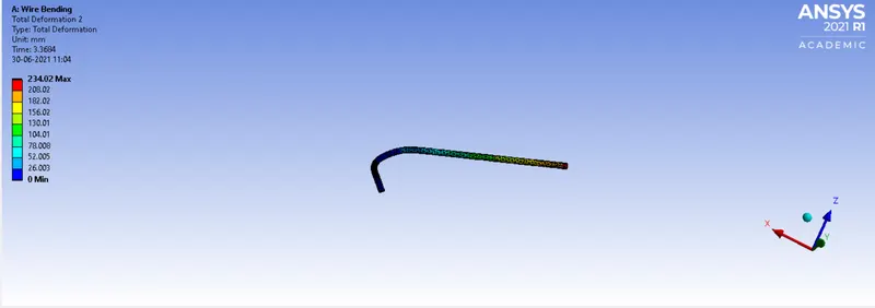
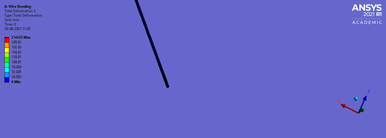
Fig 40: Total Deformation of Wire
TABULAR RESULTS
| MATERIAL | Equivalent Stress | Equivalent Elastic Strain | Equivalent Stress of Wire | Equivalent Elastic Strain of Wire | Total Deformation | Total Deformation of Wire |
| Copper Alloy (Non Linear) |
MAX: 647.3 MIN: 0.00033145 |
MAX: 0.00594271 MIN: 5.3067e-9 |
MAX: 647.3 MIN: 0.00033145 |
MAX: 0.00594271 MIN: 5.3067e-9 |
MAX: 262.64 MIN: 0 |
MAX: 234.14 MIN: 0 |
| Aluminium Alloy (Non Linear) |
MAX: 451.62 MIN: 0.0001019 |
MAX: 0.0064094 MIN: 2.1476e-9 |
MAX: 451.62 MIN: 0.0001019 |
MAX: 0.0064094 MIN: 2.1476e-9 |
MAX: 262.64 MIN: 0 |
MAX: 234.22 MIN: 0 |
| Magnesium Alloy ( Non Linear) |
MAX: 500.02 MIN: 0.00015255 |
MAX: 0.011194 MIN: 4.7115e-9 |
MAX: 500.02 MIN: 0.00015255 |
MAX: 0.011194 MIN: 5.9188e-9 |
MAX: 262.64 MIN: 0 |
MAX: 234.02 MIN: 0 |
CONCLUSION:
From the above result copper material experiences more stress of 647.3, when compared with other two material. Aluminum material experiences less stress of 451.62, when compared with other two material. Magnesium material experiences moderate stress when compared with other two material. Magnesium material experiences high strain when compared with other two material. The total deformation for all material remains same.
Link: https://drive.google.com/drive/folders/1xBOPFHjGGCNTgjOxNHVkpfQ3Zi82m80J?usp=sharing