Week 8 Worm Gear Challenge
Worm Gear Challenge
OBJECTIVE: The main objective of this challenge is to perform a Transient structural Analysis on a worm gear assembly with finer mesh. To cut the gear by half so as to bring the model within limits, to rotate the worm so as to get to almost end of the half cut and to get results for Equivalent stress, Equivalent elastic strain and the total deformation in the model.
SOFTWARE USED: ANSYS Workbench 2021 R1 and ANSYS Mechanical for Analysis.
INTRODUCTION:
A worm drive is a gear arrangement in which a worm (which is a gear in the form of a screw) meshes with a worm wheel (which is similar in appearance to a spur gear). The two elements are also called the worm screw and worm gear. The terminology is often confused by imprecise use of the term worm gear to refer to the worm, the worm wheel, or the worm drive as a unit.
Like other gear arrangements, a worm drive can reduce rotational speed or transmit higher torque. A worm is an example of a screw, one of the six simple machines. One of the major advantages of worm drive units are that they can transfer motion in 90 degrees. The worm in the worm drive may have single or multiple starts. Each full 360-degree turn of a single-start worm advances the wheel by one tooth. For a multi-start worm, the gear reduction equals the number of teeth on the wheel divided by the number of starts on the worm. Both the sliding and the rolling actions of the worm and the wheel come into play during the meshing of the gears. The sliding contact dominates at high reduction ratios. Much heat is produced due to friction while sliding, which limits the efficiency of worm drives to 30 to 90 percent. The worm and the wheel are made of dissimilar metals, in order to minimize the friction and loss in efficiency.
Fig.1: Worm Gear
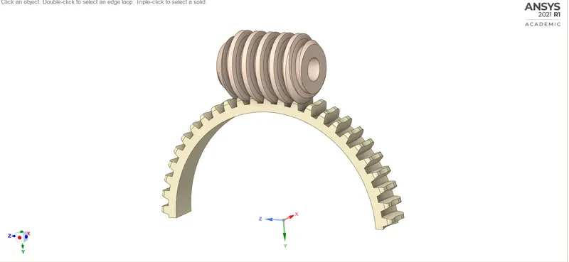
FIG.2: CAD MODEL
PROCEDURE:
1. Open the ANSYS Workbench software. Under the Analysis system select the Transient structural and wait for few seconds to pop up the window, which contains Engineering data, Geometry, Model, setup, Solution and Results.
2. Rename the Transient structural as Worm Gear.
3. Under geometry import the Worm Gear model.
4. Update the model by right click and edit the Model for Preprocessing.
5. Wait for few seconds and ANSYS Mechanical will open as shown below. Rename the model as Worm and Gear.
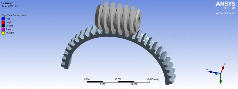
FIG.3: CAD model of Long Piston model.
6. Assign the material to the model. Default we have structural steel.
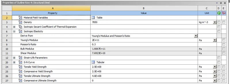
FIG 4: Material properties of a Structural Steel
7. Connections plays a major role in analysis, so click on connections and we can see the default contacts between the parts. Select some more faces for contacts as shown below. Make half portion of gear to contact bodies, change the type to frictionless and remaining as default.
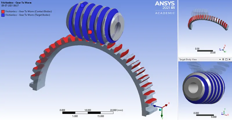
Fig 5: Frictionless contact between the Worm and Gear
8. In ANSYS automatic mesh will be performed with Default mesh size and select the sizing option and select the faces as shown below and assign the element size as 1mm. Assign global mesh size as 4mm.
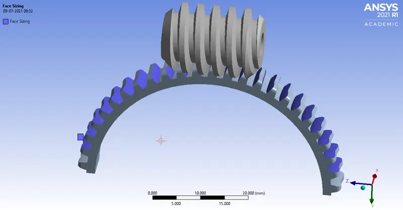
Fig.6: Sizing
Again select the sizing option and select the faces as shown below and assign the element size as 1mm.
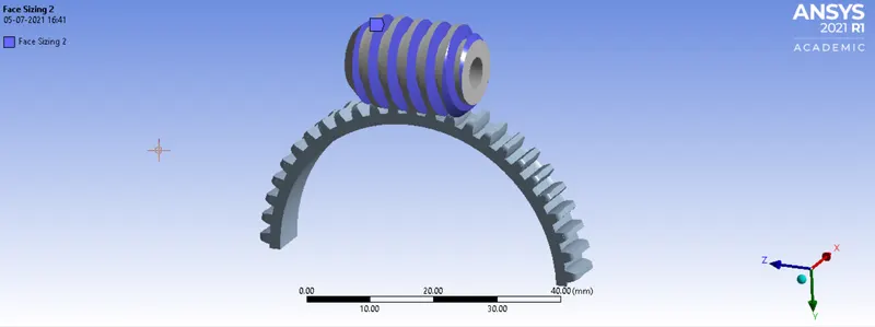
Fig.7: Sizing
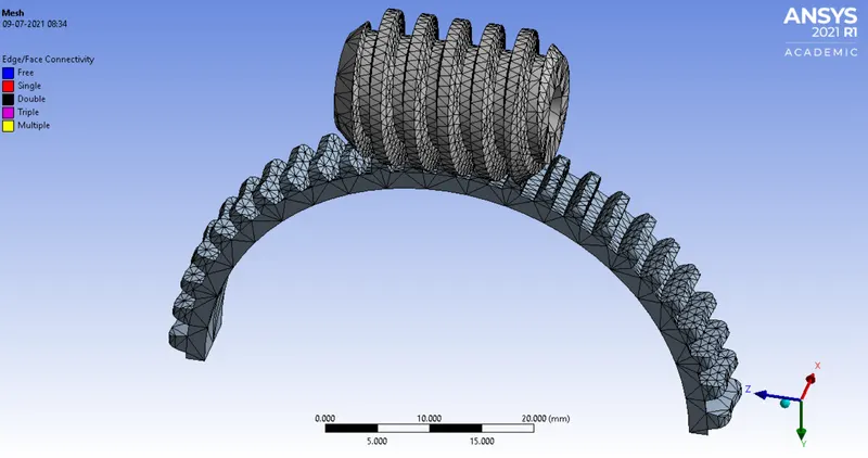
Fig.8: Meshing
9. Insert a revolute joint to the Gear. Change the connection type as body to ground and select the face as shown below.
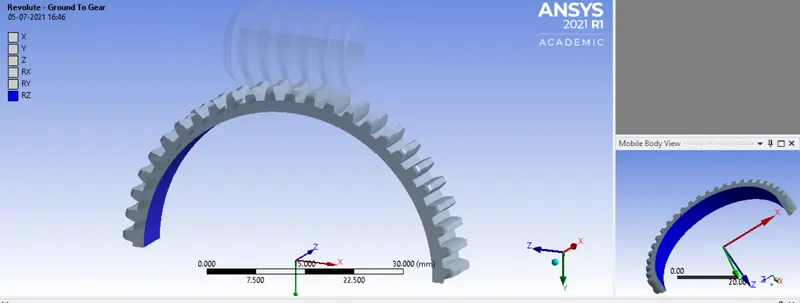
Fig.9:Revolute joint for the model
Again Insert a revolute joint to the Worm. Change the connection type as body to ground and select the face as shown below.
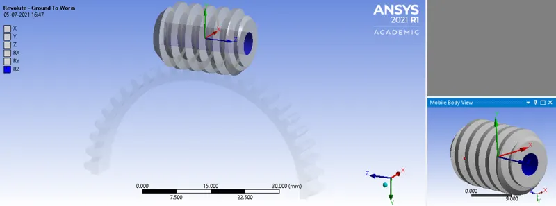
Fig.10:Revolute joint for the model
10. Analysis settings Change no. of steps as 55, for 1st step add initial time step as 0.2, min type step as 0.2, Max time step as 0.5, Weak spring as program controlled, large deflection on, output controls all as yes, expect for contact miscellneous, For 2nd to 55th step follow the same time step value and carry over time step as on.
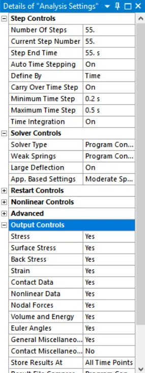
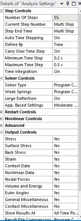
FIG 11: Analysis settings
11. Joint Load for the worm is defined by inserting a joint load and change the type as rotation, select the face for scope and magnitude of 0,50,100,150,200,250,300,350,400,450,500,550,600,650,700,750,800,850,900,950,1000,1050,1100,1150,1200,1250,1300,1350,1400,
1450,1500,1550,1600,1650,1700,1750,1800,1850,1900,1950,2000,2050,2100,2150,2200,2250,2300,2350,2400,2450,2500,2550,2600,
2650,2700,2750
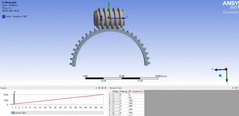
Fig.12: Joint load
12. Now request for the outputs such as equivalent stress, equivalent elastic strain and the total deformation in the model.
13. SOLVE the solution and we can see the simulation run under soluion information.
FIG13: Solver output
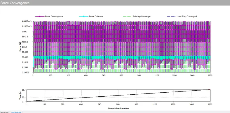
Fig.14: Force convergence
SIMULATION RESULT:
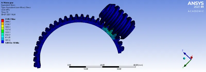
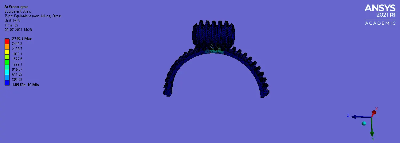
Fig 15: Equivalent Stress
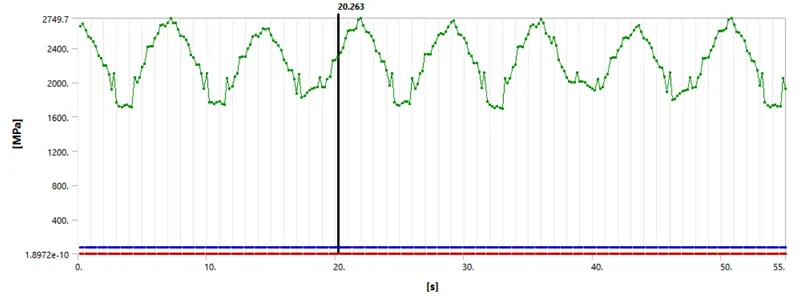
Fig 16: Equivalent Stress graph
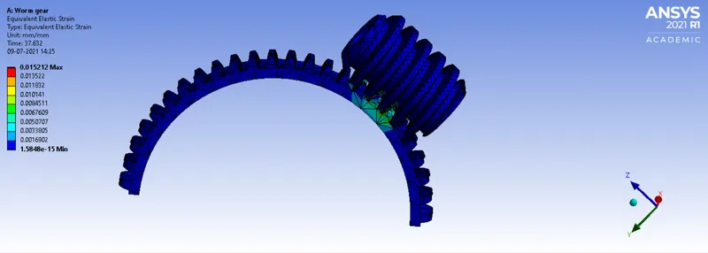
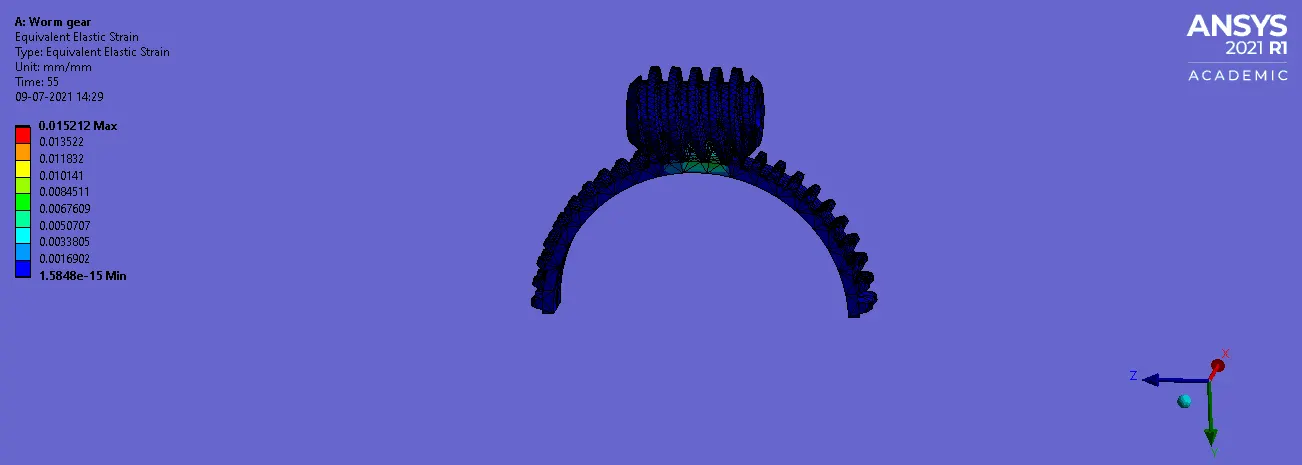
Fig 17: Equivalent Elastic Strain
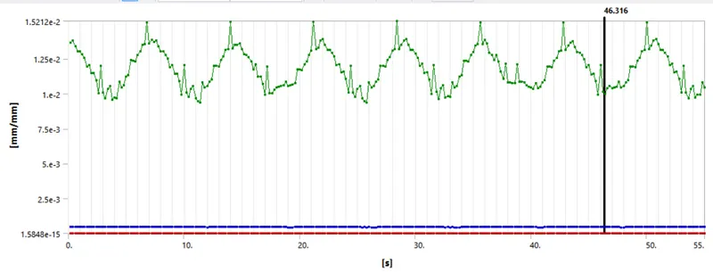
Fig 18: Equivalent Elastic Strain graph
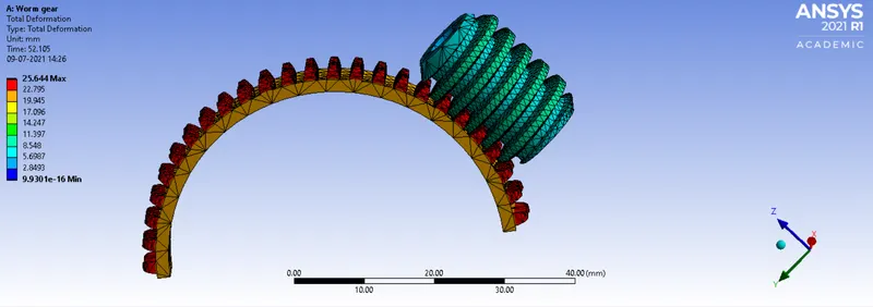
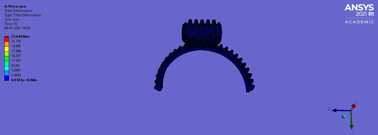
Fig 19: Total Deformation
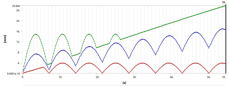
Fig 20: Total Deformation graph
Tabular of results:
| Sl No. | Material | Equivalent Stress (MPa) | Equivalent Elastic Strain | Total Deformation (mm) |
| 1. | Structural Steel |
Max: 1927.6 MPa Min: 1.2134e-007 MPa |
Max: 1.044e-002 mm/mm Min: 6.2996e-013 mm/mm |
Max: 25.644 mm Min: 3.501 mm |
CONCLUSION:
From the above result we can conclude that the Maximum equivalent stress is 1927.6 MPa and Maximum Equivalent Elastic Strain is 1.044e-002 mm/mm and the Maximum Total Deformation is 25.644 mm. As per the given question the gear is cutted half and finer mesh is used. Finally the worm reaches almost the cut portion of gear.
Link: https://drive.google.com/drive/folders/1lOhpulKMGvsYodl_FrRwr1iPo_dzJjLC?usp=sharing