Week 7-Long Piston With Cam
Long Piston With Cam
OBJECTIVE: The main objective of this challenge is to perform a Transient structural Analysis on a piston and cam mechanism and to run the analysis with Frictionless contact, Frictional with 0.1 and 0.2 as the frictional contact for a total of 3 cases, as well as to find out the Equivalent Stress, Directional Deformation and Equivalent Elastic Strain and compare them for all the three cases.
SOFTWARE USED: ANSYS Workbench 2021 R1 and ANSYS Mechanical for Analysis.
INTRODUCTION:
A piston is a component of reciprocating engines, reciprocating pumps, gas compressors, hydraulic cylinders and pneumatic cylinders, among other similar mechanisms. It is the moving component that is contained by a cylinder and is made gas-tight by piston rings.
A cam is a rotating or sliding piece in a mechanical linkage used especially in transforming rotary motion into linear motion. It is often a part of a rotating wheel (e.g. an eccentric wheel) or shaft (e.g. a cylinder with an irregular shape) that strikes a lever at one or more points on its circular pat
Fig.1: Animation of Piston and Cam
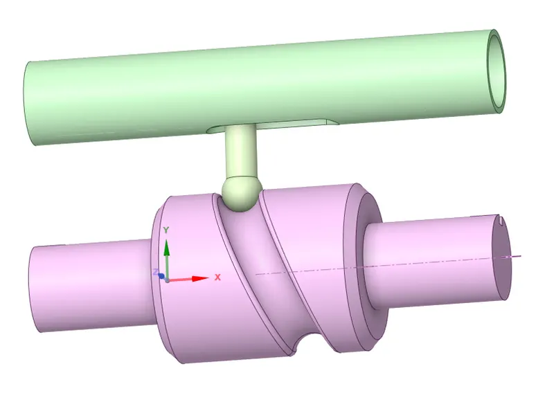
FIG.2: CAD MODEL
PROCEDURE:
1. Open the ANSYS Workbench software. Under the Analysis system select the Transient structural and wait for few seconds to pop up the window, which contains Engineering data, Geometry, Model, setup, Solution and Results.
2. Rename the Transient structural as Long Piston.
3. Under geometry import the Long Piston model.
4. Update the model by right click and edit the Model for Preprocessing.
5. Wait for few seconds and ANSYS Mechanical will open as shown below. Rename the model as Barrel, Barrel Cam and Cam Follower.
Change Barrel and Barrel Cam as rigid, then the solver consider them as mass, which will be concentrated on their body centers and consider them as point masses.
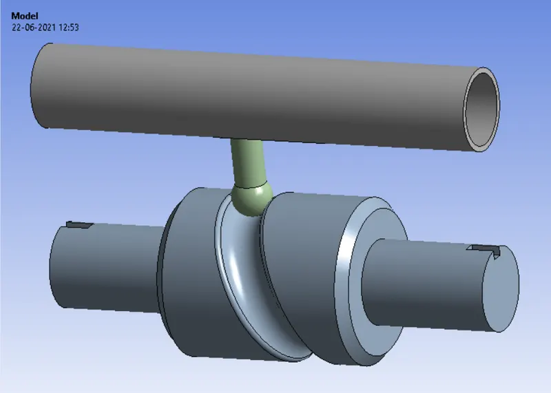
FIG.3: CAD model of Long Piston model.
6. Assign the material to the model. Default we have structural steel.
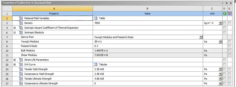
FIG 4: Material properties of a Structural Steel
7. Connections plays a major role in analysis, so click on connections and we can see the default contacts between the parts with a question mark. It can be removed by selecting two contacts and flip them. Select the contacts as shown below.
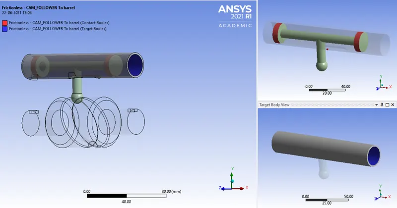
Fig 5: Frictional contact between the Barrel and Piston
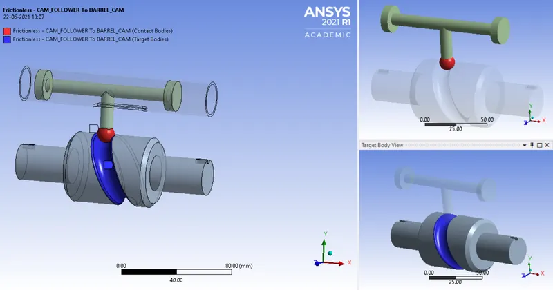
Fig 6: Frictional contact between the Follower and Cam
Select both the contacts and change the type to frictionless for case-1, and Frictional with 0.1 and 0.2 as the frictional contact for case-2 and case-3. Remaining steps are same for all the three cases.
8. Inserting the Joints for the model
Insert a fixed joint for the barrel. Change the connection type as body to ground.
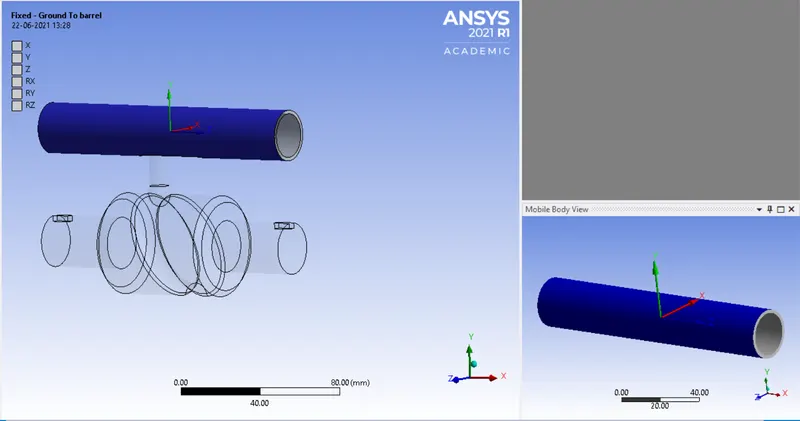
Fig.7: Fixed joint for the model
Insert a revolute joint to the cam. Change the connection type as body to ground
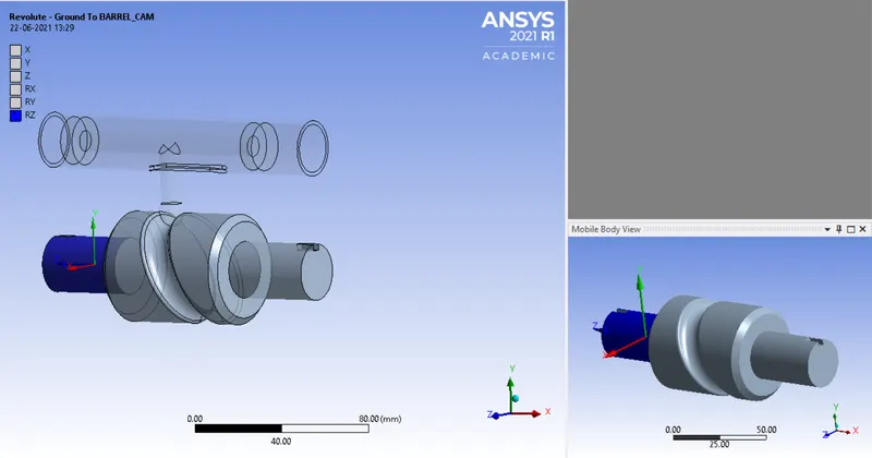
Fig.8:Revolute joint for the model
Insert a translational joint to the barrel and cam follower. Change the connection type as body to body. Select the face for mobile and reference as shown below.
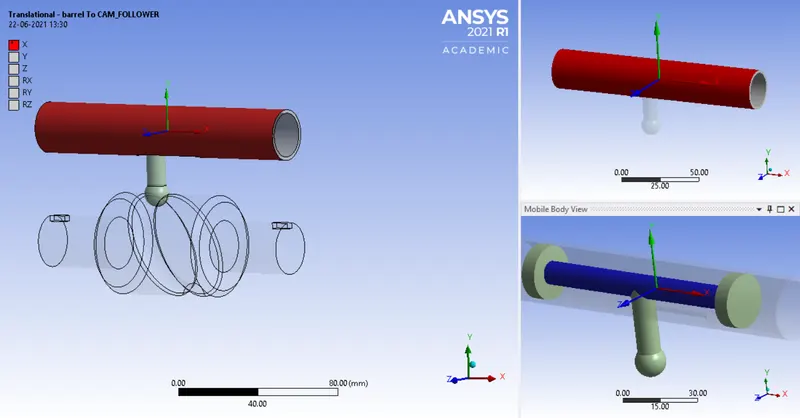
Fig.9: Translational joint for the model
9. In ANSYS automatic mesh will be performed with Default mesh size and select the sizing option and select the faces as shown below and assign the element size as 1mm.
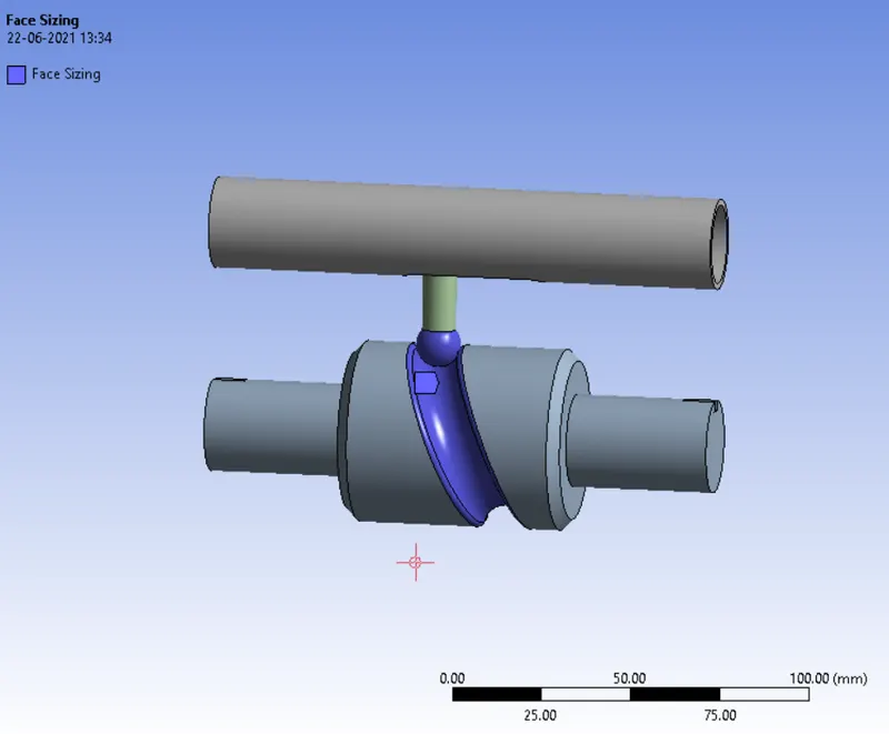
Fig.10: Selecting face for meshing
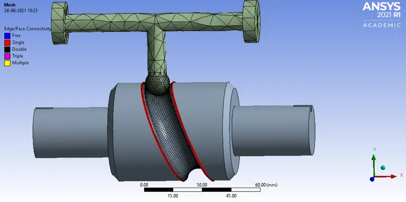
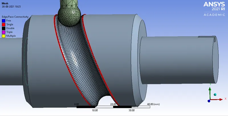
Fig.11: Meshing
10. Analysis settings Change no. of steps as 9, for 1st step add initial time step as 0.1, min type step as 5e^-2, Max time step as 0.2, Weak spring as program controlled, large deflection on, Non linear control-Stabilization as Constant,energy dissipation 0.1, output controls all as yes, expect for contact miscellneous, Activation for first step as Yes. For 2nd to 9th step change initial time step as 0.1, min type step as 5e^-2, Max time step as 0.3, Non linear control-Stabilization as Constant,energy dissipation 0.1, Activation for first step as Yes.
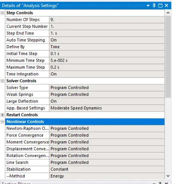
FIG 12: Analysis settings
11. Joint Load for the barrel is defined by inserting a joint load and change the type as rotation, select the face for scope and magnitude of 0,30,60,90,120,150,180,210,240,270.
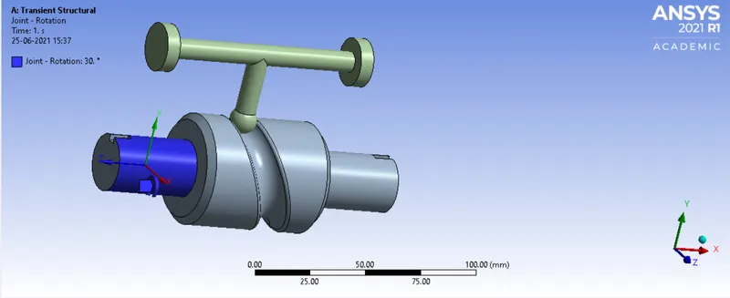
Fig.13: Joint load
12. Now request for the outputs such as equivalent stress, equivalent elastic strain, directional deformation in Y-Direction.
13. SOLVE the solution and we can see the simulation run under soluion information.
FIG14: Solver output
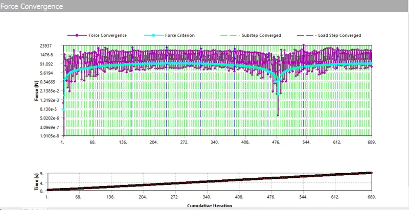
FIG.15: Force convergence
SIMULATION RESULT: frictionless
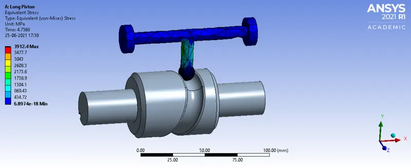
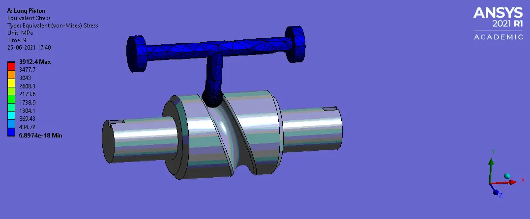
Fig 16: Equivalent Stress
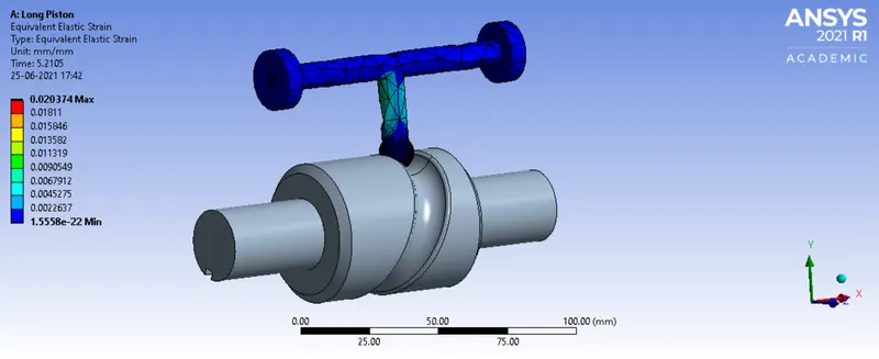
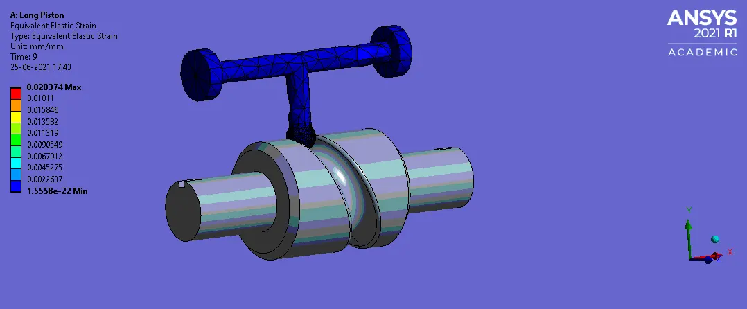
Fig 17: Equivalent Elastic Strain
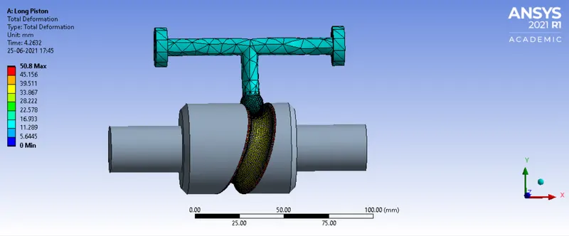
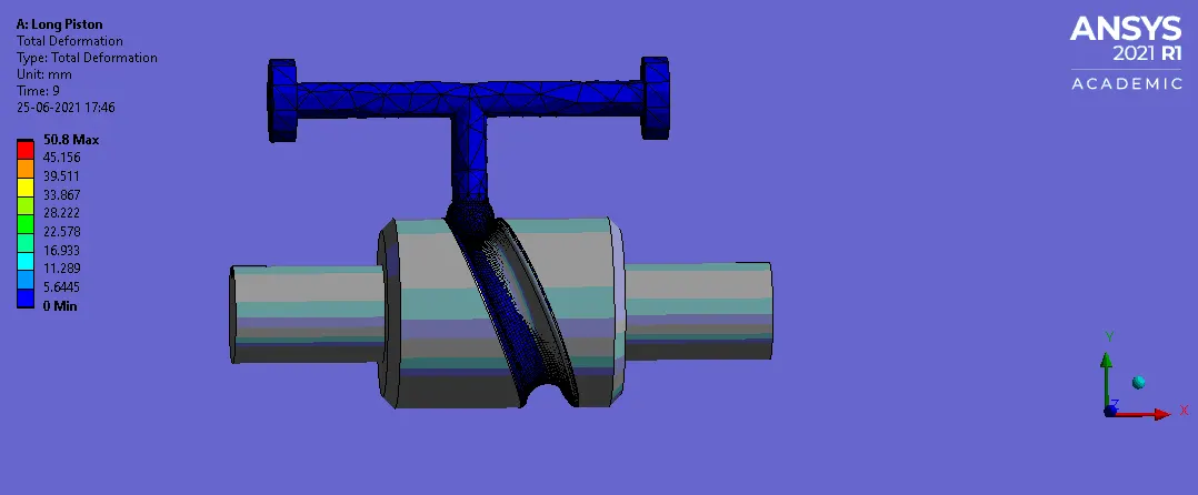
Fig 18: Total Deformation
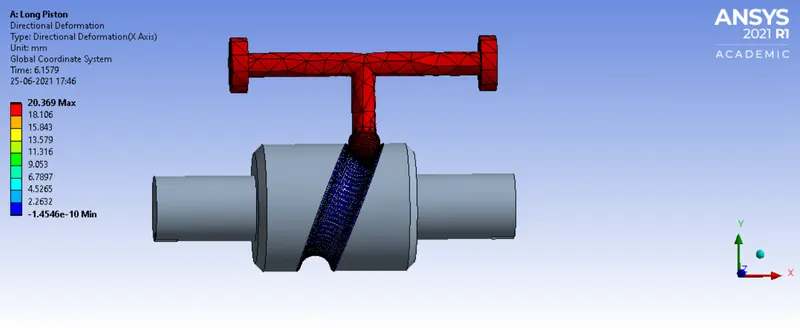
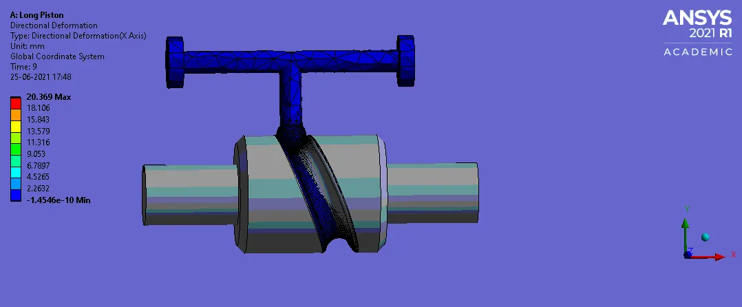
FIG: 19 DIRECTIONAL DEFORMATION (X-Axis)
SIMULATION RESULT: with frictional coefficient of 0.1
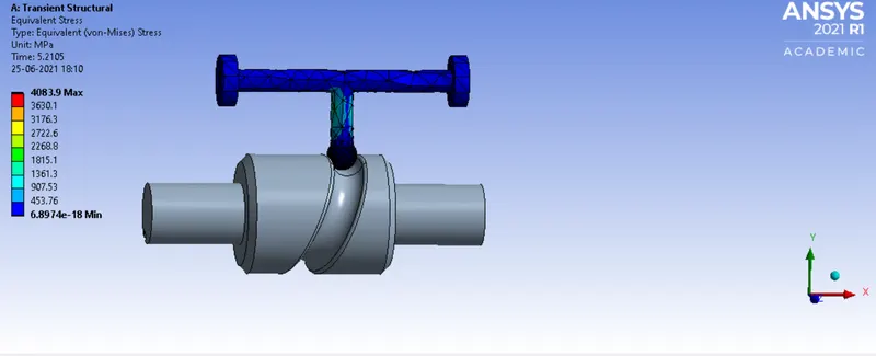
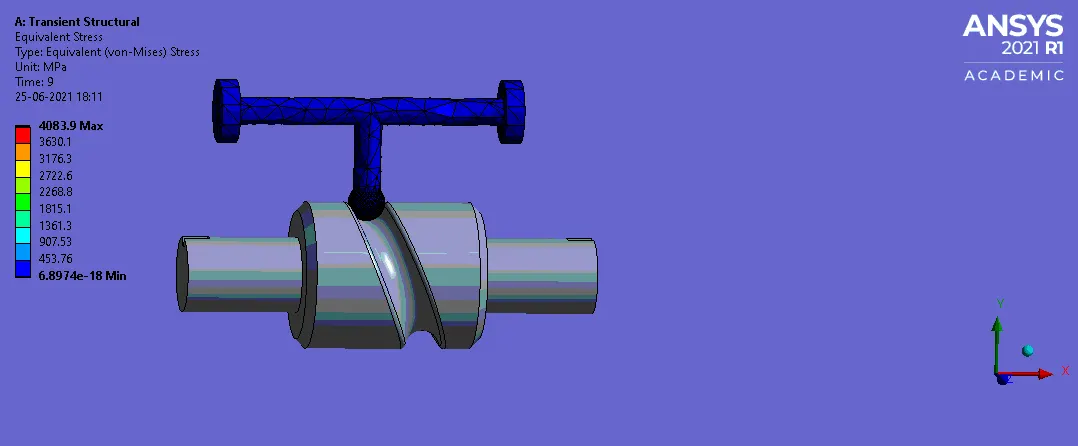
Fig 20: Equivalent Stress
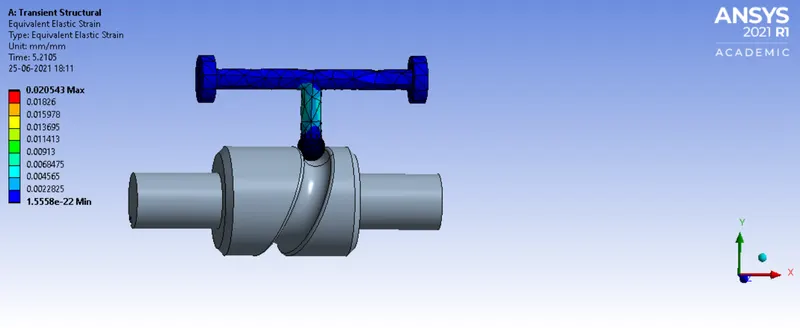
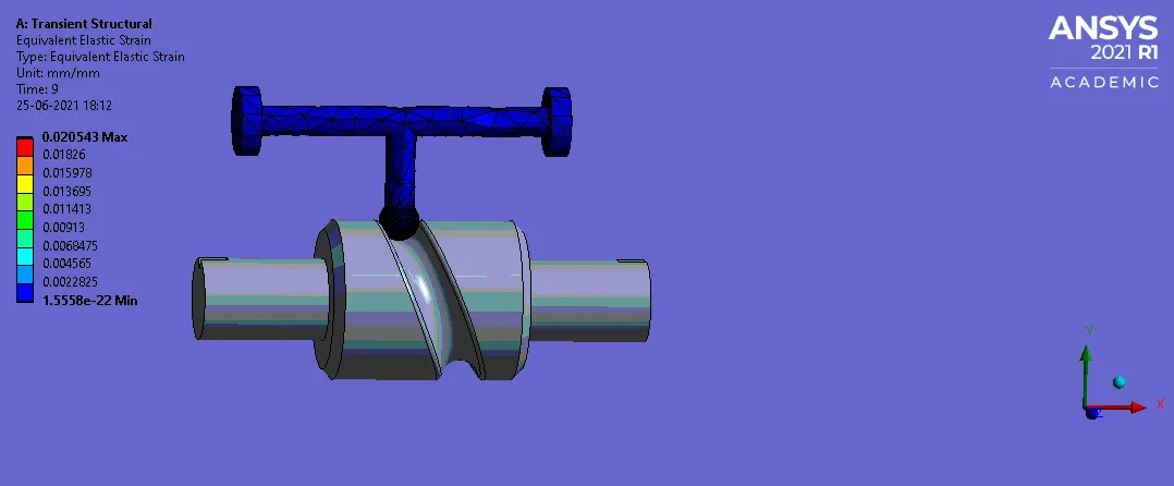
Fig 21: Equivalent Elastic Strain
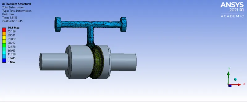
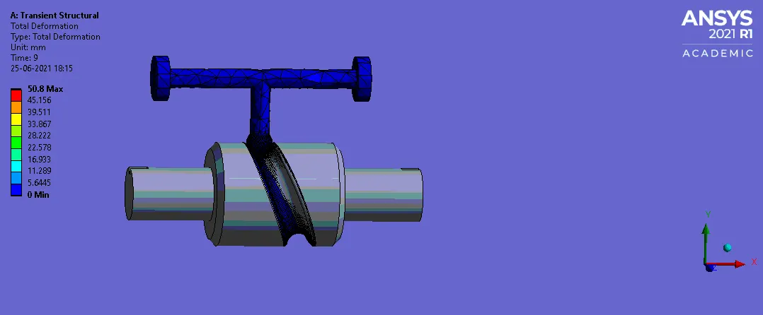
Fig 22: Total Deformation
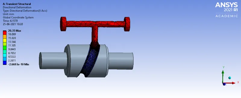
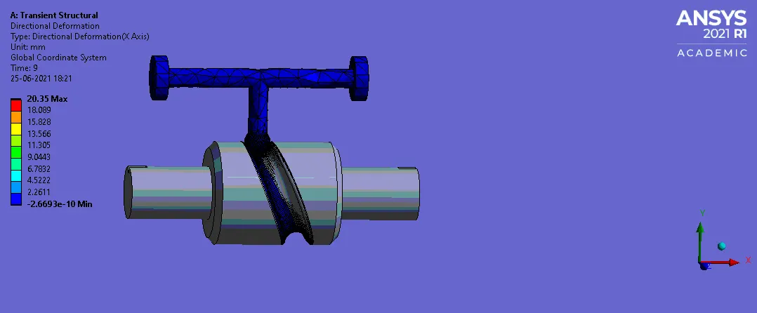
FIG: 23 DIRECTIONAL DEFORMATION (X-Axis)
SIMULATION RESULT: with frictional coefficient of 0.2
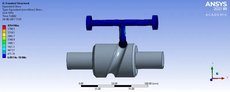
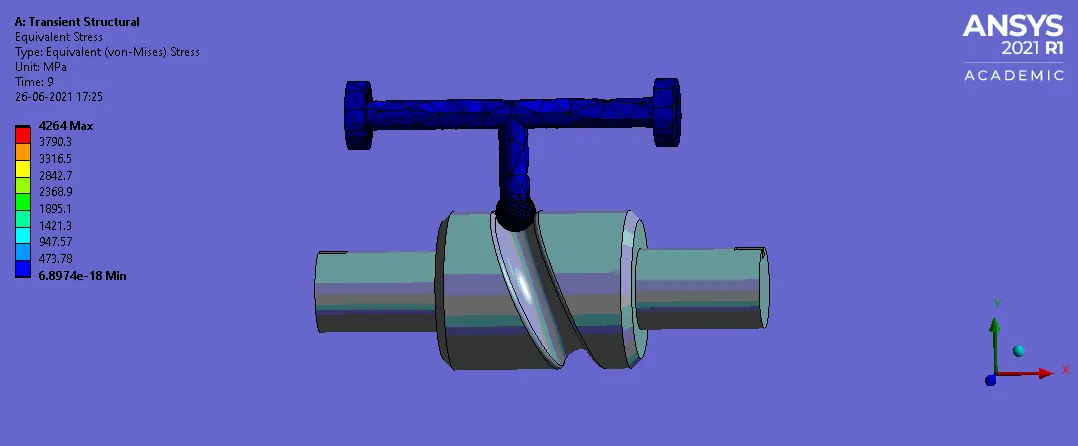
Fig 24: Equivalent Stress
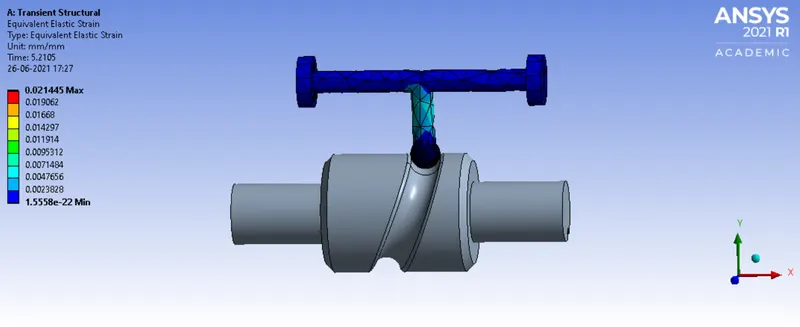
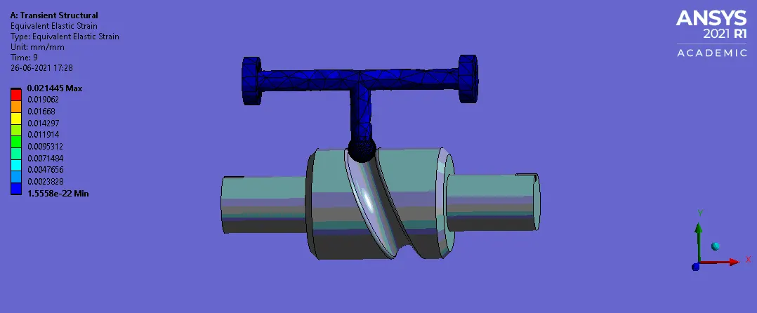
Fig 25: Equivalent Elastic Strain
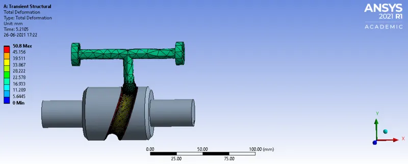
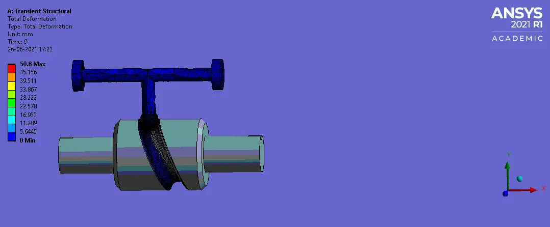
Fig 26: Total Deformation
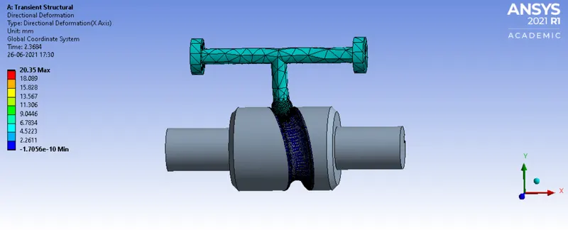
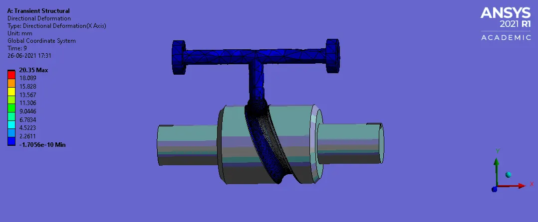
FIG: 27 DIRECTIONAL DEFORMATION (X-Axis)
Camparism of results:
| MODE | Equivalent Stress (MPa) | Equivalent Elastic Strain | Total Deformation (mm) | Directional Deformation(X-axis) (mm) |
| With frictionless CONTACT |
MAX: 3912.4 MIN: 6.8974e^-18 |
MAX: 0.020374 MIN: 1.5558e^-22 |
MAX: 50.8 MIN: 0 |
MAX: 20.369 MIN: -1.4546e^-10 |
| Frictional Contact With Coefficient of friction as 0.1 |
MAX: 4083.9 MIN: 6.8974e^-18 |
MAX: 0.020543 MIN: 1.5558e^-22 |
MAX: 50.8 MIN: 0 |
MAX: 20.35 MIN: -2.6693e^-10 |
| Frictional Contact With Coefficient of friction as 0.2 |
MAX: 4264 MIN: 6.8974e^-18 |
MAX: 0.021445 MIN: 1.5558e^-22 |
MAX: 50.8 MIN: 0 |
MAX: 20.35 MIN: -1.7056e^-10 |
CONCLUSION:
From the above result we can conclude that the the minium equivalent stress of 3912.4MPa is experienced at frictionless contact, and maximum equivalent stress of 4264MPa is experienced at frictional contact with coefficient of friction as 0.2. So the equivalent stress of Frictional Contact With Coefficient of friction as 0.2 is greater than the Frictional Contact With Coefficient of friction as 0.1 is also greater than the With frictionless CONTACT. The variation between the result is due to type of contact we used as well as the coefficient of friction. Higher in coefficient of friction value will experience high equivalent stress and Lower in coefficient of friction value will experience Low equivalent stress. The overall Equivalent Elastic Strain, Total Deformation and Directional Deformation are same with some small values.
LINK: https://drive.google.com/drive/folders/1SX7-EfiN6PnQhhFvhIqiA84NZ3-6PCS4?usp=sharing