Week 4- Rolling operation
Rolling operation
OBJECTIVE: The objective of this challenge is to perform a static structural analysis and to Simulate the rolling operation on a workpiece made of copper for 14 steps and to ensure that the edge of the workpiece is displaced by 90mm. Finally to find out the Equivalent stress for the whole setup, Equivalent Plastic strain for the workpiece, Directional Deformation in the Z axis for the workpiece and to Prove that the workpiece had displaced by 90mm.
SOFTWARE USED: ANSYS Workbench 2021 R1 and ANSYS Mechanical for Analysis.
INTRODUCTION:
Rolling:
In metalworking, rolling is a metal forming process in which metal stock is passed through one or more pairs of rolls to reduce the thickness, to make the thickness uniform, and/or to impart a desired mechanical property. The concept is similar to the rolling of dough. Rolling is classified according to the temperature of the metal rolled. If the temperature of the metal is above its recrystallization temperature, then the process is known as hot rolling. If the temperature of the metal is below its recrystallization temperature, the process is known as cold rolling. In terms of usage, hot rolling processes more tonnage than any other manufacturing process, and cold rolling processes the most tonnage out of all cold working processes. Roll stands holding pairs of rolls are grouped together into rolling mills that can quickly process metal, typically steel, into products such as structural steel (I-Beams, angle stock, channel stock), bar-stock and rails. Most steel mills have rolling mill divisions that convert the semi-finished casting products into finished products.
There are many types of rolling processes, including ring rolling, roll bending, roll forming, profile rolling, and controlled rolling.
Fig.1: Rolling
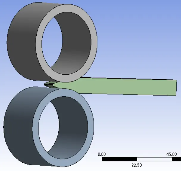
Fig 2: CAD Model
The CAD Model consists of two rollers and a workpiece. Two rollers will rotate in opposite direction and metal is feed in between the rollers and thus the thickness of the metal is reduced.
PROCEDURE:
1. Open the ANSYS Workbench software. Under the Analysis system select the Static structural and wait for few seconds to pop up the window, which contains Engineering data, Geometry, Model, setup, Solution and Results.
2. Rename the static structural as Rolling Copper.
3. Under geometry import the Rolling Copper model. Edit the model by importing it into spaceclaim, increase the length of the workpiece by 60mm and decrease its size on both sides by 8mm.
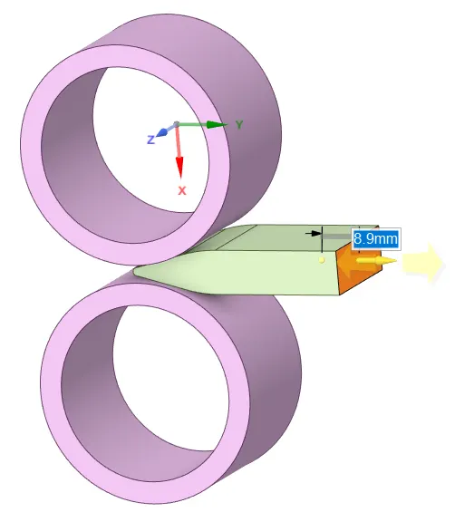
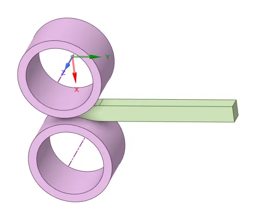
Fig.3: Increase the length by 60mm
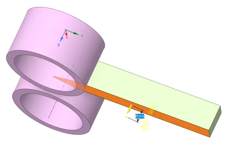
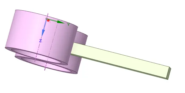
Fig.4: Decrease its size on both sides by 8mm
4. Update the model by right click and edit the Model for Preprocessing.
5. Wait for few seconds and ANSYS Mechanical will open as shown below.
Fig 5: CAD Model
6. Under Geometry rename its parts as Wheel-1, Wheel-2, Workpiece and Assign the material to the model. Assign Structural Steel for Both the Wheels and assign Copper Alloy NL to the workpiece.
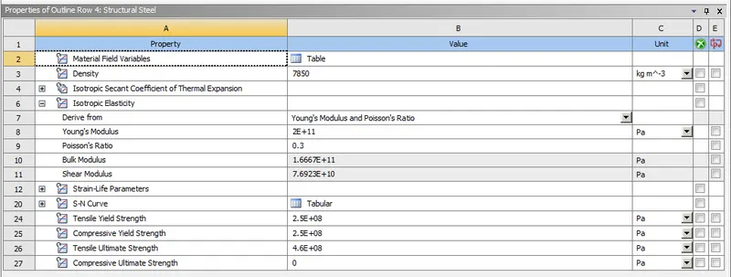
FIG 6: Material properties of a Structural Steel
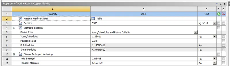
FIG 7: Material properties of a Copper Alloy NL
7. Frictional contact between the Workpiece to Wheel 1 and the Workpiece to Wheel 2 are Defined with a frictional coefficient of 0.2, Formulation as Augmented lagrange, Normal Stiffness as 0.1 factor, update stiffness as each itration and interface treatment as Add offset Ramped effects.
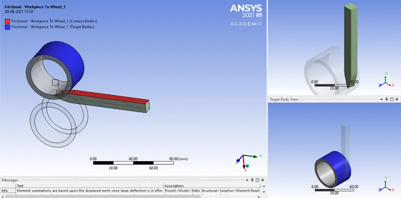
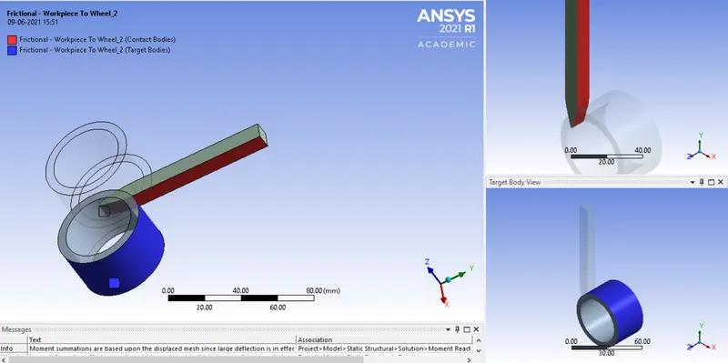
Fig 8: Frictional contact between the Workpiece to Wheels
8. Insert a Joints for the two wheels by right clicking on connections and insert joint. Change Connection type as body to ground, type as cylindrical and select the respective inner surface of wheels for scope.
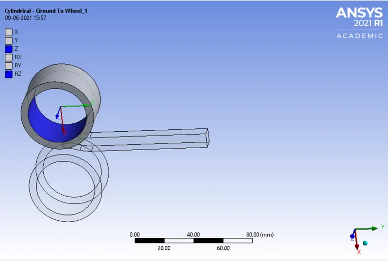
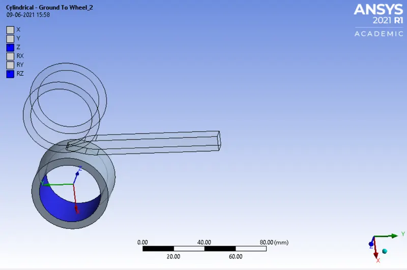
Fig 9: Joints for the two wheels
Then apply the joint load by right clicking on static structural - insert - joint load. Select the respected joint, change DOF as ROTATION-Z, type as Rotational apply the magnitude in tabular data such as 0, 7, 15, 30, 45, 60, 75, 90, 105, 120, 135, 150, 165, 180 and 195. Follow the same for another joint and use negative sign for the data to change the direction of rotation.
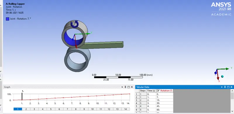
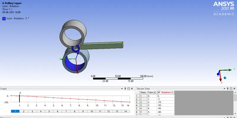
Fig 10: Applying the joint load
Inserting displacement for the work piece by inserting displacement and assigning the value as -3, -6.5, -13, -19.5, -26, -32.5, -39, -45.5, -52, -58.5, -65, -71.5, -79 and -90
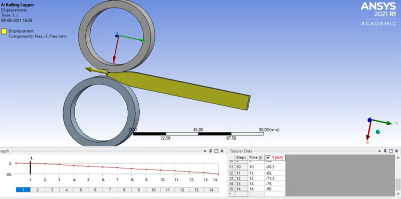
Fig 11: Applying the Displacement
9. In ANSYS automatic mesh will be performed with Default mesh size and change the mesh size as 6mm.(i.e Ansys student version will have a limted number of elements and nodes.) Apply the mesh size of 3mm to the workpiece. Use method option to assign tetrahedrans for the model.
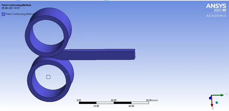
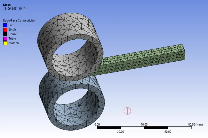
Fig 12: Selecting method for assigning the tetrahedrans mesh.
Be aware of ANSYS Student Edition and don't go beyond the size limit. The below figure shows the mesh size along with its number of nodes and elements.
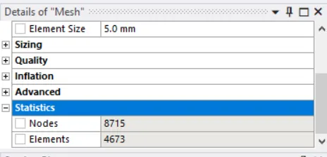
Fig 13: statistics of meshin
10. Analysis settings Change no. of steps as 14, large deflection on, non linear stabilization as constant, energy disipation as 0.1.
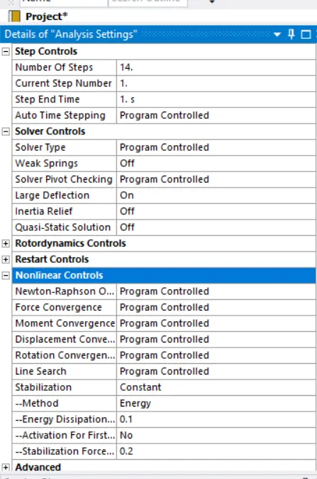
FIG 14: Analysis settings
11. Now request for the outputs such as equivalent stress, equivalent elastic strain, directional deformation, strees and contact Tool.
12. SOLVE the solution and we can see the simulation run under soluion information.
RESULT:
Simulation results for the rolling operation on a workpiece made of copper.
Fig 18: Equivalent Stress
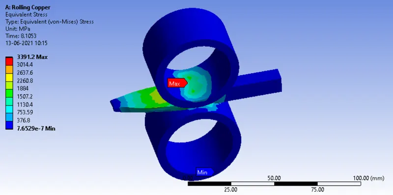
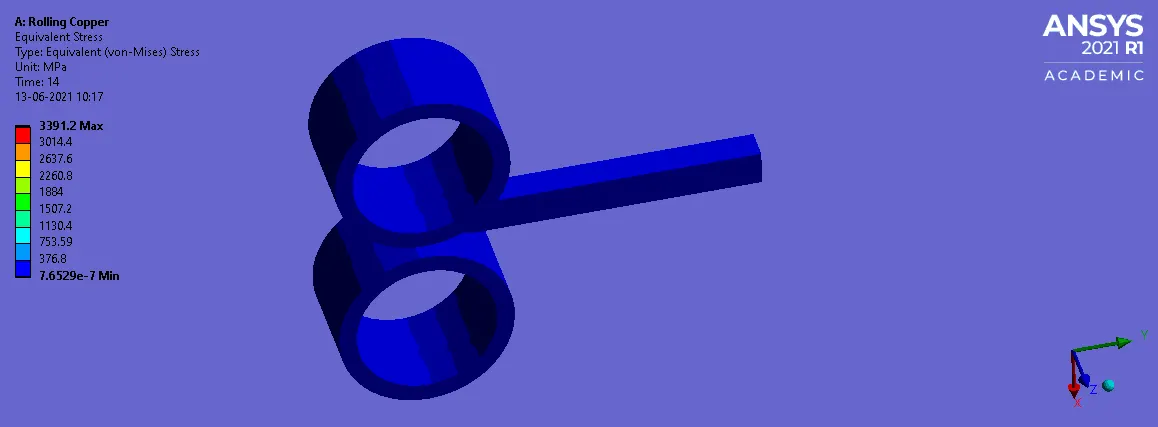
Fig 18: Equivalent Stress
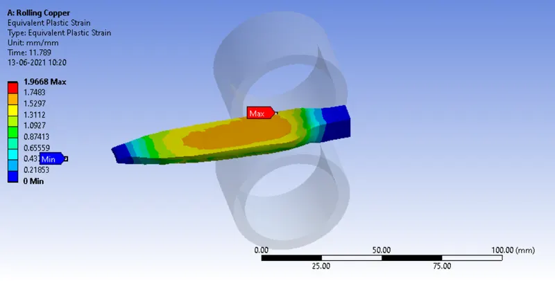
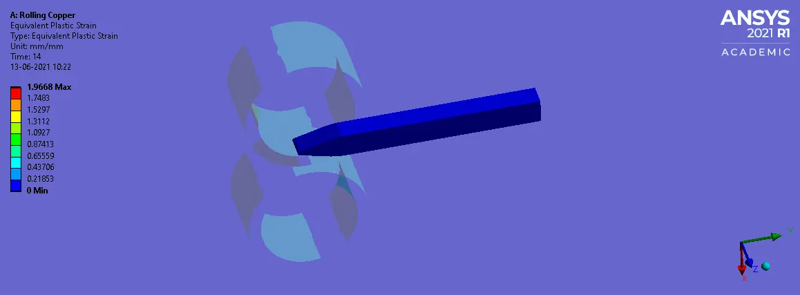
Fig 20: Equivalent Plastic Strain
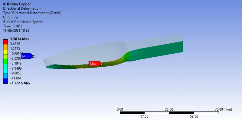
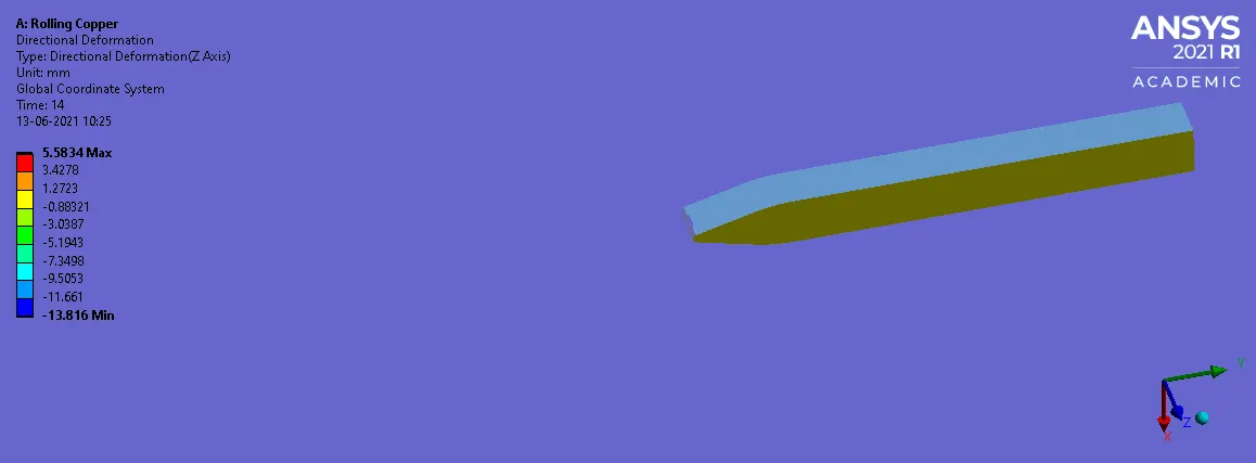
FIG:19 DIRECTIONAL DEFORMATION (Z-Axis)
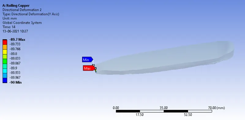
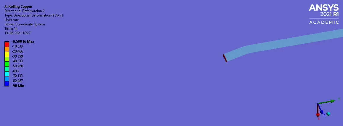
FIG:20 DIRECTIONAL DEFORMATION (Y-Axis)
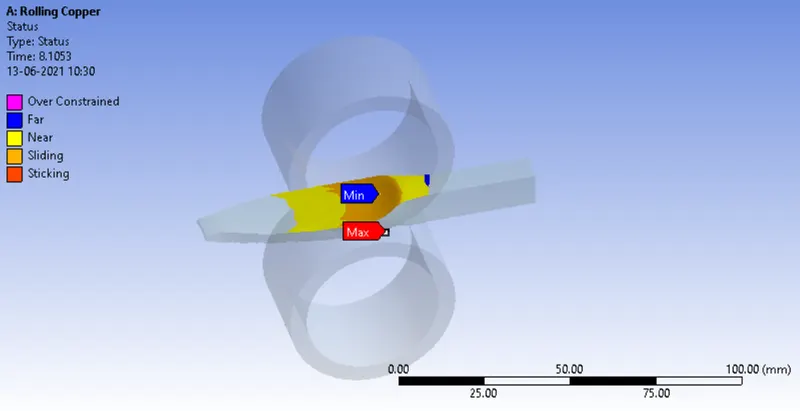
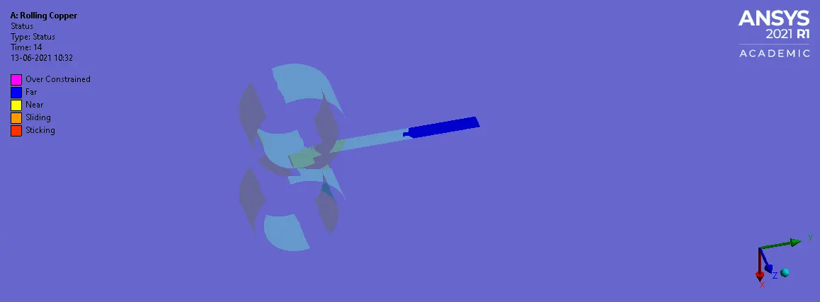
Fig:21 Status of the copper rolling
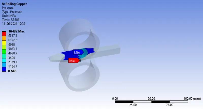
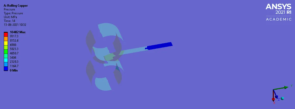
Fig:22 Pressure of the copper rolling
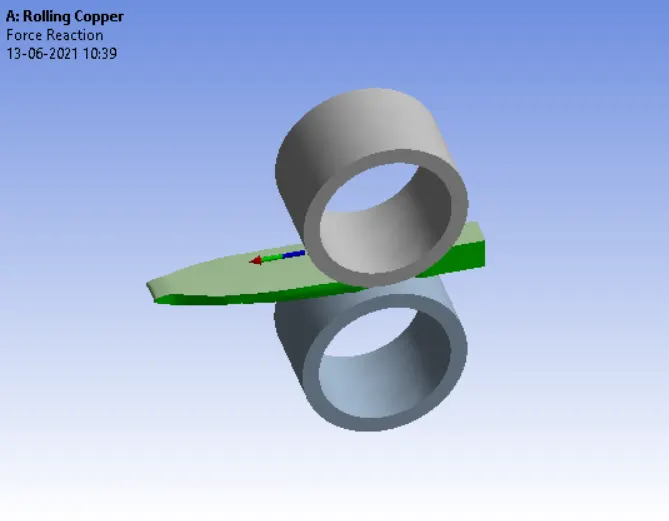
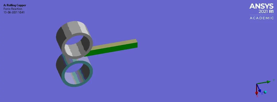
Fig:23 Force Reaction of the copper rolling
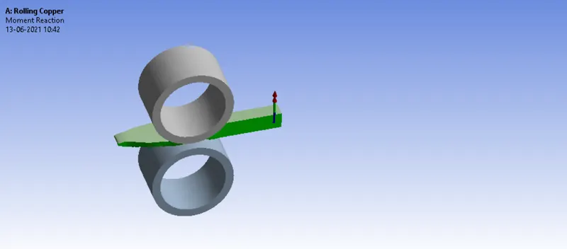
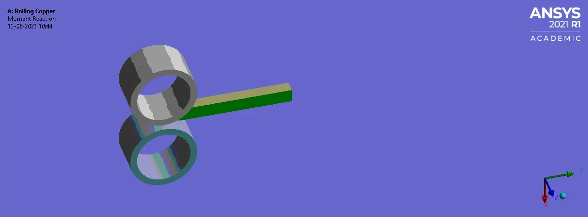
Fig:23 Moment Reaction of the copper rolling
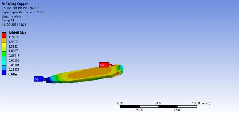
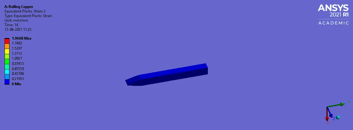
Fig:24 Equivalent Plastic Strain of Workpiece
Tabulated Result:
| Material |
Equivalent Stress (MPa) |
Equivalent Plastic Strain |
Directional Deformation (Z-Axis) (mm) |
Directional Deformation (Y-axis) |
Pressure (MPa) |
| Copper |
MAX: 3391.2 MIN: 7.6529e-7 |
MAX: 1.9668 MIN: 0 |
MAX: 5.5834 MIN: -13.816 |
MAX: -0.59916 MIN: -90 |
MAX: 10482 MIN: 0 |
The above tabular data shows the equivalent stress, Equivalent Plastic Strain, directional deformation (Z-Axis), directional deformation (Y-Axis), and Pressure(MPa) of the Copper Material. Copper experiences a maximum equivalent stress of 3391.2 MPa, for the whole body, Equivalent Plastic strain for the workpiece is 1.9668, Maximum Directional Deformation in the Z axis for the workpiece is 5.5834mm, we has Proved that the workpiece has displaced by 90mm by assigning the displacement value randomly, upto -90mm.
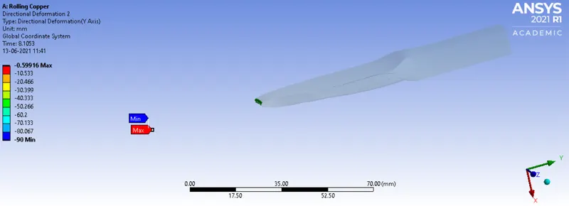
Fig:25 The workpiece is displaced by -90mm
CONCLUSION:
From the above result we can conclude that the equivalent stress of Copper is 3391.2MPa and this value is appropriate as it is followed by a grid dependency test. The workpiece has displaced by 90mm is proved by adding a random value to the displacement, upto 90mm and the tip of the workpiece is choosen as Geometry and by the directional deformation the workpiece is displaced by 90mm as shown in above figure.
LINK: https://drive.google.com/drive/folders/1NS6TlrfQH_7MHeo_WionZrH4nOHUgGGZ?usp=sharing