Week 5 Bending of iPhone
Bending of iPhone
OBJECTIVE: The objective of this challenge is to perform a static structural analysis and to Simulate the bending of iPhone as per the given cases below and to obtain the directional deformation for the model, Factor of Aluminium Alloy NL and Life of the Aluminium alloy for the case. Case 1: To Simulate the model as it is given in the video Case 2: To Move the bottom fingers from their defined position to the given position X= 22.5mm & Z= 10mm and obtain the results for the simulation. Also to define the S-N curve for the Aluminium Alloy material as per values given below and to determine the fatigue life results for the same.
| Stress, MPa | Number of Cycles, N |
| 225 | 10000 |
| 175 | 100000 |
| 143 | 1000000 |
| 110 | 10000000 |
| 80 | 100000000 |
SOFTWARE USED: ANSYS Workbench 2021 R1 and ANSYS Mechanical for Analysis.
INTRODUCTION:
Fig.1: Bending of iphone
It's just that under a particular type of flexing, the phone is prone to bend mainly because a metal insert meant to reinforce instead spins in an axis too close to the critical point. If they were further apart allowing better support to counter the flexing and not spinning, it would make it more resistant.
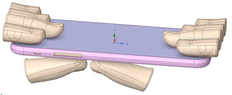
Fig.2: CAD Model of i phone with fingers
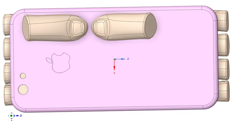
Fig.3: CAD Model of i phone with fingers
CASE-1:
PROCEDURE:
1. Open the ANSYS Workbench software. Under the Analysis system select the Static structural and wait for few seconds to pop up the window, which contains Engineering data, Geometry, Model, setup, Solution and Results.
2. Rename the static structural as i Phone bending.
3. Under geometry import the i Phone bending model. Edit the model by importing it into spaceclaim, if any abnormality found.
4. Update the model by right click and edit the Model for Preprocessing.
5. Wait for few seconds and ANSYS Mechanical will open as shown below.
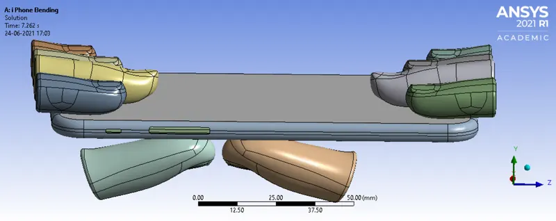
Fig.4: Model of i phone with fingers
6. Under Geometry rename its parts as Display, Frame, Inside, Pushing Fingers and fingers and Assign the material to the model. Assign Structural Steel for all fingers, Assign glass material to the display, Aluminum alloy to the frame, and assign polyethylene to the inside.
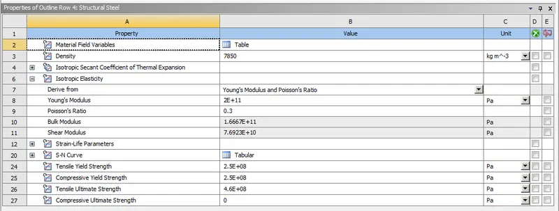
FIG 5: Material properties of a Structural Steel
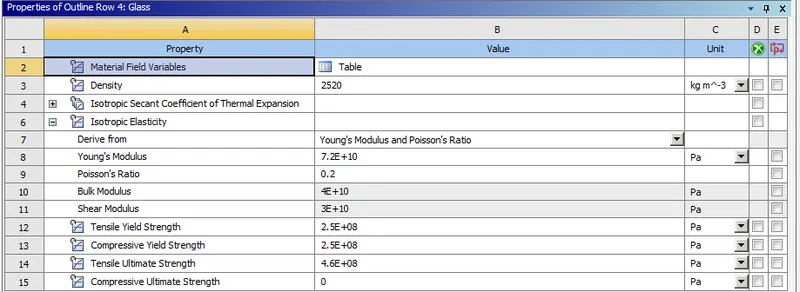
FIG 6: Material properties of a Glass
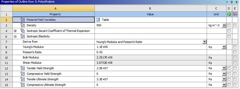
FIG 7: Material properties of a Polyethylene
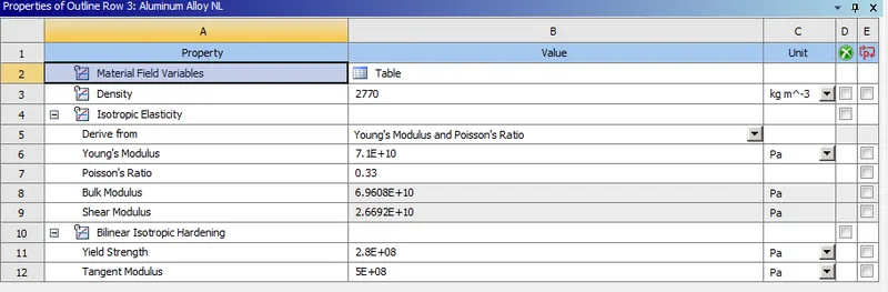
FIG 8: Material properties of a Aluminum Alloy NL
The fingers above the phone are used to hold the phone as well to act as rigid when the force from the down finger is given. So make all the fingers as rigid expect the thumb fingers.
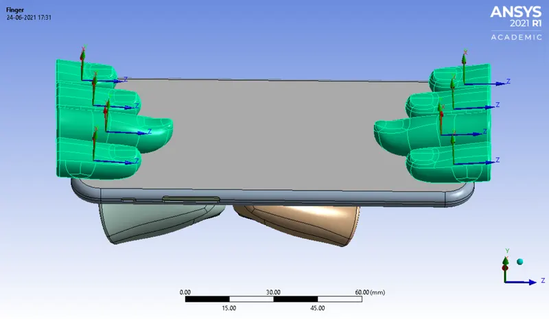
Fig.9: Making fingers as rigid
7. Define the contacts, so delete the contacts which is indicated by question mark, and expect Display to frame remaining all make the contact as frictional less, and a Bonded contact between the Display to frame is Defined.
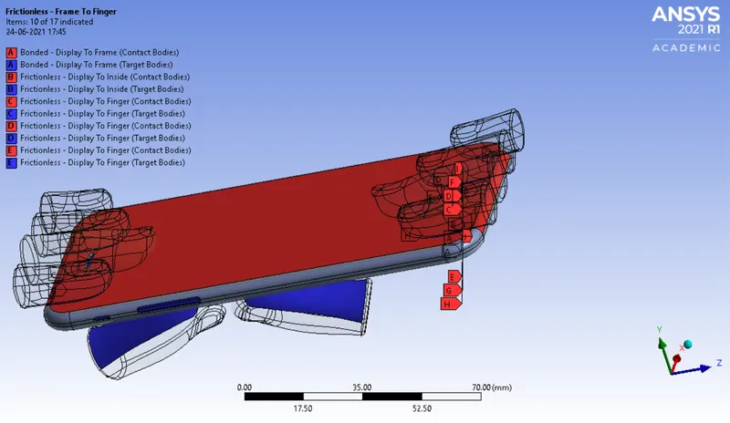
Fig.10: Bonded anf frictionless contact between the different parts
8. Insert a fixed Joints for the Fingers by right clicking on connections and insert joint. Change Connection type as body to ground, type as fixed and select the respective faces of fingers for scope.
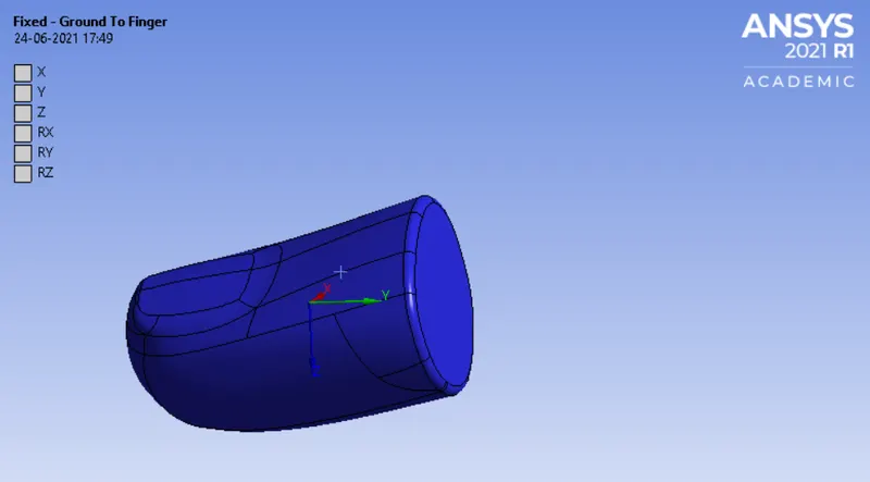
Fig.11: Fixed joint
Follow the same procedure for remaining fingers
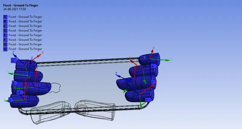
Fig.12: Fixed joint for all fingers
Insert a translational Joints for the pushing Fingers by right clicking on connections and insert joint. Change Connection type as body to ground, type as translational and select the respective faces of pushing fingers for scope. Make sure that the x-axis facing upwards for both the pushing fingers.
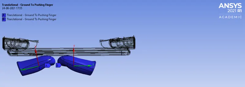
Fig.13:Translational joint for all fingers
9. In ANSYS automatic mesh will be performed with Default mesh size and change the mesh size as 2mm. for the parts as shown in figure(i.e Ansys student version will have a limted number of elements and nodes.) This size is selected by grid dependency test. beyond this size will crosses the student version limit.
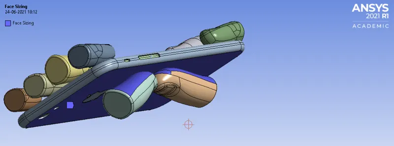
Fig.14: Selecting faces for meshing
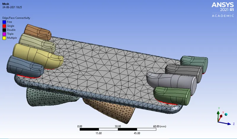
Fig.15 Meshing of an i Phone
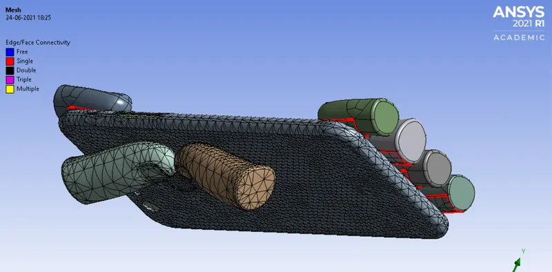
Fig.16 Meshing of an i Phone
Be aware of ANSYS Student Edition and don't go beyond the size limit. The below figure shows the mesh size along with its number of nodes and elements.
10. Analysis settings Change no. of steps as 8, Solver type as Direct, weak spring as program controlled, large deflection on, non linear stabilization as constant, energy disipation as 0.1, activation for first substep as yes and output control all as yes.
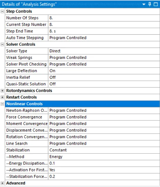
FIG 17: Analysis settings
Make the inside part of the i phone as fixed by using fixed support as shown below. So that when the load is applied the phone cannot fly from its position.
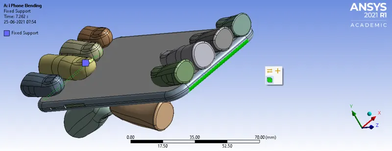
Fig.18: Fixed Support
Similarly the displacement of frame should be only in Y-axis, so use displacement option and select the faces as shown below and make x=0 and z=0.
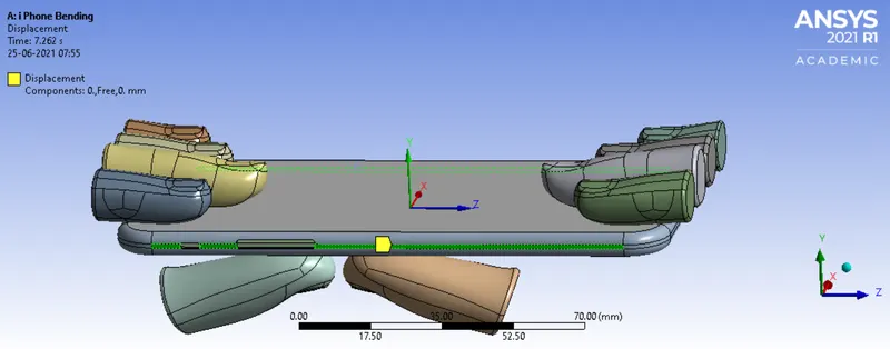
Fig.19: Displacement
Apply joint load for the pushing fingers as shown below and apply a magnitude of 0,2,4,6,8,6,4,2,0. And type as displacement.
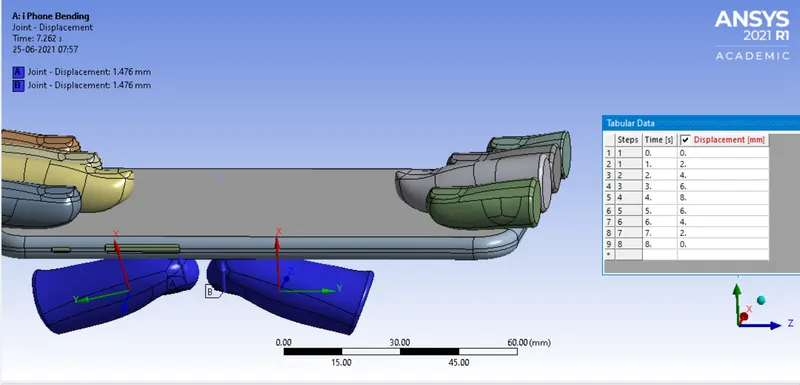
Fig.20: Joint load
11. Now request for the outputs such as equivalent stress, equivalent elastic strain, directional deformation, Force reaction, Factor of Aluminium Alloy NL, Life of the Aluminium alloy and contact Tool.
12. SOLVE the solution and we can see the simulation run under soluion information.
Fig.21: solver output
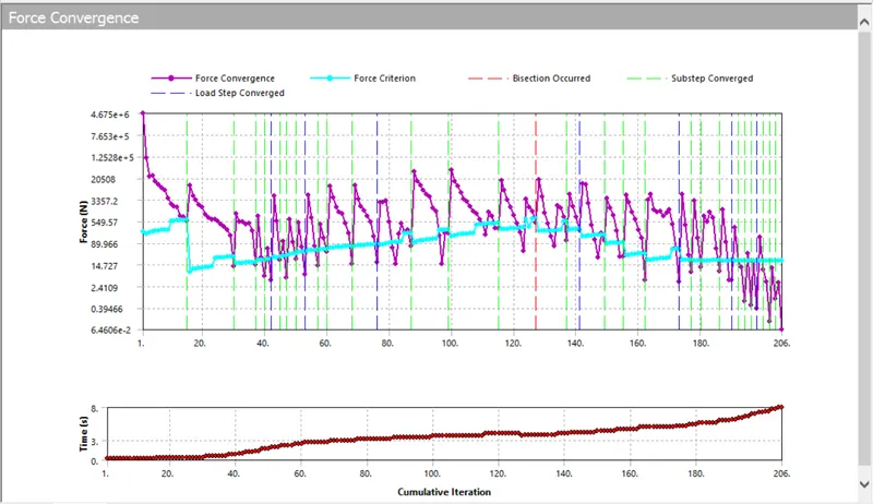
Fig.22: Force convergence
CASE-2: Changing the positions of pushing fingers.
Import the model into ansys spaceclaim and by using the move option change the positions of pushing finger byX= 22.5mm and Z= 10mm for both the pushing fingers.
Fig.23 Initial position
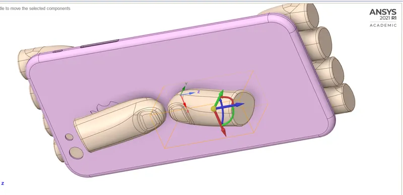
Fig.24 Moving pushing fingers for respected position
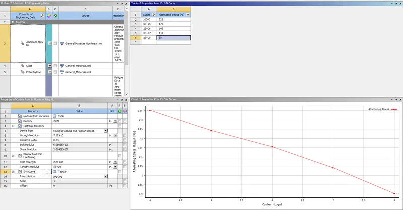
Fig.25: Representing the S-N Curve for the aluminum alloy
Remaining all follow the same procedure as mentioned in case-1.
RESULT:
Simulation results for the bending of i phone for case-1
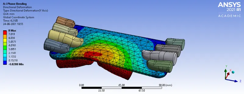
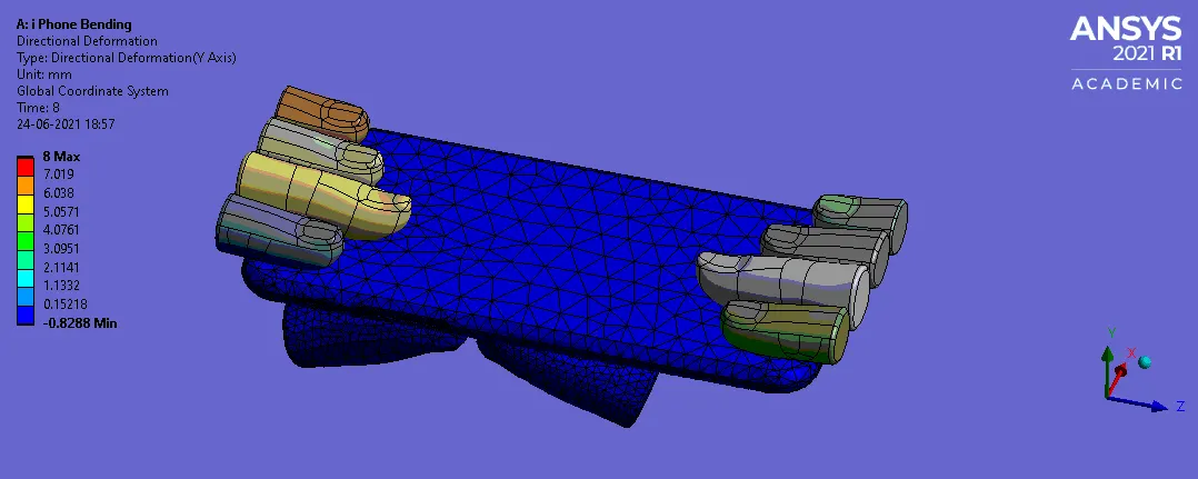
FIG:26 DIRECTIONAL DEFORMATION (Y-Axis)
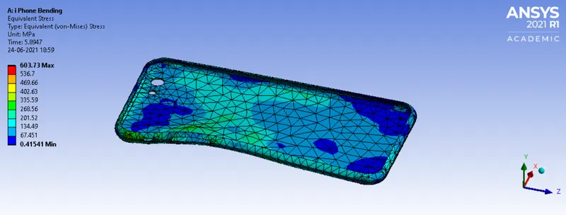
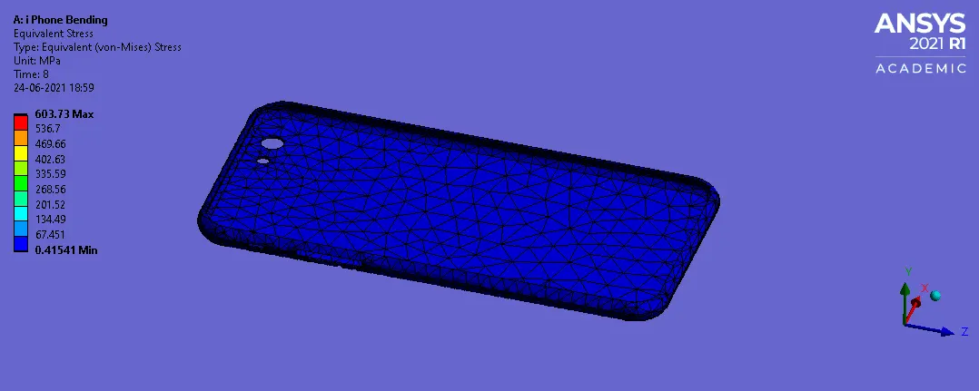
Fig 27: Equivalent Stress of a frame
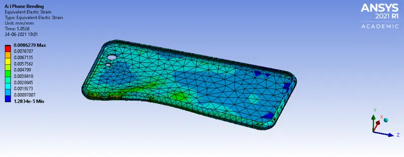
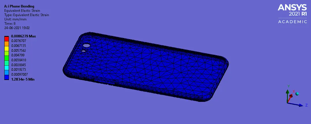
Fig 28: Equivalent Elastic Strain of a frame
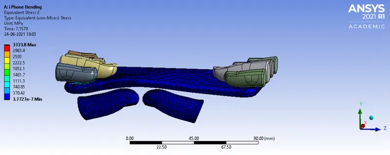
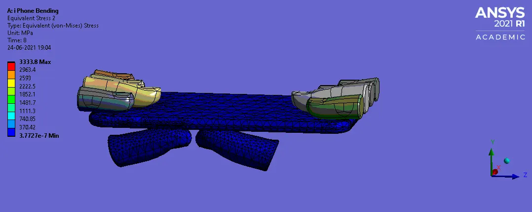
Fig 29: Equivalent Stress of a iphone
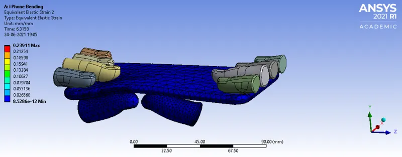
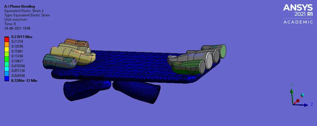
Fig 30: Equivalent Elastic Strain of a i phone
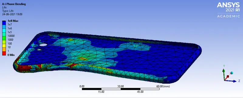
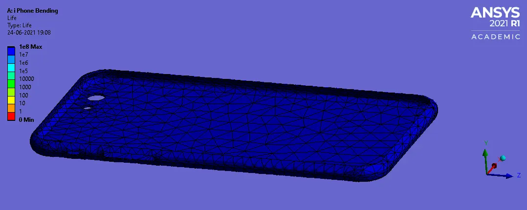
Fig 31: Life of an Aluminum alloy
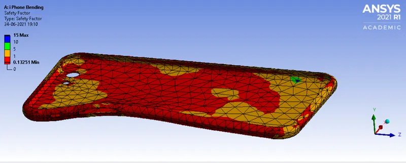
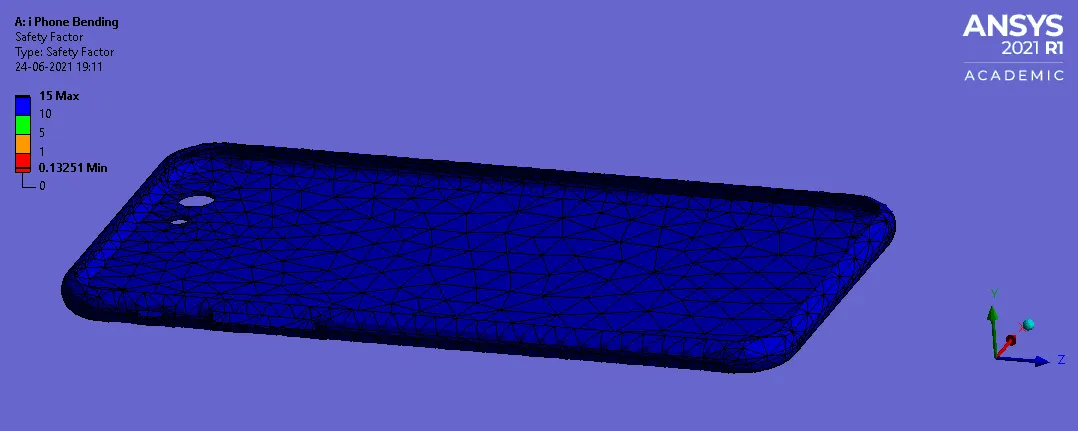
Fig 32: Safety factor of an Aluminum alloy
Simulation results for the bending of i phone for case-2
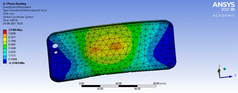
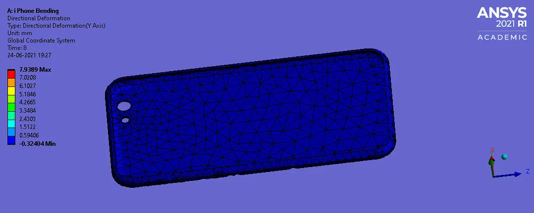
FIG:33 DIRECTIONAL DEFORMATION (Y-Axis)
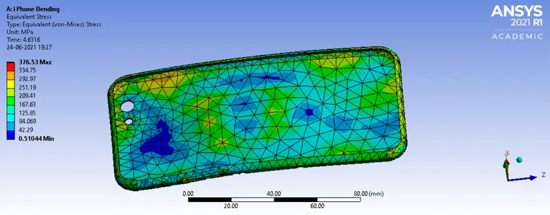
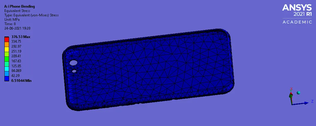
Fig 34: Equivalent Stress of a frame
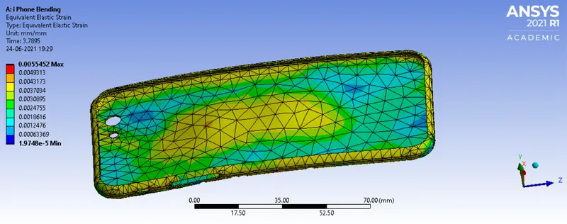
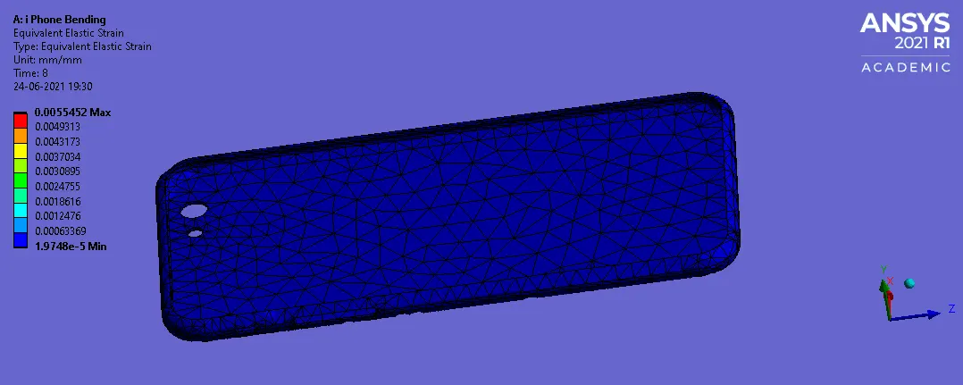
Fig 35: Equivalent Elastic Strain of a frame
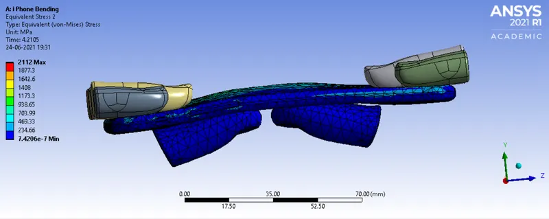
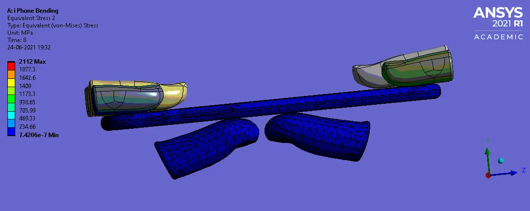
Fig 36: Equivalent Stress of a iphone
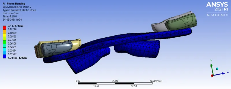
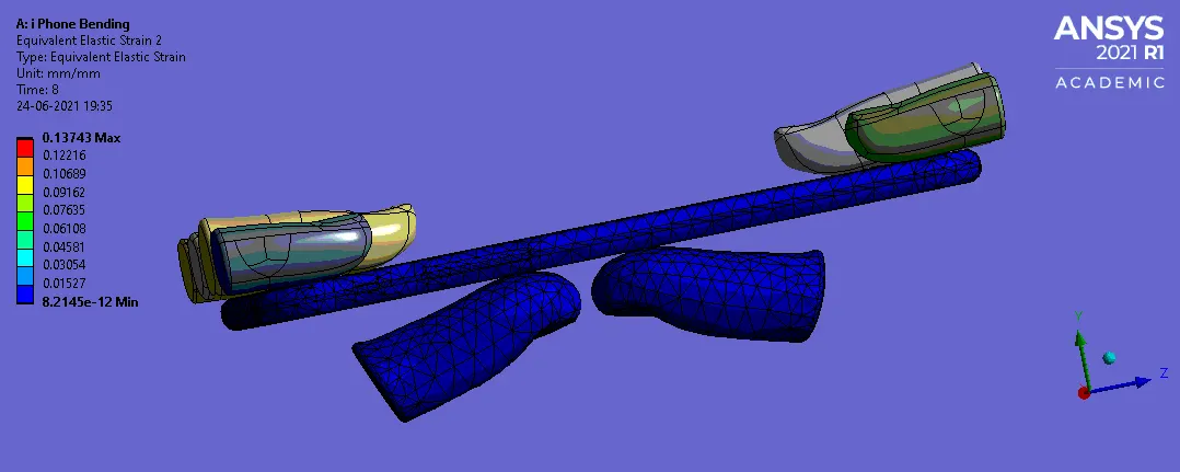
Fig 37: Equivalent Elastic Strain of a i phone
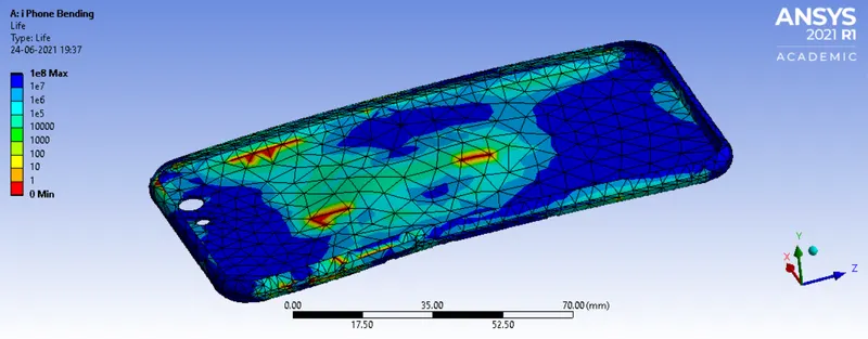
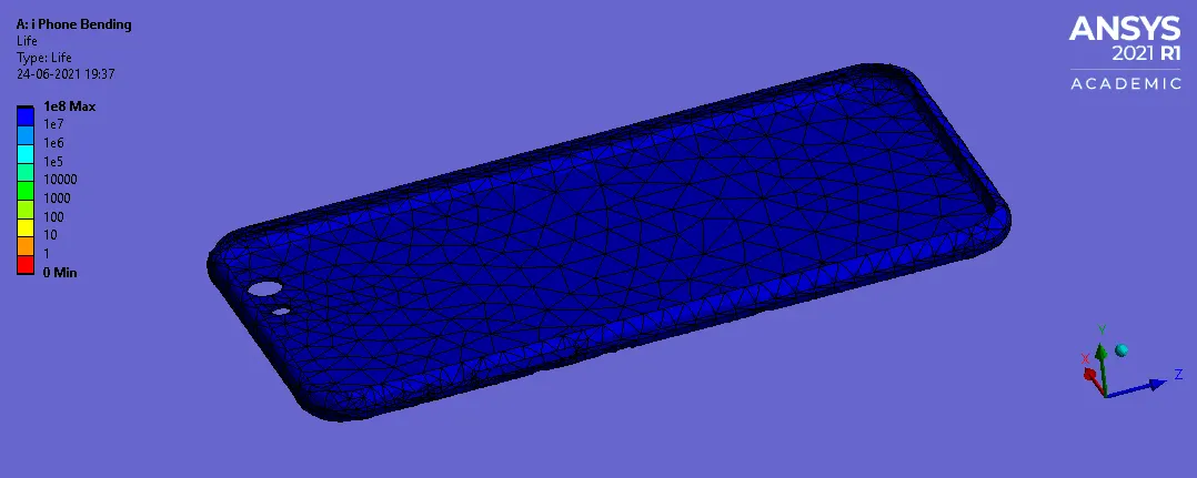
Fig 38: Life of an Aluminum alloy
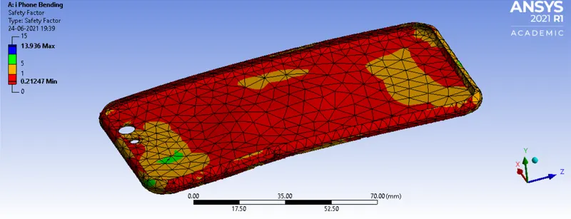
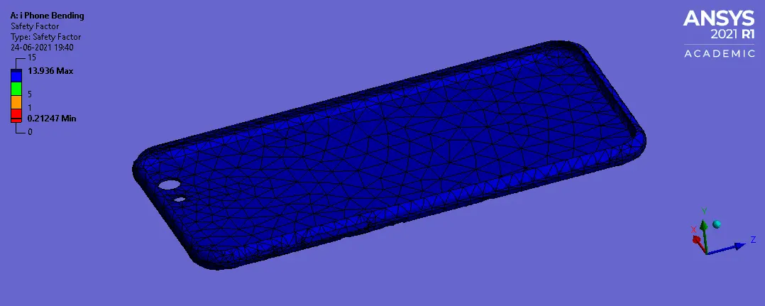
Fig 39: Safety factor of an Aluminum alloy
GRAPH FOR CASE-1
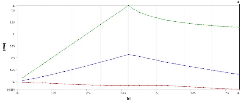
Fig.40: Directional deformation in Y-direction
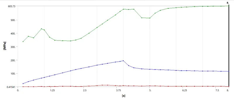
Fig.41: Equivalent stress in frame
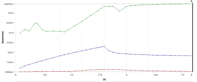
Fig.42: Equivalent elastic strain in frame
GRAPH FOR CASE-2
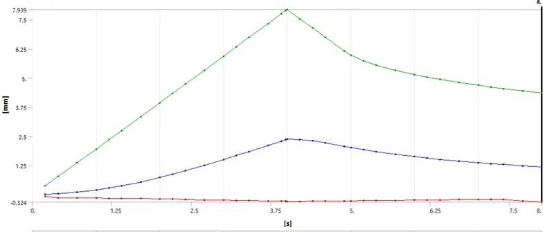
Fig.43: Directional deformation in Y-direction
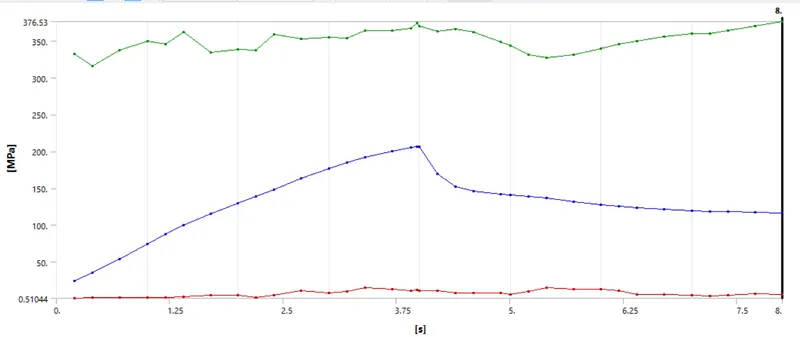
Fig.44: Equivalent stress in frame
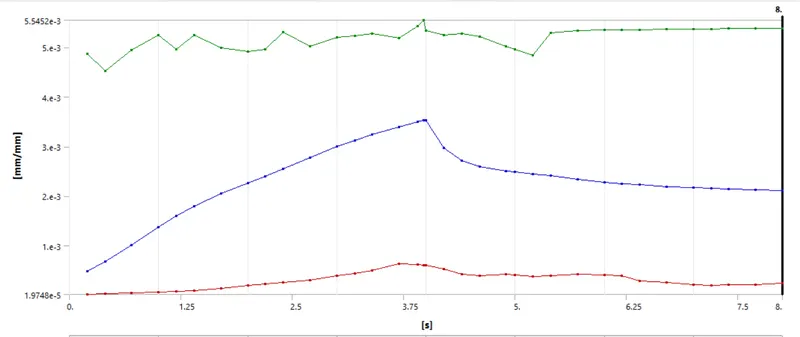
Fig.45: Equivalent elastic strain in frame
Tabulated Result:
| CASES | Directional deformation (Y-Axis) (mm) | Equivalent stress of a frame (MPa) | Equivalent elastic strain of a frame | Equivalent stress (MPa) | Equivalent elastic strain | Life of an aluminum alloy | Safety factor of an aluminum alloy |
| 1. |
Max: 8 Min: -0.8288 |
Max: 603.73 Min: 0.41541 |
Max: 0.0086279 Min: 1.2834^-5 |
Max: 3333.8 Min: 3.7727^-7 |
Max: 0.23911 Min: 8.5286^-12 |
Max: 1e^8 Min: 0 |
Max: 15 Min: 0.13251 |
| 2. |
Max: 7.9389 Min: -0.32404 |
Max: 376.53 Min: 0.51044 |
Max: 0.0055452 Min: 1.9748e^-5 |
Max: 2112 Min: 7.4206e^-7 |
Max: 0.13743 Min: 8.2145e^-12 |
Max: 1e^8 Min: 0 |
Max: 13.936 Min: 0.21247 |
CONCLUSION:
From the above table we conclude that the case-1 will have maximum equivalent stress of a frame than that of case-2. As well as the equivalent elastic strain is maximum at case-1 when compared to case-2. The maximum directional deformation of 8mm is encounted in case-1, and the maximum directional deformation of 7.9389mm is encounted in case-2, which is almost nearer to each other. The life of an aluminum alloy is 1e^8 is correct as in our cycle it is the maximum value, which we have mentioned in S-N Curve. The Safety factor in both cases is below 1, which will consider as failure of material. Further optimization have to done in order to make the material to Pass.
LINK: https://drive.google.com/drive/folders/1dMMlj8DI2Z1NrJ_qlCE2iBDuwvW_sm8O?usp=sharing