Assembly of Yacht
1.MODELLING OF A SUNSEEKER PREDATOR YACHT
1.OBJECTIVE:
The main objective of performing this modelling is to produce a detailed model of different parts of a SUNSEEKER PREDATOR YACHT, as well as assigning Decals, paint to the model.
The other objective is to assemble the different parts of a SUNSEEKER PREDATOR YACHT, which is produced by us. After assembly we have to render the model with proper appearance and environment.
2.INTRODUCTION:
The SOLIDWORKS CAD software is a mechanical design automation application that lets designers quickly sketch out ideas, experiment with features and dimensions, and produce models and detailed drawings.
SOLIDWORKS uses a 3D design approach. As we can design a part, from the initial sketch to the final result, we can create a 3D model. From this model, we can create 2D drawings or mate components consisting of parts or subassemblies to create 3D assemblies. We can also create 2D drawings of 3D assemblies. When designing a model using SOLIDWORKS, we can visualize it in three dimensions, the way the model exists once it is manufactured.
In this report we had discussed about the modelling, assembling and rendering of SUNSEEKER PREDATOR YACHT and included with tools which are used to model the YACHT as well as the quick explanation of each parts.
DESIGN METHODOLOGY:
DESCRIPTION:
You might hear a yacht referred to as a boat, but not all boats are yachts. A yacht is technically a boat, because it is a vessel that floats on the water. But to be called a yacht, a boat has to be at least 35 feet long. Yachts can also be much larger than that: A mega-yacht is more than 100 feet long, while yachts more than 200 feet long are called super-yachts. Yachts are usually used for recreation, and they are designed to be luxurious. These types of boats often have powerful motors that allow them to easily travel long distances, but they may be traditional sailing yachts powered by the wind. Other kinds of boats include fishing boats, which are boats built to be durable enough to withstand hours of fishing in either fresh or salt water, and rowboats, small boats often used in shallow water that are typically designed to be propelled with oars. However, no matter which type of boat you’re on, you’re likely to encounter some of the same features and terminology.
The following are the major parts of a SUNSEEKER PREDATOR YACHT.
Anchor: The anchor is a heavy object that drops down into the water to keep a boat or yacht from moving.
Beam: The beam is the widest point of a boat or yacht.
Berth: The sleeping area of a yacht is the berth.
Bow: The front of the yacht’s hull is the bow.
Cabin: Private rooms and living compartments in a yacht are called cabins.
Deck: The part of the yacht where you can walk around outside is called the deck.
Draft: The draft is the minimum depth of water needed for a boat to float.
Hull: The hull is the part of a yacht or boat that floats in the water. A hull has framework inside it and a hard outer shell that you can see.
Keel: The keel is the part of the hull that runs down the middle from the bow to the stern. The keel is considered the foundation or backbone of a boat.
Porthole: Windows in a yacht or boat are called portholes.
Propellers: A motorized yacht has blades that spin fast, called propellers, that make it move through the water.
Stern: The back of the yacht’s hull is the stern.
PARTS EXPLANATION:
MODELLING OF PROPELLER:
A motorized yacht has blades that spin fast, called propellers, that make it move through the water.
Base Feature
The Base feature requires:
Sketch plane –Right plane, Top plane, reference plane
Sketch profile –Line, circle, Spline, Corner Rectangle.
Feature type –Revolve, Solid loft, Extruded boss, Fillet, extrude cut, circular pattern.
Reference plane
We can create planes in part or assembly documents. We can use planes to sketch, to create a section view of a model, for a neutral plane in a draft feature, and so on.
Line
Click Line on the Sketch toolbar, or click Tools > Sketch Entities > Line. Draw the line based on the requirement of sketch. As well as by using this command we can draw horizontal line, vertical line, centre line, etc.
Circle is sketching tool in SolidWorks. There are two methods of drawing circles, Center Circle and Perimeter Circle. Center circle sketches center-based circles. ... This type of circles are used when we have to create a circle passing through three points, we have to specify all three points to create this circle.
Spline
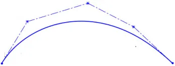
The SOLIDWORKS software supports two types of splines, B-splines and style splines.
We can use B-splines to create complex curves. You can define and modify them using several controls, including spline points, spline handles, and control polygons. A single B-spline can have multiple through points and spans (the region between through points). You can apply curvature constraints at each endpoint. At each through point, you can weigh the tangency vector and control the tangency direction.

Style splines, based on Bézier curves, are a good option when it is important to have a smooth curve (that is, to assure curvature continuity). You define and control the curves using control vertices. The control vertices form a control polygon, or hull of the curve. There are no through points, so a style spline has only one span between the endpoints. You can inference style splines for tangency or equal curvature. You can constrain the points and dimension the curves' sides. These curves also support mirroring and self-symmetry.
Corner Rectangle
- Menu. Click Tools > Sketch Entities to select rectangle tools.
- Rectangle PropertyManager. Change to different rectangle tools from the Rectangle PropertyManager, and draw the required sketch.

Extruded boss:An Extruded Boss/Base feature will allow us to take a 2D sketch and add thickness to it in the third dimension. Every few releases, this feature gets some terrific functionality added to it.
Revolve: creates a feature or new solid body by rotating one or more sketched profiles around an axis. The first feature is the base feature. If we create an assembly feature, only the solid output and cut operations are supported. Revolved assembly features can cut through other parts.
Lofts. Loft creates a feature by making transitions between profiles. A loft can be a base, boss, cut, or surface. we create a loft using two or more profiles. ... For a solid loft, the first and last profiles must be model faces or faces created by split lines, planar profiles, or surfaces.
Fillet Overview. Fillet/Round creates a rounded internal or external face on the part. We can fillet all edges of a face, selected sets of faces, selected edges, or edge loops.
Extrude cut: The Extruded cut operation allows us to easily remove material from a solid by extruding a profile along the normal to its plane.
Circular Patterns. Use circular patterns to create multiple instances of one or more features that we can space uniformly around an axis. Pattern instances inherit the feature color of the original feature when the: Pattern is based on one feature.
FIG PROPELLER
RADAR:
THE FOLLOWING ARE THE TOOLS AND FEATURES USED TO MODEL THE RADAR.
Base Feature
The Base feature requires:
Sketch plane –Right plane, Top plane, reference plane
Sketch profile –Line, circle, offset, polygon,
Feature type – Extruded boss, Fillet, extrude cut, sketch driven pattern.
Line
Click Line on the Sketch toolbar, or click Tools > Sketch Entities > Line. Draw the line based on the requirement of sketch. As well as by using this command we can draw horizontal line, vertical line, centre line, etc.
Circle is sketching tool in SolidWorks. There are two methods of drawing circles, Center Circle and Perimeter Circle. Center circle sketches center-based circles. ... This type of circles are used when we have to create a circle passing through three points, we have to specify all three points to create this circle.
Offset Entities. Offset one or more sketch entities, selected model edges, or model faces by a specified distance. For example, we can offset sketch entities such as splines or arcs, sets of model edges, loops, and so on.
Polygons. Create equilateral polygons with any number of sides between 3 and 40. To create a polygon: Click Polygon on the Sketch toolbar, or click Tools, Sketch Entities, Polygon.
Extruded boss:An Extruded Boss/Base feature will allow us to take a 2D sketch and add thickness to it in the third dimension. Every few releases, this feature gets some terrific functionality added to it.
Fillet Overview. Fillet/Round creates a rounded internal or external face on the part. We can fillet all edges of a face, selected sets of faces, selected edges, or edge loops.
Extrude cut: The Extruded cut operation allows us to easily remove material from a solid by extruding a profile along the normal to its plane.
The sketch driven pattern creates copies of existing features and places them wherever you've added a point in a sketch. It's that simple. All it takes is a sketch created specifically to place instances of a feature. This offers a great amount of flexibility in terms of placing the features.
FIG RADAR
HULL:
THE FOLLOWING ARE THE TOOLS AND FEATURES USED TO MODEL THE HULL.
Reference plane
We can create planes in part or assembly documents. We can use planes to sketch, to create a section view of a model, for a neutral plane in a draft feature, and so on.
Line
Click Line on the Sketch toolbar, or click Tools > Sketch Entities > Line. Draw the line based on the requirement of sketch. As well as by using this command we can draw horizontal line, vertical line, centre line, etc.
Circle is sketching tool in SolidWorks. There are two methods of drawing circles, Center Circle and Perimeter Circle. Center circle sketches center-based circles. ... This type of circles are used when we have to create a circle passing through three points, we have to specify all three points to create this circle.
Spline
The SOLIDWORKS software supports two types of splines, B-splines and style splines.
We can use B-splines to create complex curves. You can define and modify them using several controls, including spline points, spline handles, and control polygons. A single B-spline can have multiple through points and spans (the region between through points). You can apply curvature constraints at each endpoint. At each through point, you can weigh the tangency vector and control the tangency direction.
Style splines, based on Bézier curves, are a good option when it is important to have a smooth curve (that is, to assure curvature continuity). You define and control the curves using control vertices. The control vertices form a control polygon, or hull of the curve. There are no through points, so a style spline has only one span between the endpoints. You can inference style splines for tangency or equal curvature. You can constrain the points and dimension the curves' sides. These curves also support mirroring and self-symmetry.
Corner Rectangle
- Menu. Click Tools > Sketch Entities to select rectangle tools.
- Rectangle PropertyManager. Change to different rectangle tools from the Rectangle PropertyManager, and draw the required sketch.
TRIM:
We can use Power trim to trim multiple, adjacent sketch entities by dragging the pointer across each sketch entity. To trim with the Power trim option: Right-click the sketch and select Edit Sketch. ... Continue to hold down the pointer and drag across each sketch entity we want to trim.
Linear Patterns. Use linear patterns to create multiple instances of one or more features that we can space uniformly along one or two linear paths. ... To create a linear pattern: Create one or more features to replicate. Click Linear Pattern (Features toolbar) or Insert > Pattern/Mirror > Linear Pattern.
Slot tools:
- Sketch tab. Click the Slot CommandManager, to select slot tools from the Slot
 flyout tool.
 - Menu. Click Tools > Sketch Entities to select slot tools
- Slot PropertyManager. Change slot tools in the Slot PropertyManager.
Offset Entities.
Offset one or more sketch entities, selected model edges, or model faces by a specified distance. For example, We can offset sketch entities such as splines or arcs, sets of model edges, loops, and so on.
- Click Ellipse. on the Sketch toolbar or Tools > Sketch Entities > Ellipse. ...
- Click in the graphics area to place the center of the ellipse.
- Drag and click to set the major axis of the ellipse.
- Drag and click again to set the minor axis of the ellipse. Video: Sketching an Ellipse.
Extruded boss:An Extruded Boss/Base feature will allow us to take a 2D sketch and add thickness to it in the third dimension. Every few releases, this feature gets some terrific functionality added to it.
Revolve: creates a feature or new solid body by rotating one or more sketched profiles around an axis. The first feature is the base feature. If we create an assembly feature, only the solid output and cut operations are supported. Revolved assembly features can cut through other parts.
Lofts. Loft creates a feature by making transitions between profiles. A loft can be a base, boss, cut, or surface. we create a loft using two or more profiles. ... For a solid loft, the first and last profiles must be model faces or faces created by split lines, planar profiles, or surfaces.
Fillet Overview. Fillet/Round creates a rounded internal or external face on the part. We can fillet all edges of a face, selected sets of faces, selected edges, or edge loops.
Extrude cut: The Extruded cut operation allows us to easily remove material from a solid by extruding a profile along the normal to its plane.
Circular Patterns. Use circular patterns to create multiple instances of one or more features that we can space uniformly around an axis. Pattern instances inherit the feature color of the original feature when the: Pattern is based on one feature.
Champer:
The chamfer tool creates a beveled feature on selected edges, faces, or a vertex. ... Set the Distance and Angle in the Chamfer PropertyManager or in the graphics area. A manipulator arrow appears that points in the direction in which the distance is measured.
Dome:
Click Dome on the Features toolbar, or click Insert > Features > Dome. Select one or more planar or non-planar faces. Set a value for the distance by which the dome expands. Click to create a concave dome (default is convex).
Solid sweep:
Solid sweep is a tool that creates a solid, a cut or a surface feature by moving a profile along a path. To create a solid, use the Swept Boss tool to move a profile along a path. The profile can contain one or more closed contours.
Projected Curve:
A projected curve is typically used either in sweeps and lofts as path or guide curve. There are two types of projected curves: Sketch on Sketch: Use two sketches to make a single curve. Sketch on surface: Use a sketch to project on a surface.
Trim Surface.
We can use a surface, plane, or sketch as a trim tool to trim intersecting surfaces. We can also use a surface in conjunction with additional surfaces, as mutual trim tools. ... Trims surfaces using surfaces, sketch entities, curves, planes, and so on.
We can create extruded surfaces from models that include 2D or 3D faces and knit the extruded surfaces to surrounding features. Click Insert > Surface > Extrude. ... To extrude from a 3D face, select a 3D face.
Knit Surface.
Use the Knit Surface tool to combine two or more faces and surfaces into one. ... Knit surfaces absorb the surface bodies you used to create them. Create a solid body when the knit surfaces form a closed volume, or leave as a surface body. Select Merge entities to merge faces with the same underlying geometry ...
Filled Surface.
The Filled Surface feature constructs a surface patch with any number of sides, within a boundary defined by existing model edges, sketches, or curves, including composite curves. We can use this feature to construct a surface to fill a gap in a model.
Shells.
The shell tool hollows out a part, leaves open the faces you select, and creates thin-walled features on the remaining faces. If we do not select any face on the model, we can shell a solid part, creating a closed, hollow model. we can also shell a model using multiple thicknesses.
Delete Face
Delete Face Feature' allows the user to efficiently remove faces by maintaining multi-selection facility. There are many options available within the delete feature – Delete, Delete and Patch, and Delete and Fill.
Thin Feature in SolidWorks.
Thin features are usually open sketches which can be extruded in both directions. Below we will see this feature in Extruded Boss/Base and Revolved Boss/Base command located on the Feature toolbar.
MIRROR:
The Mirror Part command inside SOLIDWORKS creates a mirrored version of an existing part. This is a good way to create a left-hand version and a right-hand version of a part.
Extruded cut:
The Extruded cut operation allows us to easily remove material from a solid by extruding a profile along the normal to its plane.
- In the Task Pane, select the Appearances, Scenes, and Decals tab.
- Expand Decals and select the decals folder or a folder containing custom decals.
- In the lower pane, identify the decal to apply and do one of the following: Drag the decal to an entity of the model, such as a face or surface.
FIG HULL
GARAGE DOOR:
THE FOLLOWING ARE THE TOOLS AND FEATURES USED TO MODEL THE GARAGE DOOR.
Reference plane
We can create planes in part or assembly documents. We can use planes to sketch, to create a section view of a model, for a neutral plane in a draft feature, and so on.
Line
Click Line on the Sketch toolbar, or click Tools > Sketch Entities > Line. Draw the line based on the requirement of sketch. As well as by using this command we can draw horizontal line, vertical line, centre line, etc.
Circle is sketching tool in SolidWorks. There are two methods of drawing circles, Center Circle and Perimeter Circle. Center circle sketches center-based circles. ... This type of circles are used when we have to create a circle passing through three points, we have to specify all three points to create this circle.
Extruded cut:
The Extruded cut operation allows us to easily remove material from a solid by extruding a profile along the normal to its plane.
Fillet Overview.
Fillet/Round creates a rounded internal or external face on the part. We can fillet all edges of a face, selected sets of faces, selected edges, or edge loops.
MIRROR:
The Mirror Part command inside SOLIDWORKS creates a mirrored version of an existing part. This is a good way to create a left-hand version and a right-hand version of a part.
Shells.
The shell tool hollows out a part, leaves open the faces you select, and creates thin-walled features on the remaining faces. If we do not select any face on the model, we can shell a solid part, creating a closed, hollow model. we can also shell a model using multiple thicknesses.
FIG GARAGE DOOR
MODELLING OF FRONT SEAT:
THE FOLLOWING ARE THE TOOLS AND FEATURES USED TO MODEL THE FRONT SEAT.
Line
Click Line on the Sketch toolbar, or click Tools > Sketch Entities > Line. Draw the line based on the requirement of sketch. As well as by using this command we can draw horizontal line, vertical line, centre line, etc.
Spline
The SOLIDWORKS software supports two types of splines, B-splines and style splines.
We can use B-splines to create complex curves. You can define and modify them using several controls, including spline points, spline handles, and control polygons. A single B-spline can have multiple through points and spans (the region between through points). You can apply curvature constraints at each endpoint. At each through point, you can weigh the tangency vector and control the tangency direction.
Style splines, based on Bézier curves, are a good option when it is important to have a smooth curve (that is, to assure curvature continuity). You define and control the curves using control vertices. The control vertices form a control polygon, or hull of the curve. There are no through points, so a style spline has only one span between the endpoints. You can inference style splines for tangency or equal curvature. You can constrain the points and dimension the curves' sides. These curves also support mirroring and self-symmetry.
Offset Entities.
Offset one or more sketch entities, selected model edges, or model faces by a specified distance. For example, We can offset sketch entities such as splines or arcs, sets of model edges, loops, and so on.
Solid sweep:
Solid sweep is a tool that creates a solid, a cut or a surface feature by moving a profile along a path. To create a solid, use the Swept Boss tool to move a profile along a path. The profile can contain one or more closed contours.
Knit Surface.
Use the Knit Surface tool to combine two or more faces and surfaces into one. ... Knit surfaces absorb the surface bodies you used to create them. Create a solid body when the knit surfaces form a closed volume, or leave as a surface body. Select Merge entities to merge faces with the same underlying geometry ...
Extruded boss:An Extruded Boss/Base feature will allow us to take a 2D sketch and add thickness to it in the third dimension. Every few releases, this feature gets some terrific functionality added to it.
Revolve: creates a feature or new solid body by rotating one or more sketched profiles around an axis. The first feature is the base feature. If we create an assembly feature, only the solid output and cut operations are supported. Revolved assembly features can cut through other parts.
Filled Surface.
The Filled Surface feature constructs a surface patch with any number of sides, within a boundary defined by existing model edges, sketches, or curves, including composite curves. We can use this feature to construct a surface to fill a gap in a model.
MIRROR:
The Mirror Part command inside SOLIDWORKS creates a mirrored version of an existing part. This is a good way to create a left-hand version and a right-hand version of a part.
Trim Surface.
We can use a surface, plane, or sketch as a trim tool to trim intersecting surfaces. We can also use a surface in conjunction with additional surfaces, as mutual trim tools. ... Trims surfaces using surfaces, sketch entities, curves, planes, and so on.
Extruded cut:
The Extruded cut operation allows us to easily remove material from a solid by extruding a profile along the normal to its plane.
Lofts. Loft creates a feature by making transitions between profiles. A loft can be a base, boss, cut, or surface. we create a loft using two or more profiles. ... For a solid loft, the first and last profiles must be model faces or faces created by split lines, planar profiles, or surfaces.
FIG FRONT SEAT
MODELLING OF MIDDLE SEAT:
THE FOLLOWING ARE THE TOOLS AND FEATURES USED TO MODEL THE MIDDLE SEAT.
Reference plane
We can create planes in part or assembly documents. We can use planes to sketch, to create a section view of a model, for a neutral plane in a draft feature, and so on.
Line
Click Line on the Sketch toolbar, or click Tools > Sketch Entities > Line. Draw the line based on the requirement of sketch. As well as by using this command we can draw horizontal line, vertical line, centre line, etc.
Corner Rectangle
- Menu. Click Tools > Sketch Entities to select rectangle tools.
- Rectangle PropertyManager. Change to different rectangle tools from the Rectangle PropertyManager, and draw the required sketch.
Trim Surface.
We can use a surface, plane, or sketch as a trim tool to trim intersecting surfaces. We can also use a surface in conjunction with additional surfaces, as mutual trim tools. ... Trims surfaces using surfaces, sketch entities, curves, planes, and so on.
Offset Entities.
Offset one or more sketch entities, selected model edges, or model faces by a specified distance. For example, We can offset sketch entities such as splines or arcs, sets of model edges, loops, and so on.
Extruded boss:An Extruded Boss/Base feature will allow us to take a 2D sketch and add thickness to it in the third dimension. Every few releases, this feature gets some terrific functionality added to it.
Extruded cut:
The Extruded cut operation allows us to easily remove material from a solid by extruding a profile along the normal to its plane.
MIRROR:
The Mirror Part command inside SOLIDWORKS creates a mirrored version of an existing part. This is a good way to create a left-hand version and a right-hand version of a part.
Fillet Overview.
Fillet/Round creates a rounded internal or external face on the part. We can fillet all edges of a face, selected sets of faces, selected edges, or edge loops.
Champer:
The chamfer tool creates a beveled feature on selected edges, faces, or a vertex. ... Set the Distance and Angle in the Chamfer PropertyManager or in the graphics area. A manipulator arrow appears that points in the direction in which the distance is measured.
FIG MIDDLE SEAT
MODELLING OF REAR SEAT:
THE FOLLOWING ARE THE TOOLS AND FEATURES USED TO MODEL THE REAR SEAT.
Line
Click Line on the Sketch toolbar, or click Tools > Sketch Entities > Line. Draw the line based on the requirement of sketch. As well as by using this command we can draw horizontal line, vertical line, centre line, etc.
Circle is sketching tool in SolidWorks. There are two methods of drawing circles, Center Circle and Perimeter Circle. Center circle sketches center-based circles. ... This type of circles are used when we have to create a circle passing through three points, we have to specify all three points to create this circle.
Spline
The SOLIDWORKS software supports two types of splines, B-splines and style splines.
We can use B-splines to create complex curves. You can define and modify them using several controls, including spline points, spline handles, and control polygons. A single B-spline can have multiple through points and spans (the region between through points). You can apply curvature constraints at each endpoint. At each through point, you can weigh the tangency vector and control the tangency direction.
Style splines, based on Bézier curves, are a good option when it is important to have a smooth curve (that is, to assure curvature continuity). You define and control the curves using control vertices. The control vertices form a control polygon, or hull of the curve. There are no through points, so a style spline has only one span between the endpoints. You can inference style splines for tangency or equal curvature. You can constrain the points and dimension the curves' sides. These curves also support mirroring and self-symmetry.
SURFACE SWEEP:
We can select faces, edges, and curves directly from models as sweep profiles. The profile may be open or closed for a surface sweep feature. ... The path can be open or closed, and can be a set of sketched curves contained in one sketch, a curve, or a set of model edges.
Creates an offset distance that is the shortest possible distance between the selected edge and the resultant offset entity, taking the support curvature into account. Creates a linear offset distance between the selected edge and the offset entity that does not include the curvature of the surface.
Ruled surface is tangent to the surfaces that share an edge. ... Ruled surface is built by creating a swept surface using selected edges as guide curves.
Trim Surface.
We can use a surface, plane, or sketch as a trim tool to trim intersecting surfaces. We can also use a surface in conjunction with additional surfaces, as mutual trim tools. ... Trims surfaces using surfaces, sketch entities, curves, planes, and so on.
Extruded cut:
The Extruded cut operation allows us to easily remove material from a solid by extruding a profile along the normal to its plane.
Lofts. Loft creates a feature by making transitions between profiles. A loft can be a base, boss, cut, or surface. we create a loft using two or more profiles. ... For a solid loft, the first and last profiles must be model faces or faces created by split lines, planar profiles, or surfaces.
Fillet Overview.
Fillet/Round creates a rounded internal or external face on the part. We can fillet all edges of a face, selected sets of faces, selected edges, or edge loops.
Champer:
The chamfer tool creates a beveled feature on selected edges, faces, or a vertex. ... Set the Distance and Angle in the Chamfer PropertyManager or in the graphics area. A manipulator arrow appears that points in the direction in which the distance is measured.
Knit Surface.
Use the Knit Surface tool to combine two or more faces and surfaces into one. ... Knit surfaces absorb the surface bodies you used to create them. Create a solid body when the knit surfaces form a closed volume, or leave as a surface body. Select Merge entities to merge faces with the same underlying geometry ...
FIG REAR SEAT
MODELLING OF SUPERSTRUCTURE:
THE FOLLOWING ARE THE TOOLS AND FEATURES USED TO MODEL THE SUPERSTRUCTURE.
Reference plane
We can create planes in part or assembly documents. We can use planes to sketch, to create a section view of a model, for a neutral plane in a draft feature, and so on.
Line
Click Line on the Sketch toolbar, or click Tools > Sketch Entities > Line. Draw the line based on the requirement of sketch. As well as by using this command we can draw horizontal line, vertical line, centre line, etc.
Circle is sketching tool in SolidWorks. There are two methods of drawing circles, Center Circle and Perimeter Circle. Center circle sketches center-based circles. ... This type of circles are used when we have to create a circle passing through three points, we have to specify all three points to create this circle.
Spline
The SOLIDWORKS software supports two types of splines, B-splines and style splines.
We can use B-splines to create complex curves. You can define and modify them using several controls, including spline points, spline handles, and control polygons. A single B-spline can have multiple through points and spans (the region between through points). You can apply curvature constraints at each endpoint. At each through point, you can weigh the tangency vector and control the tangency direction.
Style splines, based on Bézier curves, are a good option when it is important to have a smooth curve (that is, to assure curvature continuity). You define and control the curves using control vertices. The control vertices form a control polygon, or hull of the curve. There are no through points, so a style spline has only one span between the endpoints. You can inference style splines for tangency or equal curvature. You can constrain the points and dimension the curves' sides. These curves also support mirroring and self-symmetry.
Corner Rectangle
- Menu. Click Tools > Sketch Entities to select rectangle tools.
- Rectangle PropertyManager. Change to different rectangle tools from the Rectangle PropertyManager, and draw the required sketch.
TRIM:
We can use Power trim to trim multiple, adjacent sketch entities by dragging the pointer across each sketch entity. To trim with the Power trim option: Right-click the sketch and select Edit Sketch. ... Continue to hold down the pointer and drag across each sketch entity we want to trim.
Linear Patterns. Use linear patterns to create multiple instances of one or more features that we can space uniformly along one or two linear paths. ... To create a linear pattern: Create one or more features to replicate. Click Linear Pattern (Features toolbar) or Insert > Pattern/Mirror > Linear Pattern.
Slot tools:
- Sketch tab. Click the Slot CommandManager, to select slot tools from the Slot flyout tool.
- Menu. Click Tools > Sketch Entities to select slot tools
- Slot PropertyManager. Change slot tools in the Slot PropertyManager.
Offset Entities.
Offset one or more sketch entities, selected model edges, or model faces by a specified distance. For example, We can offset sketch entities such as splines or arcs, sets of model edges, loops, and so on.
- Click Ellipse. on the Sketch toolbar or Tools > Sketch Entities > Ellipse. ...
- Click in the graphics area to place the center of the ellipse.
- Drag and click to set the major axis of the ellipse.
- Drag and click again to set the minor axis of the ellipse. Video: Sketching an Ellipse.
Extruded boss:An Extruded Boss/Base feature will allow us to take a 2D sketch and add thickness to it in the third dimension. Every few releases, this feature gets some terrific functionality added to it.
Revolve: creates a feature or new solid body by rotating one or more sketched profiles around an axis. The first feature is the base feature. If we create an assembly feature, only the solid output and cut operations are supported. Revolved assembly features can cut through other parts.
Lofts. Loft creates a feature by making transitions between profiles. A loft can be a base, boss, cut, or surface. we create a loft using two or more profiles. ... For a solid loft, the first and last profiles must be model faces or faces created by split lines, planar profiles, or surfaces.
Fillet Overview. Fillet/Round creates a rounded internal or external face on the part. We can fillet all edges of a face, selected sets of faces, selected edges, or edge loops.
Extrude cut: The Extruded cut operation allows us to easily remove material from a solid by extruding a profile along the normal to its plane.
Circular Patterns. Use circular patterns to create multiple instances of one or more features that we can space uniformly around an axis. Pattern instances inherit the feature color of the original feature when the: Pattern is based on one feature.
Champer:
The chamfer tool creates a beveled feature on selected edges, faces, or a vertex. ... Set the Distance and Angle in the Chamfer PropertyManager or in the graphics area. A manipulator arrow appears that points in the direction in which the distance is measured.
Dome:
Click Dome on the Features toolbar, or click Insert > Features > Dome. Select one or more planar or non-planar faces. Set a value for the distance by which the dome expands. Click to create a concave dome (default is convex).
Solid sweep:
Solid sweep is a tool that creates a solid, a cut or a surface feature by moving a profile along a path. To create a solid, use the Swept Boss tool to move a profile along a path. The profile can contain one or more closed contours.
Projected Curve:
A projected curve is typically used either in sweeps and lofts as path or guide curve. There are two types of projected curves: Sketch on Sketch: Use two sketches to make a single curve. Sketch on surface: Use a sketch to project on a surface.
Trim Surface.
We can use a surface, plane, or sketch as a trim tool to trim intersecting surfaces. We can also use a surface in conjunction with additional surfaces, as mutual trim tools. ... Trims surfaces using surfaces, sketch entities, curves, planes, and so on.
We can create extruded surfaces from models that include 2D or 3D faces and knit the extruded surfaces to surrounding features. Click Insert > Surface > Extrude. ... To extrude from a 3D face, select a 3D face.
Knit Surface.
Use the Knit Surface tool to combine two or more faces and surfaces into one. ... Knit surfaces absorb the surface bodies you used to create them. Create a solid body when the knit surfaces form a closed volume, or leave as a surface body. Select Merge entities to merge faces with the same underlying geometry ...
Filled Surface.
The Filled Surface feature constructs a surface patch with any number of sides, within a boundary defined by existing model edges, sketches, or curves, including composite curves. We can use this feature to construct a surface to fill a gap in a model.
Shells.
The shell tool hollows out a part, leaves open the faces you select, and creates thin-walled features on the remaining faces. If we do not select any face on the model, we can shell a solid part, creating a closed, hollow model. we can also shell a model using multiple thicknesses.
Delete Face
Delete Face Feature' allows the user to efficiently remove faces by maintaining multi-selection facility. There are many options available within the delete feature – Delete, Delete and Patch, and Delete and Fill.
Thin Feature in SolidWorks.
Thin features are usually open sketches which can be extruded in both directions. Below we will see this feature in Extruded Boss/Base and Revolved Boss/Base command located on the Feature toolbar.
MIRROR:
The Mirror Part command inside SOLIDWORKS creates a mirrored version of an existing part. This is a good way to create a left-hand version and a right-hand version of a part.
Extruded cut:
The Extruded cut operation allows us to easily remove material from a solid by extruding a profile along the normal to its plane.
- In the Task Pane, select the Appearances, Scenes, and Decals tab.
- Expand Decals and select the decals folder or a folder containing custom decals.
- In the lower pane, identify the decal to apply and do one of the following: Drag the decal to an entity of the model, such as a face or surface.
FIG SUPER STRUCTURE
MODELLING OF RADAR MAST PART:
THE FOLLOWING ARE THE TOOLS AND FEATURES USED TO MODEL THE RADAR MAST PART.
Line
Click Line on the Sketch toolbar, or click Tools > Sketch Entities > Line. Draw the line based on the requirement of sketch. As well as by using this command we can draw horizontal line, vertical line, centre line, etc.
Circle is sketching tool in SolidWorks. There are two methods of drawing circles, Center Circle and Perimeter Circle. Center circle sketches center-based circles. ... This type of circles are used when we have to create a circle passing through three points, we have to specify all three points to create this circle.
Spline
The SOLIDWORKS software supports two types of splines, B-splines and style splines.
We can use B-splines to create complex curves. You can define and modify them using several controls, including spline points, spline handles, and control polygons. A single B-spline can have multiple through points and spans (the region between through points). You can apply curvature constraints at each endpoint. At each through point, you can weigh the tangency vector and control the tangency direction.
Style splines, based on Bézier curves, are a good option when it is important to have a smooth curve (that is, to assure curvature continuity). You define and control the curves using control vertices. The control vertices form a control polygon, or hull of the curve. There are no through points, so a style spline has only one span between the endpoints. You can inference style splines for tangency or equal curvature. You can constrain the points and dimension the curves' sides. These curves also support mirroring and self-symmetry.
Slot tools:
- Sketch tab. Click the Slot CommandManager, to select slot tools from the Slot flyout tool.
- Menu. Click Tools > Sketch Entities to select slot tools
- Slot PropertyManager. Change slot tools in the Slot PropertyManager.
Fillet Overview. Fillet/Round creates a rounded internal or external face on the part. We can fillet all edges of a face, selected sets of faces, selected edges, or edge loops.
Champer:
The chamfer tool creates a beveled feature on selected edges, faces, or a vertex. ... Set the Distance and Angle in the Chamfer PropertyManager or in the graphics area. A manipulator arrow appears that points in the direction in which the distance is measured.
Dome:
Click Dome on the Features toolbar, or click Insert > Features > Dome. Select one or more planar or non-planar faces. Set a value for the distance by which the dome expands. Click to create a concave dome (default is convex).
Solid sweep:
Solid sweep is a tool that creates a solid, a cut or a surface feature by moving a profile along a path. To create a solid, use the Swept Boss tool to move a profile along a path. The profile can contain one or more closed contours.
Projected Curve:
A projected curve is typically used either in sweeps and lofts as path or guide curve. There are two types of projected curves: Sketch on Sketch: Use two sketches to make a single curve. Sketch on surface: Use a sketch to project on a surface.
Shells.
The shell tool hollows out a part, leaves open the faces you select, and creates thin-walled features on the remaining faces. If we do not select any face on the model, we can shell a solid part, creating a closed, hollow model. we can also shell a model using multiple thicknesses.
MIRROR:
The Mirror Part command inside SOLIDWORKS creates a mirrored version of an existing part. This is a good way to create a left-hand version and a right-hand version of a part.
FIG RADAR MAST
Radar Mast
FIG FRONT VIEW FIG BACK VIEW FIG LEFT SIDE VIEW FIG RIGHT SIDE VIEW
FIG TOP VIEW FIG BOTTOM VIEW FIG ISOMERTIC VIEW
FEATURE TREE OF A RADAR MAST
FEATURE TREE
ASSEMBLY IMAGES:
FIG FRONT VIEW FIG BACK VIEW
FIG LEFT SIDE VIEW
FIG RIGHT SIDE VIEW
FIG TOP VIEW FIG BOTTOM VIEW
FIG ISOMETRIC VIEW
RENDER VIEWS
FIG FRONT VIEW
FIG BACK VIEW
FIG LEFT SIDE VIEW
FIG RIGHT SIDE VIEW
FIG TOP VIEW
FIG BOTTOM VIEW
FIG ISOMETRIC VIEW
FIG PHOTO VIEW
VISUALIZE IMAGES
CONCLUSION: The SUNSEEKER PREDATOR YACHT, had successfully completed. This callenge is very interesting and lot of tools are covered in this challege helps me to improve the knowledge in solidworks.
LINK https://drive.google.com/drive/folders/1NA-9OEucqEKmUUD8D7PXoylYdi3iQ5jA?usp=sharing