Week 1 Spur Gear Challenge
Spur Gear
OBJECTIVE:
The objective of this challenge is to carry out a static structural analysis in a spur gear and to find out Equivalent stress, Total deformation and Stress intensity as well as Finding out the location for possible fracture of three different materials. As well as to write a detailed report by comparing the result and to recommend the best material based on the results.
SOFTWARE USED:
ANSYS Workbench 2021 R1 and ANSYS Mechanical for Analysis
Introduction
A gear is a rotating machine part having cut teeth, or cogs, which mesh with another toothed part in order to transmit torque. Two or more gears working in tandem are called a transmission and can produce a mechanical advantage through a gear ratio and thus may be considered a simple machine. Geared devices can change the speed, torque, and direction of a power source. The most common situation is for a gear to mesh with another gear; however, a gear can also mesh with a non-rotating toothed part, called a rack, thereby producing translation instead of rotation.
The gears in a transmission are analogous to the wheels in a pulley. An advantage of gears is that the teeth of a gear prevent slipping. When two gears of unequal number of teeth are combined, a mechanical advantage is produced, with both the rotational speeds and the torques of the two gears differing in a simple relationship. In transmissions which offer multiple gear ratios, such as bicycles and cars, the term gear, as in first gear, refers to a gear ratio rather than an actual physical gear. The term is used to describe similar devices even when the gear ratio is continuous rather than discrete, or when the device does not actually contain any gears, as in a continuously variable transmission. The earliest known reference to gears was circa A.D. 50 by Hero of Alexandria, but they can be traced back to the Greek mechanics of the Alexandrian in the 3rd century B.C. and were greatly developed by the Greek polymath Archimedes (287–212 B.C.). The Antikythera mechanism is an example of a very early and intricate geared device, designed to calculate astronomical positions. Its time of construction is now estimated between 150 and 100 BC.
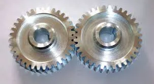
FIG: SPUR GEAR
PROCEDURE:
Case :1 By Using Cast Iron(ductile) as a material, to carry out a static structural analysis and to find out Equivalent stress, Total deformation and Stress intensity. as well as to Find the location for possible fracture
1. Open the ANSYS Workbench software. Under the Analysis system select the Static structural and wait for few seconds to pop up the window, which contains Engineering data, Geometry, Model, setup, Solution and Results.
2. Rename the static structural as spur gear with cast iron.
3. Add the Cast iron material to the library and Update the cast iron material to the System, under the Engineering data.
4. Under geometry import the spur gear model.
5. Update the model by right click and edit the Model for meshing.
6. Wait for few seconds and ANSYS Mechanical will open as shown below. Under geometry rename the gears as right gear and left gear.
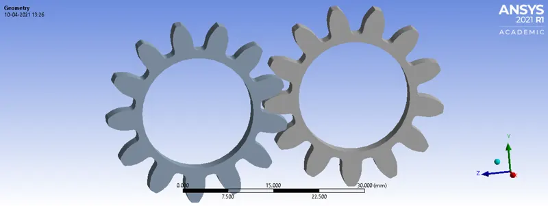
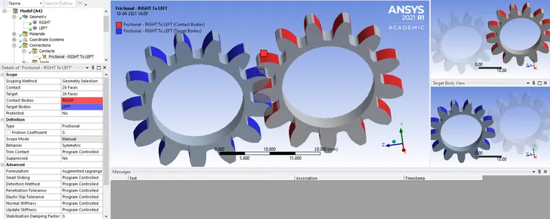
7. Define the contacts in between the tooth of the spur gears. we can define the contact for whole model, but the time taken for simulation will be high. so the contact is given in between the tooth where it is neccesary.
Change type to frictional, behavior to symmetric and formulation to augmented lagrange. Agmented lagrange will aviod the penentration of gears as well as scattering.
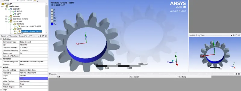
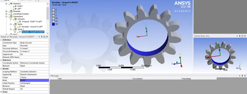
8. Insert a revolute joints for the gear in order to revolute about their axes. So click on connections go to insert and select joint. select body to ground option, type as revolute and select the inner face of the gear for reference. Follow the same method for another gear.
9. In ANSYS automatic mesh will be performed with Default mesh size and change the mesh size as 1mm.
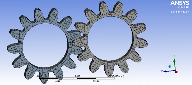
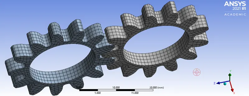
Be aware of ANSYS Student Edition and don't go beyond the size limit.
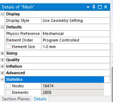
10. As it is a solid structure we have to change the 2D Element to 3D Element. So click on mesh and select the insert option. Under insert option select the method and slect the gemetry as well as under the method, select the tetrahedrons.
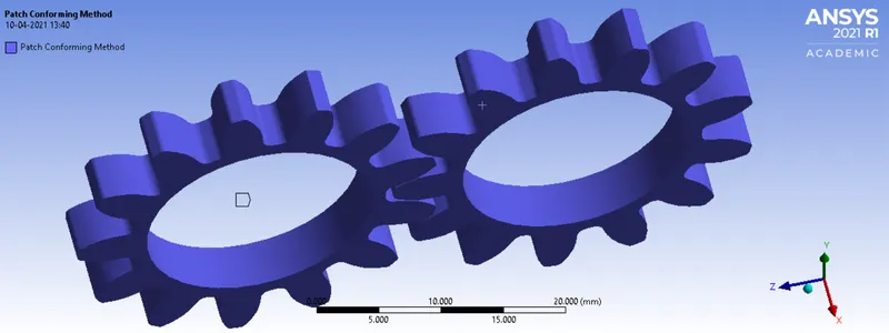
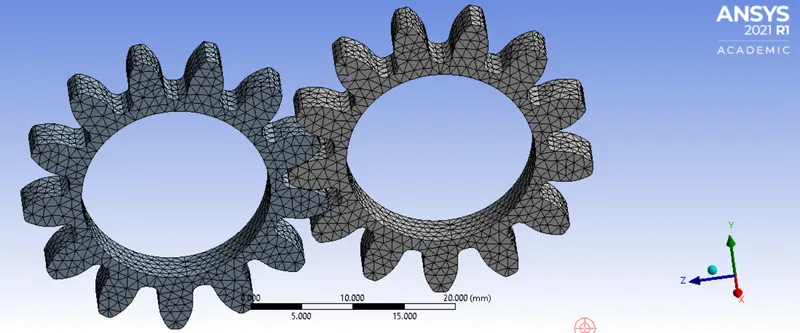
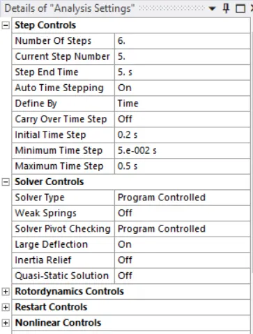
11. Analysis settings Change no. of steps as 6, step end time as 5s, auto time steeping on, define by time, carry over time step as off, intial time step as 0.2s, minimum time step as 5.e-002s, maximum time step as 0.5s.
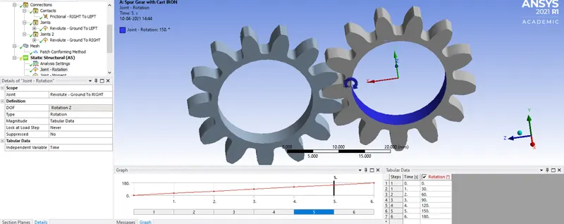
12. Now define the joint load for both the gears. so click on the static structural and select joint load, change the type as rotation for one gear and assign the rotational value in the table from 0, 30, 60, 90, 120, 150, 180. Then similarly insert the joint load and change the type to moment for rest of gear and assign the moment as 10Nm.
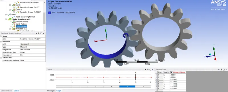
13. Now request for the outputs such as equivalent stress, equivalent elastic strain, total deformation and stress intensity.
The stress intensity factor is a concept in Fracture Mechanics that is used to measure the stress concentration at a crack tip. In safety design, It is compared to a critical value and evaluate whether a component or structure is prone to fracture.
14. SOLVE the solution and we can see the simulation run under soluion information.
The output requests are
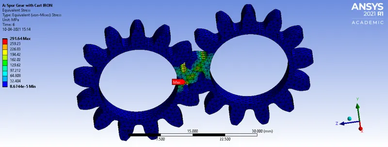
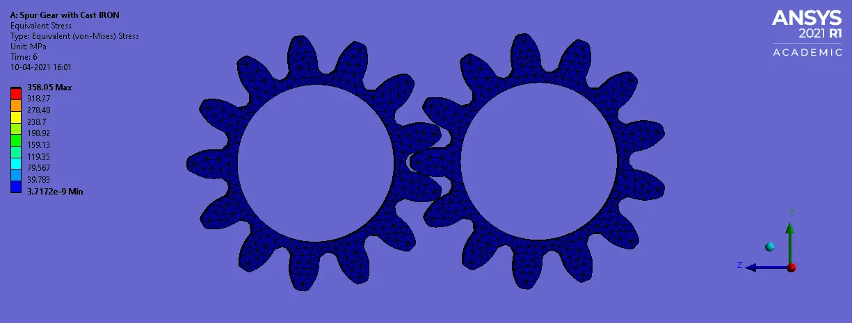
FIG: Equivalent (von-mises) stress
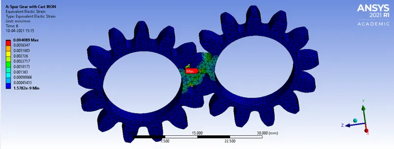
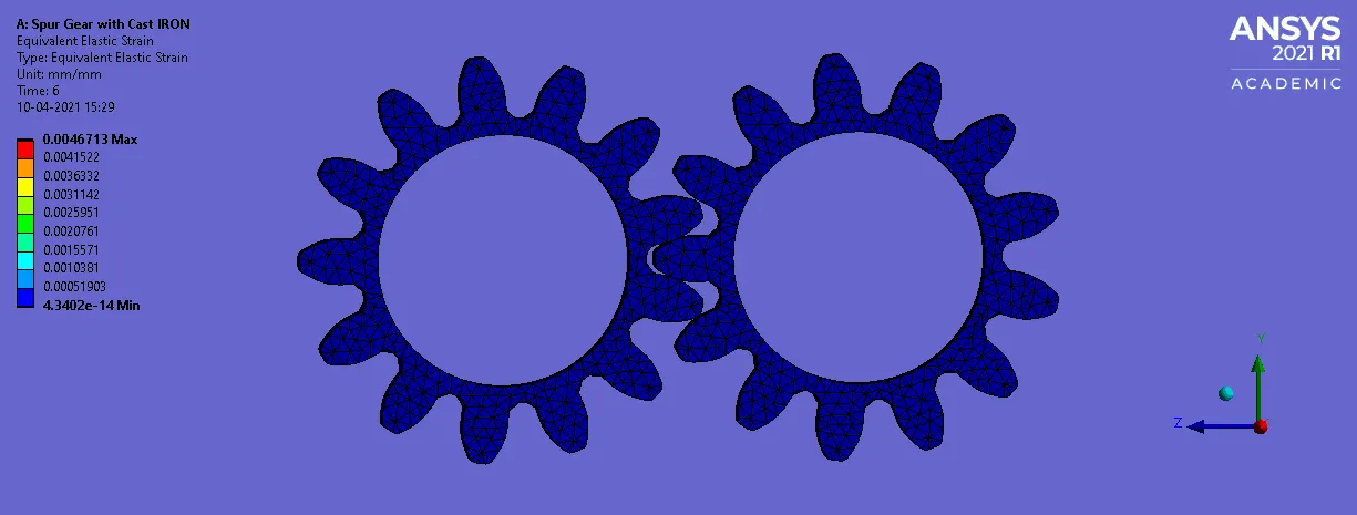
FIG: Equivalent elastic strain
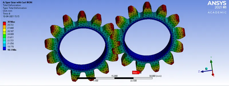
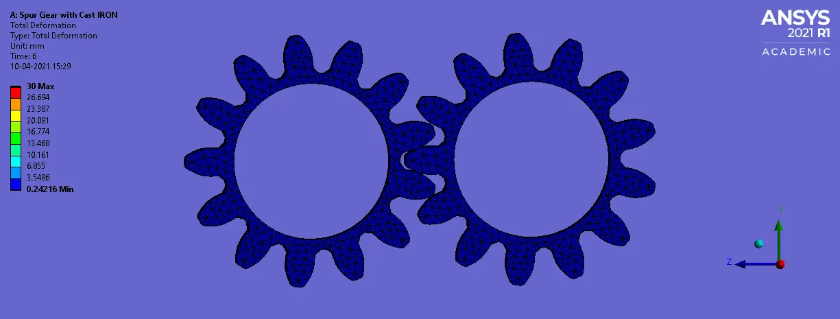
FIG: Total deformation
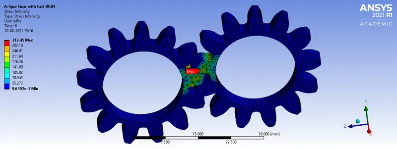
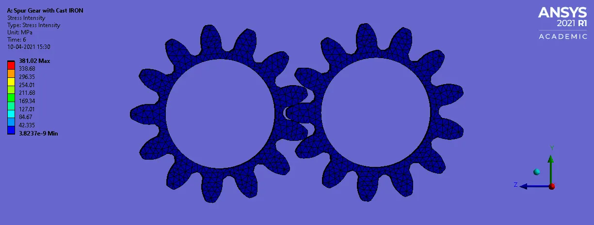
Fig: Stress Intensity
Case :2 By Using Cast Steel as a material, to carry out a static structural analysis and to find out Equivalent stress, Total deformation and Stress intensity. as well as to Find the location for possible fracture
1. Open the ANSYS Workbench software. Under the Analysis system select the Static structural and wait for few seconds to pop up the window, which contains Engineering data, Geometry, Model, setup, Solution and Results.
2. Rename the static structural as spur gear with cast Steel.
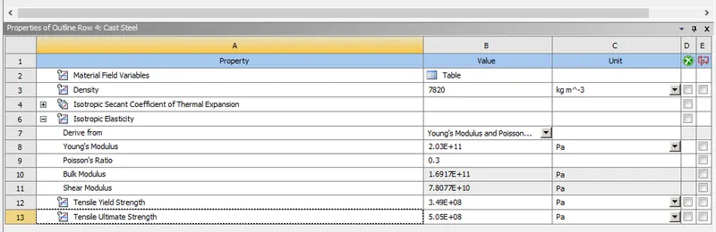
3. The cast steel material will not available in the library so create the material card and add the Cast steel material to the library and Update the cast iron material to the System, under the Engineering data.
4. Under geometry import the spur gear model.
5. Update the model by right click and edit the Model for meshing.
6. Wait for few seconds and ANSYS Mechanical will open as shown below. Under geometry rename the gears as right gear and left gear.
7. Define the contacts in between the tooth of the spur gears. we can define the contact for whole model, but the time taken for simulation will be high. so the contact is given in between the tooth where it is neccesary.
Change type to frictional, behavior to symmetric and formulation to augmented lagrange. Agmented lagrange will aviod the penentration of gears as well as scattering.
8. Insert a revolute joints for the gear in order to revolute about their axes. So click on connections go to insert and select joint. select body to ground option, type as revolute and select the inner face of the gear for reference. Follow the same method for another gear.
9. In ANSYS automatic mesh will be performed with Default mesh size and change the mesh size as 1mm.
Be aware of ANSYS Student Edition and don't go beyond the size limit.
10. As it is a solid structure we have to change the 2D Element to 3D Element. So click on mesh and select the insert option. Under insert option select the method and slect the gemetry as well as under the method, select the tetrahedrons.
11. Analysis settings Change no. of steps as 6, step end time as 5s, auto time steeping on, define by time, carry over time step as off, intial time step as 0.2s, minimum time step as 5.e-002s, maximum time step as 0.5s.
12. Now define the joint load for both the gears. so click on the static structural and select joint load, change the type as rotation for one gear and assign the rotational value in the table from 0, 30, 60, 90, 120, 150, 180. Then similarly insert the joint load and change the type to moment for rest of gear and assign the moment as 10Nm.
13. Now request for the outputs such as equivalent stress, equivalent elastic strain, total deformation and stress intensity.
The stress intensity factor is a concept in Fracture Mechanics that is used to measure the stress concentration at a crack tip. In safety design, It is compared to a critical value and evaluate whether a component or structure is prone to fracture.
14. SOLVE the solution and we can see the simulation run under soluion information.
The output requests are
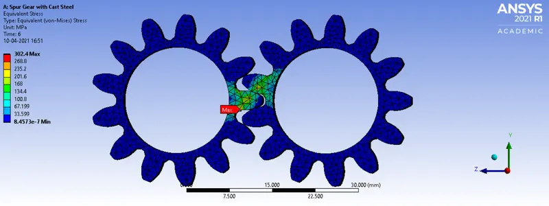
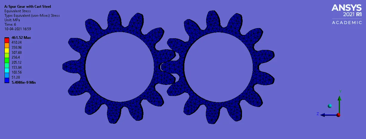
FIG: Equivalent (von-mises) stress
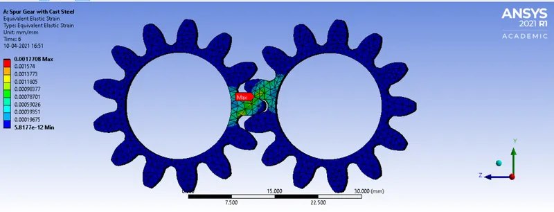
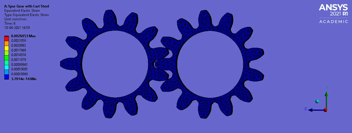
FIG: Equivalent elastic strain
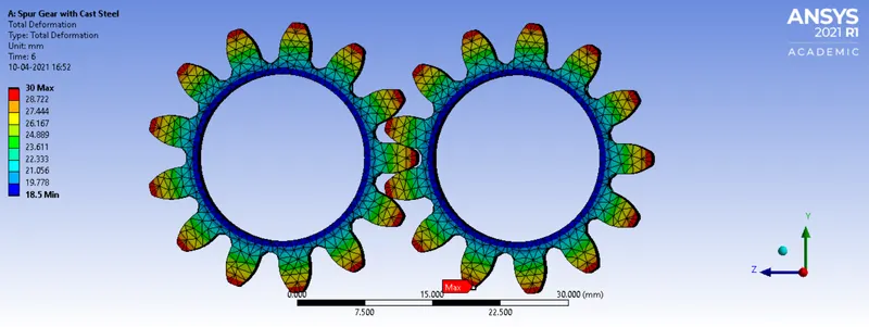
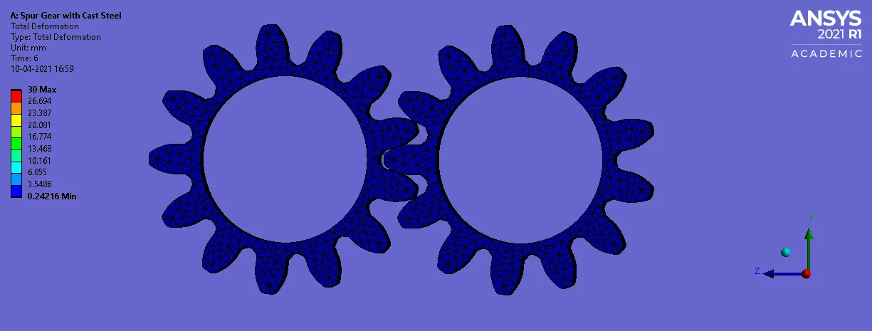
FIG: Total deformation
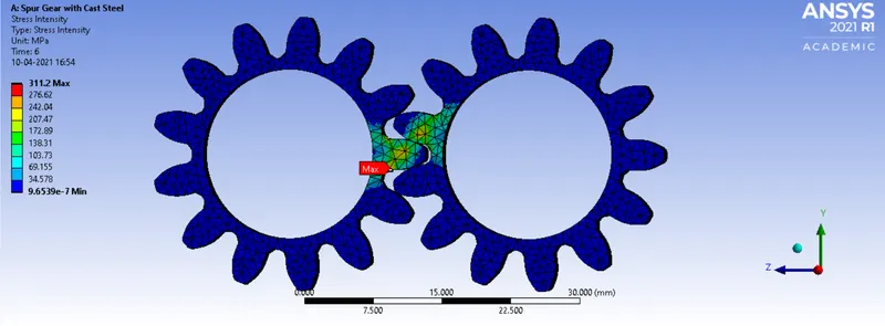
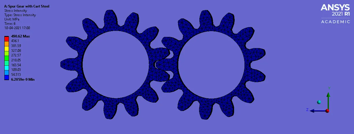
Fig: Stress Intensity
Case :3 By Using Cast Bronze as a material, to carry out a static structural analysis and to find out Equivalent stress, Total deformation and Stress intensity. as well as to Find the location for possible fracture
1. Open the ANSYS Workbench software. Under the Analysis system select the Static structural and wait for few seconds to pop up the window, which contains Engineering data, Geometry, Model, setup, Solution and Results.
2. Rename the static structural as spur gear with cast bronze.
3. The Cast Bronze material will not available in the library so create the material card and add the Cast steel material to the library and Update the cast iron material to the System, under the Engineering data.
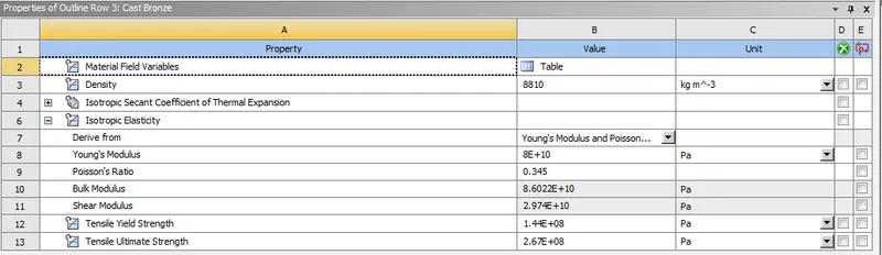
4. Under geometry import the spur gear model.
5. Update the model by right click and edit the Model for meshing.
6. Wait for few seconds and ANSYS Mechanical will open as shown below. Under geometry rename the gears as right gear and left gear.
7. Define the contacts in between the tooth of the spur gears. we can define the contact for whole model, but the time taken for simulation will be high. so the contact is given in between the tooth where it is neccesary.
Change type to frictional, behavior to symmetric and formulation to augmented lagrange. Agmented lagrange will aviod the penentration of gears as well as scattering.
8. Insert a revolute joints for the gear in order to revolute about their axes. So click on connections go to insert and select joint. select body to ground option, type as revolute and select the inner face of the gear for reference. Follow the same method for another gear.
9. In ANSYS automatic mesh will be performed with Default mesh size and change the mesh size as 1mm.
Be aware of ANSYS Student Edition and don't go beyond the size limit.
10. As it is a solid structure we have to change the 2D Element to 3D Element. So click on mesh and select the insert option. Under insert option select the method and slect the gemetry as well as under the method, select the tetrahedrons.
11. Analysis settings Change no. of steps as 6, step end time as 5s, auto time steeping on, define by time, carry over time step as off, intial time step as 0.2s, minimum time step as 5.e-002s, maximum time step as 0.5s.
12. Now define the joint load for both the gears. so click on the static structural and select joint load, change the type as rotation for one gear and assign the rotational value in the table from 0, 30, 60, 90, 120, 150, 180. Then similarly insert the joint load and change the type to moment for rest of gear and assign the moment as 10Nm.
13. Now request for the outputs such as equivalent stress, equivalent elastic strain, total deformation and stress intensity.
The stress intensity factor is a concept in Fracture Mechanics that is used to measure the stress concentration at a crack tip. In safety design, It is compared to a critical value and evaluate whether a component or structure is prone to fracture.
14. SOLVE the solution and we can see the simulation run under soluion information.
The output requests are
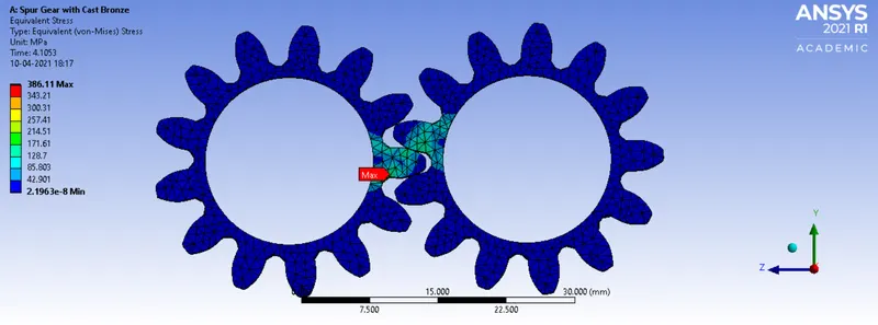
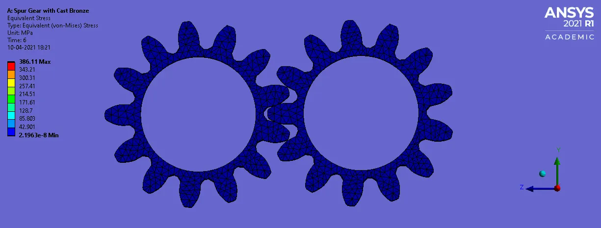
FIG: Equivalent (von-mises) stress
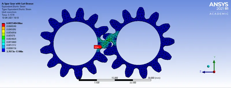
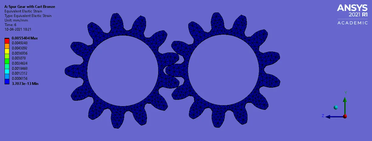
FIG: Equivalent elastic strain
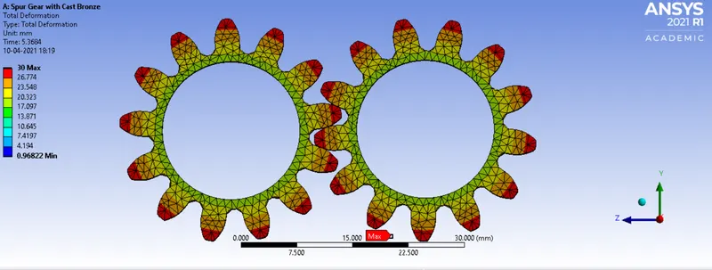
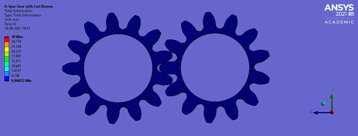
FIG: Total deformation
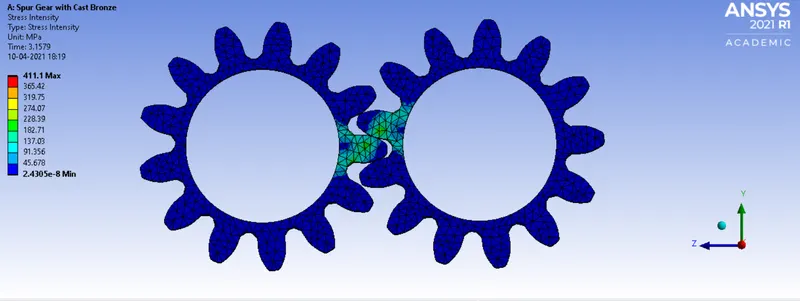
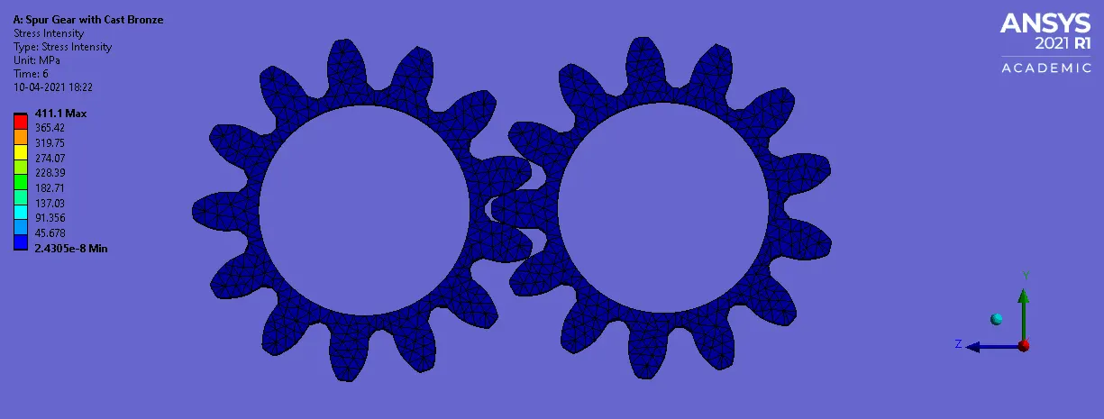
Fig: Stress Intensity
RESULTS
COMPARISM OF ALL THREE CASES RESULT: FOR MAXIMUM VALUE
| CASES | MATERIAL |
EQUIVALENT STRESS (MPa) |
EQUIVALENT ELASTIC STRAIN |
TOTAL DEFORMATION (mm) |
STRESS INTENSITY (MPa) |
| 1. | Cast Iron | 358.05 | 0.0046713 | 30 | 381.02 |
| 2. | Cast steel | 461.52 | 0.0026953 | 30 | 490.62 |
| 3. | Cast Bronze | 386.11 | 0.0055404 | 30 | 411.1 |
The stress intensity factor,  , is used in fracture mechanics to predict the stress state ("stress intensity") near the tip of a crack or notch caused by a remote load or residual stresses. It is a theoretical construct usually applied to a homogeneous, linear elastic material and is useful for providing a failure criterion for brittle materials, and is a critical technique in the discipline of damage tolerance. The concept can also be applied to materials that exhibit small-scale yielding at a crack tip.
CONCLUSION AND DISSCUSSION:
The stress intensity factor is used to know whether the material will fracture or not, if the stress intensity factor exceeds the fracture toughness value, then the material will fracture. The cast iron will have less equivalent stress when compared with cast steel and cast bronze. From our point of view we select a material that that will have less stress. As well as the stress intensity of cast iron will be less when compared with the cast steel and cast bronze. so Based on the comparism we will recommend the cast iron material. And the Total deformation for all cases will remain same.