Week 4-1D Element Creation Challenge
Week 4-1D Element Creation Challenge
OBJECTIVE: The Objective of this challenge is to create the mesh on the given component with the Size of 5 Units. To Create 1D elements on the following component with given cross-section and DOF.
a. Rod element:- Translational DOF should be Constrained with RBE2 link
Cross-Section: BOX- Dimension a= 12 mm
dimension b=10 mm
Thickness t= 0.75 mm
b. Beam element:- All DOF should be constrained with RBE3 link
Cross-Section: I Section- Dimension a= 8 mm
Dimension b= 10 mm
Dimension c= 8.5 mm
Thickness t1= 0.75 mm
Thickness t2= .6 mm
Thickness t3= .6 mm
c. Bar element:- Constrain only x and y DOFs With RBE3 link
Cross-section: X section- Dimension DIM1= 5 mm
Thickness DIM2= 1.2 mm
Dimension DIM3= 10 mm
Thickness DIM4= 1.2mm
d. & e. To Apply the mass of magnitude 10 with the RBE2 link
f. To Join the two components with Spring elements
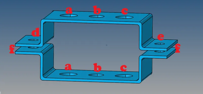
Fig:1 Parallel Bracket
Software Used: Hyperworks desktop 2021
Procedure:
1.Open Hyperworks desktop 2021 and set the user profile as Optistruct.
2. Select import solver deck and choose import geometry, select the location where we had saved the model and import it.
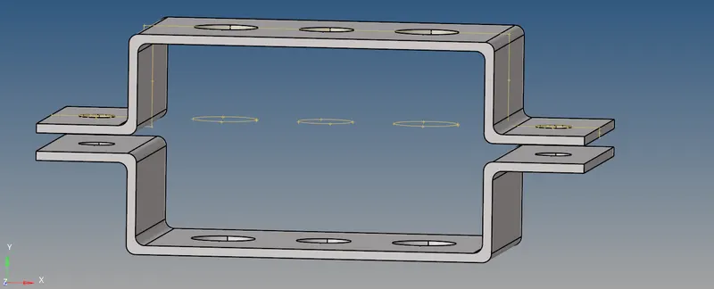
Fig:2 Parallel Bracket
3. Choose the delete option and select solids-displayed and delete entity. This helps in creating the midsurface.
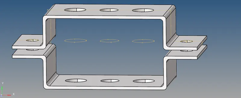
Fig:3 Selecting solids of Parallel Bracket
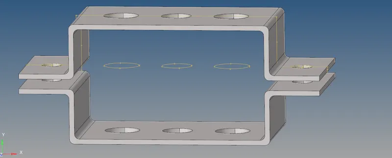
Fig:4 Solids Deleted
4. Create a Midsurface by selecting the geometry panel and click on Midsurface option, select the surfaces to create misurface and choose extraction option as offset, which will trace the surface exactly when compare with others.
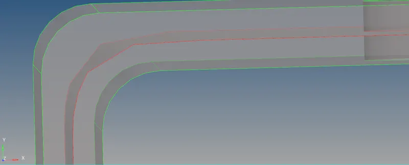
Fig:5 Auto extraction - offset+planes+sweeps
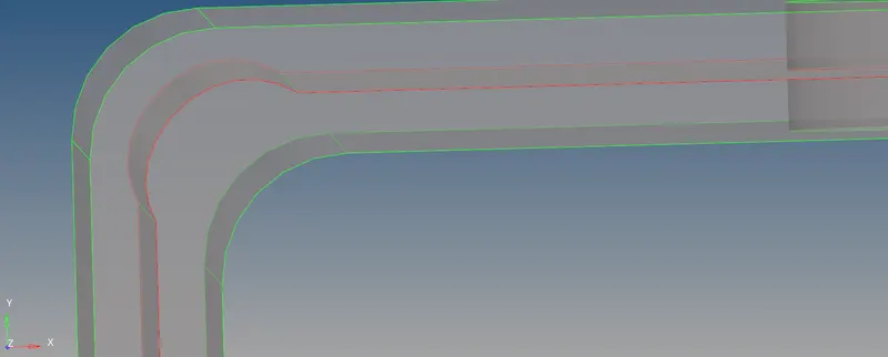
Fig:6 Auto extraction - offset+planes
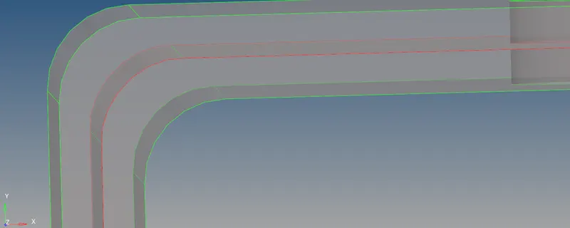
Fig:7 Auto extraction - offset
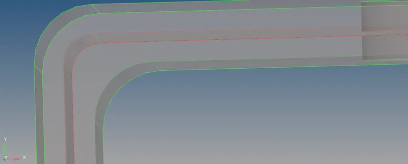
Fig:8 Auto extraction - Skin offset
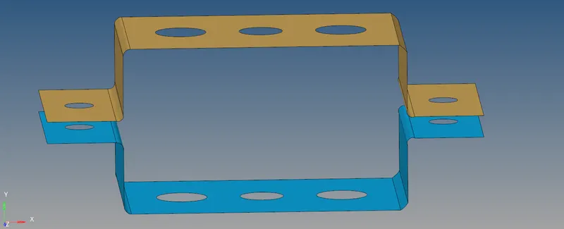
Fig:9 Mid Surface extraction
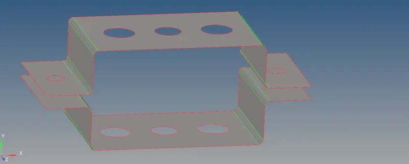
Fig:9.1 Mid Surface extraction by topo
5. Now create a washer split of 5mm to all the holes as shown below.
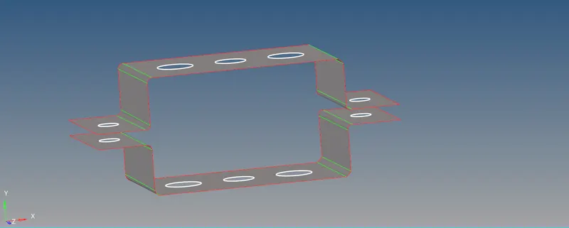
Fig:10 Washer split of 5mm
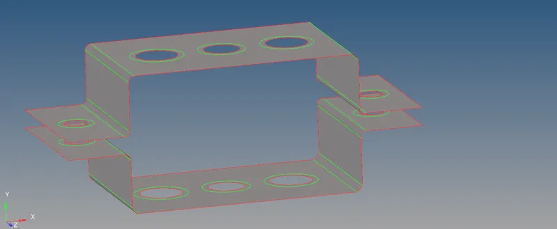
Fig:10.1 Washer split of 5mm
6. Go to 2D, auto mesh select the surfaces to be mesh and choose the element size as 5mm and mesh type as mixed.
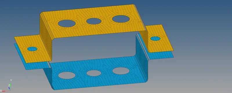
Fig:11 Meshing
7. Create a material card as shown below. And assign to bracket_1 and bracket_2
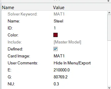
Fig:12 Material card
8. Create the property card as shown below and assign the material thickness as 2.0mm and 2.5mm. Card iage as Pshell. Assign it to the brackets.
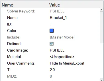
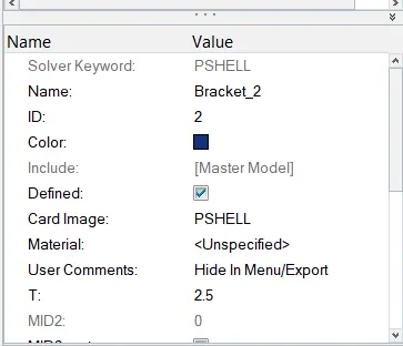
Fig:13 Property card
9. a. Rod element:-Translational DOF should be Constrained with RBE2 link
Cross-Section: BOX- Dimension a= 12 mm
dimension b=10 mm
Thickness t= 0.75 mm
Go to 1D, Rigids (Element type as RBE2) and select the nodes as shown below and type of nodes as multiple, calulate node.
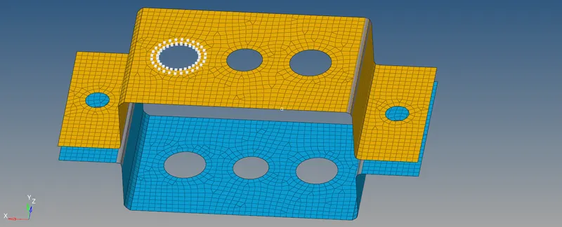
Fig:14 Selecting nodes for creating RBE2
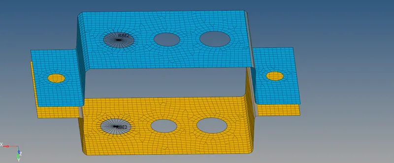
Fig:15 RBE2 Link for Rod element.

Fig:14 Translational DOF Constrained
Create the Cross-Section: BOX- Dimension a= 12 mm
dimension b=10 mm
Thickness t= 0.75 mm
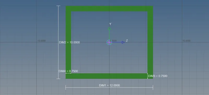
Fig:16 Cross-Section: BOX
10. Create the property card as shown below and change the card image as PROD, Beam section as Box section.
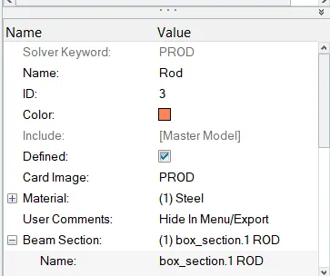
Fig:17 Property card
11. Select 1D Panel and Click on the rod option select the nodes as shown below and assign respected property and element type to the rod.
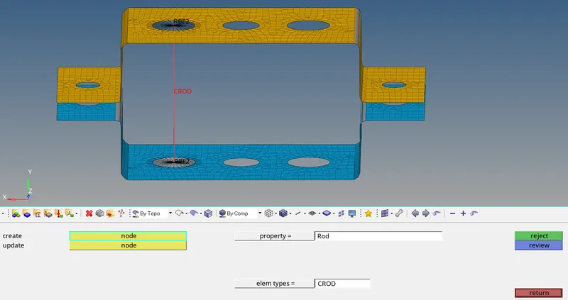
Fig:18 Rod creation
12. b. Beam element:- All DOF should be constrained with RBE3 link
Cross-Section: I Section- Dimension a= 8 mm
Dimension b= 10 mm
Dimension c= 8.5 mm
Thickness t1= 0.75 mm
Thickness t2= .6 mm
Thickness t3= .6 mm
Go to 1D, Rigids (Element type as RBE3) and select the nodes as shown below and type of nodes as multiple, calulate node.
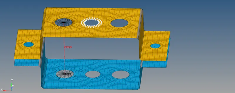
Fig:19 Selecting nodes for creating RBE3
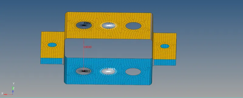
Fig:20 RBE3 Link for Beam element.

Fig:21 All DOF constrained
Cross-Section: I Section- Dimension a= 8 mm
Dimension b= 10 mm
Dimension c= 8.5 mm
Thickness t1= 0.75 mm
Thickness t2= .6 mm
Thickness t3= .6 mm
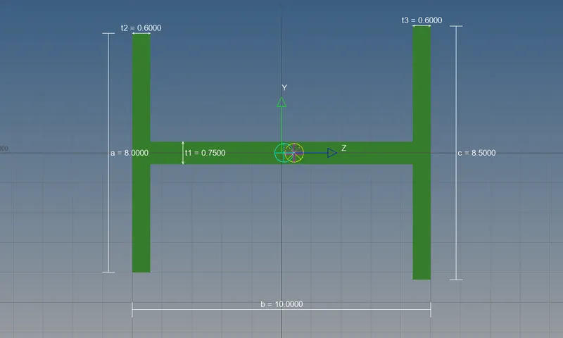
Fig:22 Cross-Section: I Section
13. Create the property card as shown below and change the card image as PBEAM, Beam section as I section.
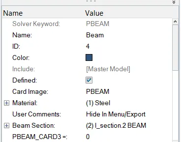
Fig:23 Property card
14. Select 1D Panel and Click on the Bar option, select the nodes as shown below and assign respected property and element type to the beam.
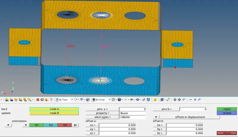
Fig:24 Beam creation
15. c. Bar element:- Constrain only x and y DOFs With RBE3 link
Cross-section: X section- Dimension DIM1= 5 mm
Thickness DIM2= 1.2 mm
Dimension DIM3= 10 mm
Thickness DIM4= 1.2mm
Go to 1D, Rigids (Element type as RBE3) and select the nodes as shown below and type of nodes as multiple, calulate node.
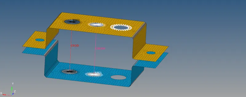
Fig:25 Selecting nodes for creating RBE3
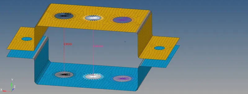
Fig:26 RBE3 Link for Bar element.

Fig:27 Constrain only x and y DOFs With RBE3 link
Cross-section: X section- Dimension DIM1= 5 mm
Thickness DIM2= 1.2 mm
Dimension DIM3= 10 mm
Thickness DIM4= 1.2mm
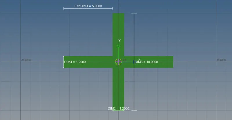
Fig:28 Cross-Section: X Section
16. Create the property card as shown below and change the card image as PBAR, Beam section as CROSS section.
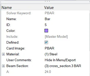
Fig:29 Property card
17. Select 1D Panel and Click on the Bar option, select the nodes as shown below and assign respected property and element type to the Bar.
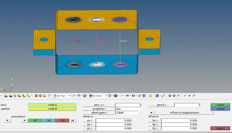
Fig:30 Bar creation
18. d. & e. Apply the mass of magnitude 10 with the RBE2 link
First create the RBE2 Link by following the same procedure as mentioned above make all dof constraint.
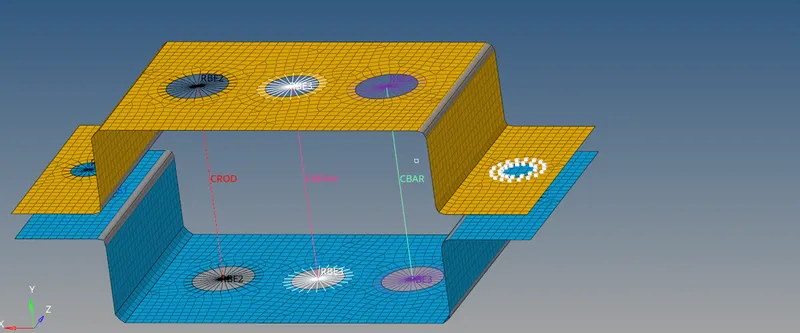
Fig:31 Selecting nodes for creating RBE2
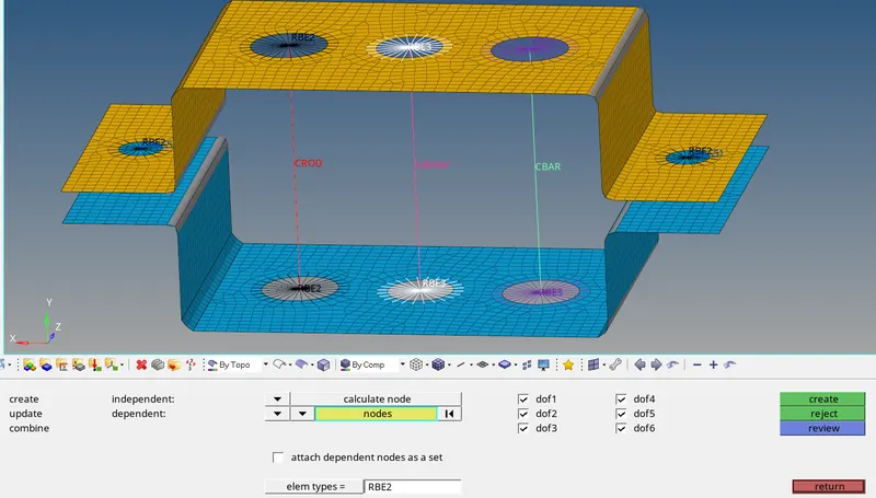
Fig: 32 RBE2 Link for adding Mass
Now Under 1D Panel select the Mass and select the respective nodes to add the mass with a magnitude of 10.
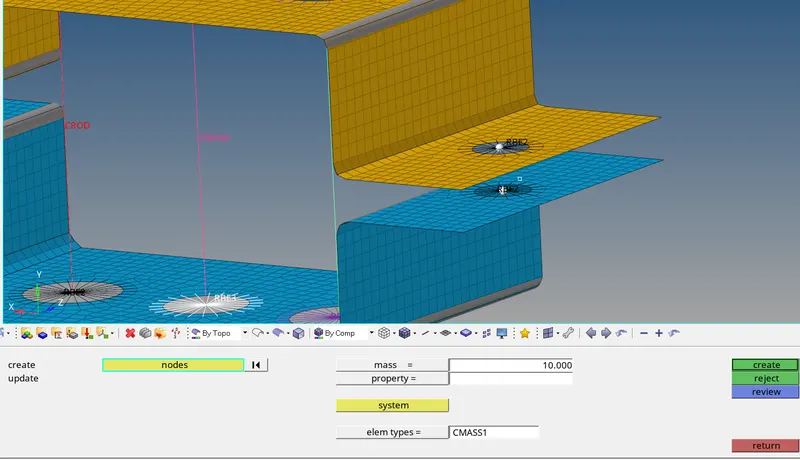
Fig:33 Adding Mass
19. f. Join the two components with Spring elements
Now Under 1D Panel select the Springs and select the respective nodes as shown below to add the Springs.
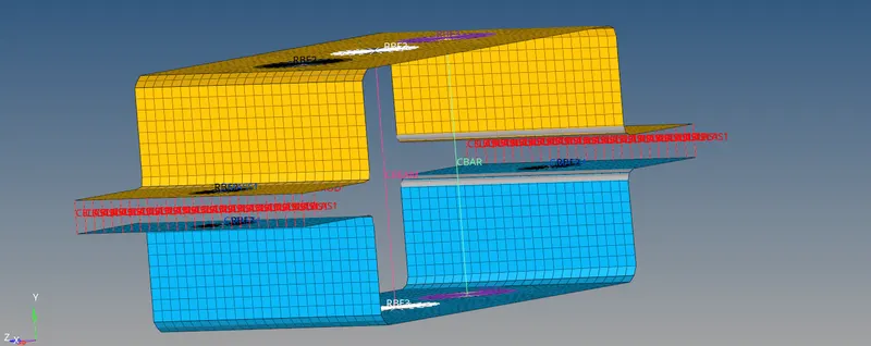
Fig: 34 Adding Springs
RESULT AND FINAL IMAGES:
The mesh is generated with a element size of 5mm, the 1D Elements, Property, rigids, masses, springs and cross sections are also created at the respected places.
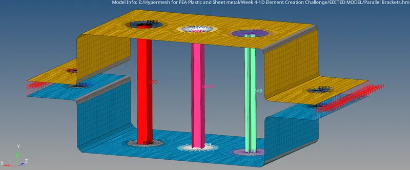
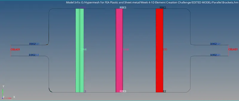
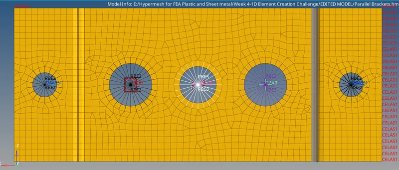
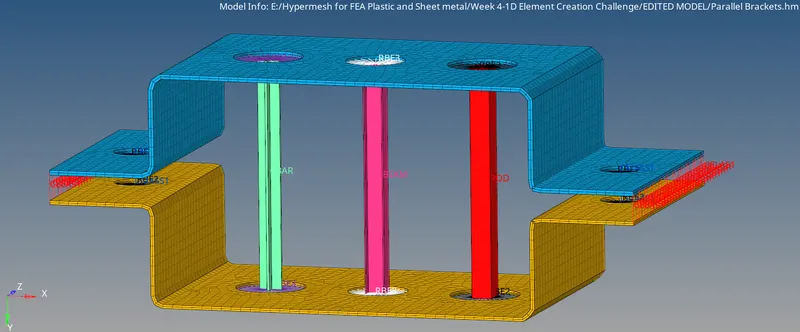
FIG: FINAL IMAGES: