Week 11 Car Crash simulation
Car Crash simulation
OBJECTIVE: The main objective of this challenge is to perform explicit dynamic analysis of a car body and to perform a parametric study using 3 different values of thickness such as 0.3mm, 0.5mm and 0.6mm for the car body. To apply the same conditions as mentioned in the video and to analyse the total deformation and Equivalent stresses acting on the model.
SOFTWARE USED: ANSYS Workbench 2021 R1 and ANSYS Mechanical for Analysis.
INTRODUCTION:
A crash simulation is a virtual recreation of a destructive crash test of a car or a highway guard rail system using a computer simulation in order to examine the level of safety of the car and its occupants. Crash simulations are used by automakers during computer-aided engineering(CAE) analysis for crashworthiness in the computer-aided design (CAD) process of modelling new cars. During a crash simulation, the kinetic energy, or energy of motion, that a vehicle has before the impact is transformed into deformation energy, mostly by plastic deformation (plasticity) of the car body material (Body in White), at the end of the impact.
Data obtained from a crash simulation indicate the capability of the car body or guard rail structure to protect the vehicle occupants during a collision (and also pedestrians hit by a car) against injury. Important results are the deformations (for example, steering wheel intrusions) of the occupant space (driver, passengers) and the decelerations (for example, head acceleration) felt by them, which must fall below threshold values fixed in legal car safety regulations. To model real crash tests, today's crash simulations include virtual models of crash test dummies and of passive safety devices (seat belts, airbags, shock absorbing dash boards, etc.). Guide rail tests evaluate vehicle deceleration and rollover potential, as well as penetration of the barrier by vehicles.
Fig.1: Car Crash
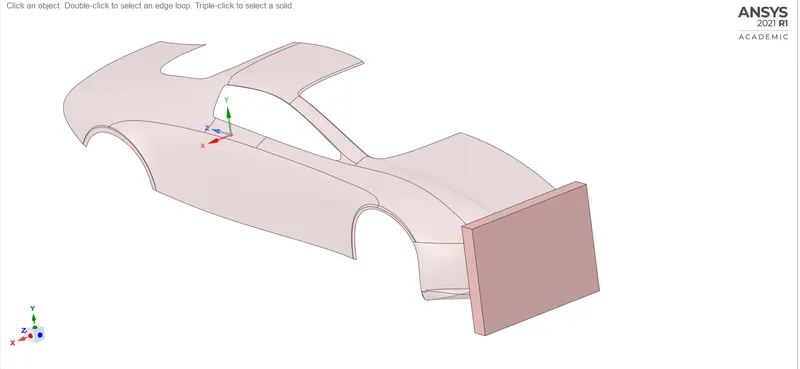
FIG.2: CAD MODEL
PROCEDURE:
1. Open the ANSYS Workbench software. Under the Analysis system select the Explicit Dynamics and wait for few seconds to pop up the window, which contains Engineering data, Geometry, Model, setup, Solution and Results.
2. Rename the Explicit Dynamics as Car Crash simulation.
3. Under geometry import the car crash simulation model.
4. Update the model by right click and edit the Model for Preprocessing.
5. Wait for few seconds and ANSYS Mechanical will open as shown below. Rename the model as Wall and Car body
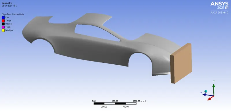
FIG.3: CAD model of a Car crash Test model.
SYMETRY: Insert a symetry to the wall and car. Insert the symetry region and select the face of the wall. Similarly again select the symetry region and select the edges of the car body as shown below.
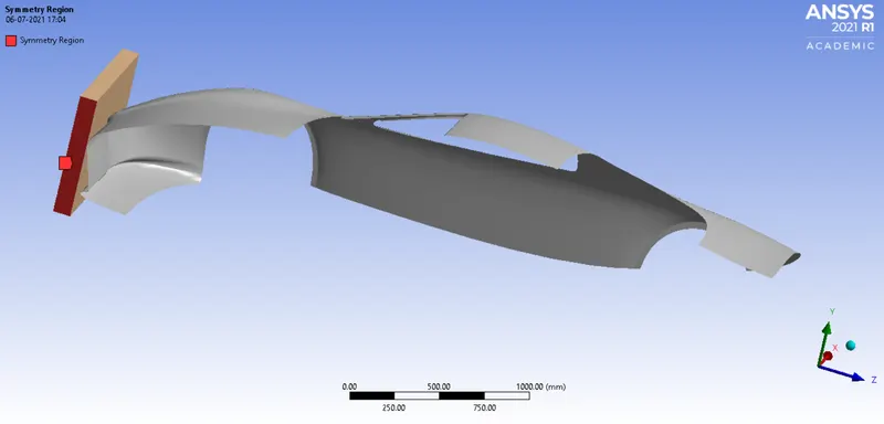
Fig.4: Selecting faces for symetry
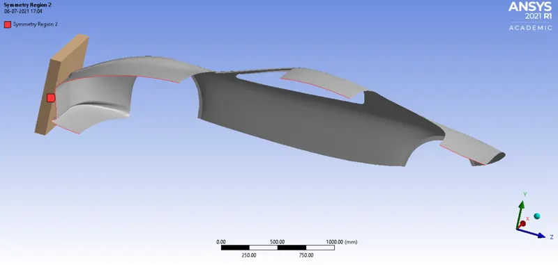
Fig.5: Selecting edges for symetry
6. Assign the material to the model. Right click on engineering data and under engineering data sources select explicit materials and assign Stainless steel (NL) to the car body, and a thickness of 0.3mm. Structural steel for wall as default.
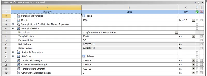
FIG 6: Material properties of a Structural Steel
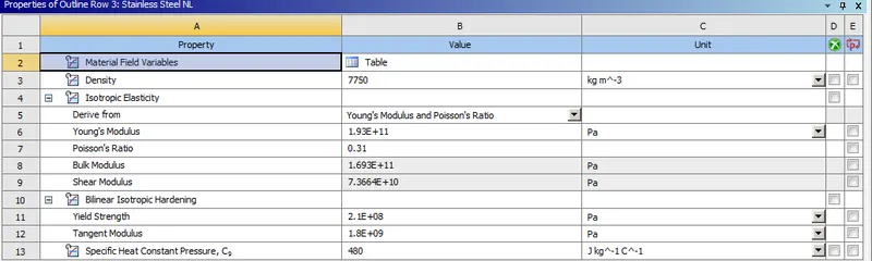
FIG 7: Material properties of a Stainless Steel
7. Connections Delete the default bonded contact.
8. In ANSYS automatic mesh will be performed with Default mesh size, so insert method and select the wall and choose method type as tetrahedrans and select the sizing option, select the face of car body as shown below, and assign an element size of 175mm, and also insert a method and select the carbody and choose method type as triangles.
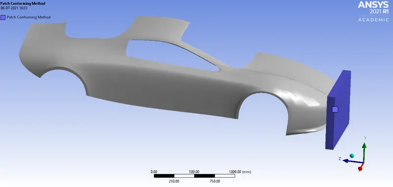
Fig.8: Method selection for tetrahedrans
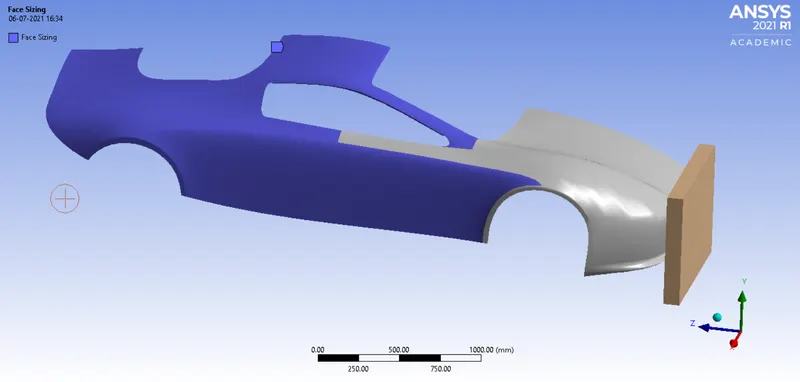
Fig.9: Selecting faces for Coarse mesh
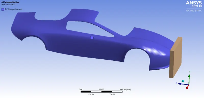
Fig.10: Method selection for triangles
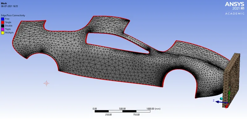
Fig.11: Meshing
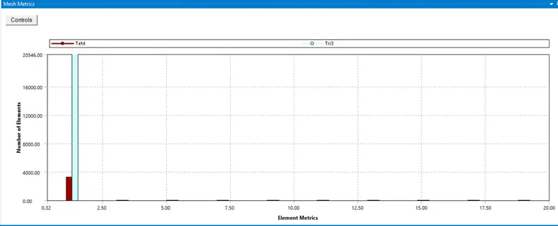
Fig.12: Mesh Quality
9. Fixed support: Insert a fixed support to the car body and select the face as shown below.
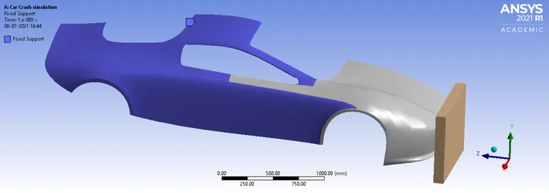
Fig.13: Fixed support
10. Displacement: Insert the Displacement and select the back side face of the wall as scope and a magnitude of 500mm in Z-direction.
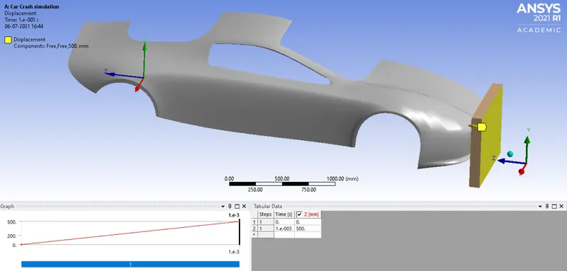
Fig.14: Displacement
11. Analysis settings: change the end time as 0.001s. And remaining settings as default.
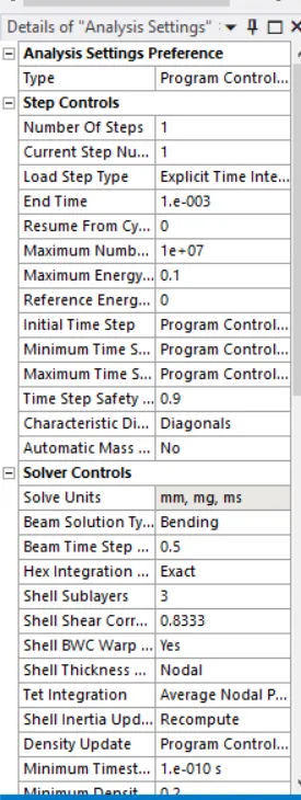
FIG 15: Analysis settings
12. Now request for the outputs such as equivalent stress, equivalent elastic strain, Total deformation and directional deformation Z-axis.
13. SOLVE the solution and we can see the simulation run under soluion information.
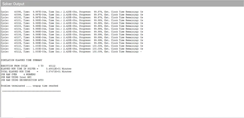
FIG.16: Solver output
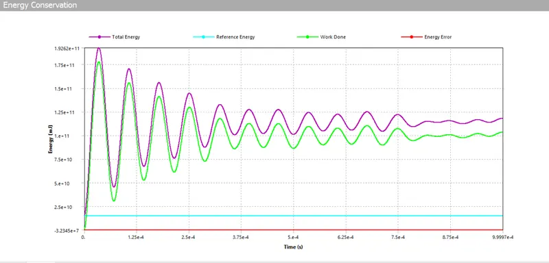
Fig.17 Energy Conservation
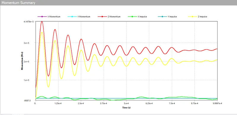
Fig.18 Momentum Summary
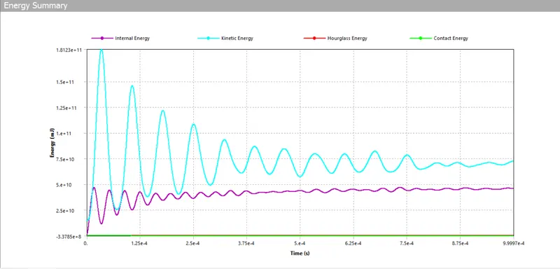
Fig.19: Energy Summary
Now parameter set is applied to the model.
We have to test the model with three types of thickness (i.e 0.3mm, 0.5mm and 0.6mm) so select the box as shown below in order to activate the parameter set.
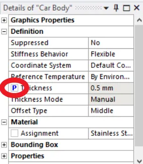
Fig.20: parameter set
Similarly request for the output parameters in order to view the output requests. then we can see the parameter set as shown below. Double click on it to view further details. Then give the thickness as 0.5mm and 0.6mm as the design points. Finally update all design points.
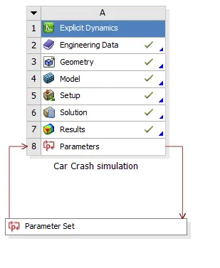
Fig.21: parameter set
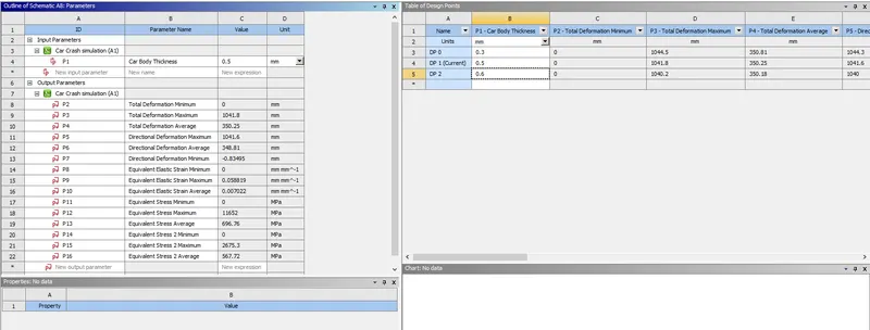
Fig.22: Table of design points
We can view the simulations by making the respective thickness as set to current.
SIMULATION RESULT:
For the car body thickness of 0.3mm
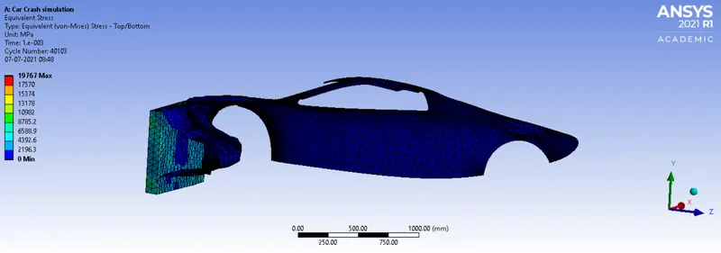
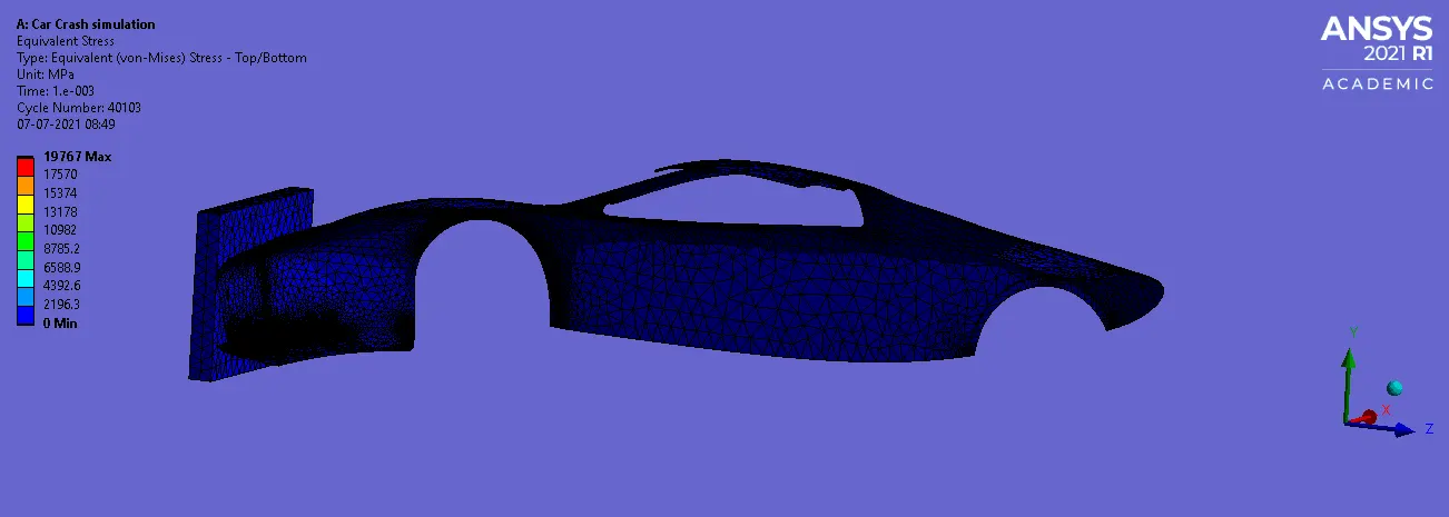
Fig 23: Equivalent Stress
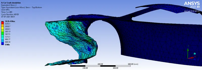
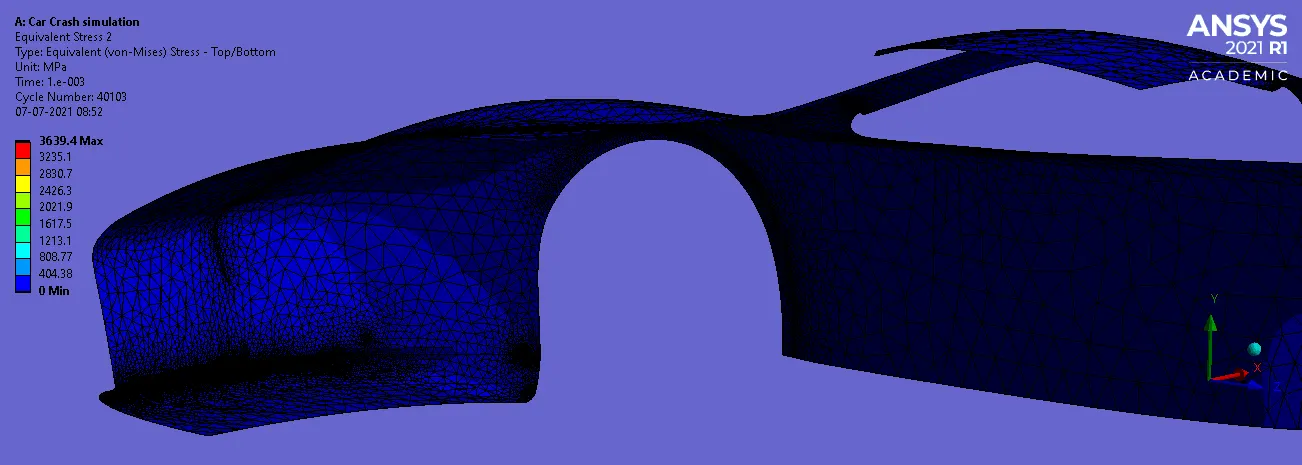
Fig 24: Equivalent Stress in the car body
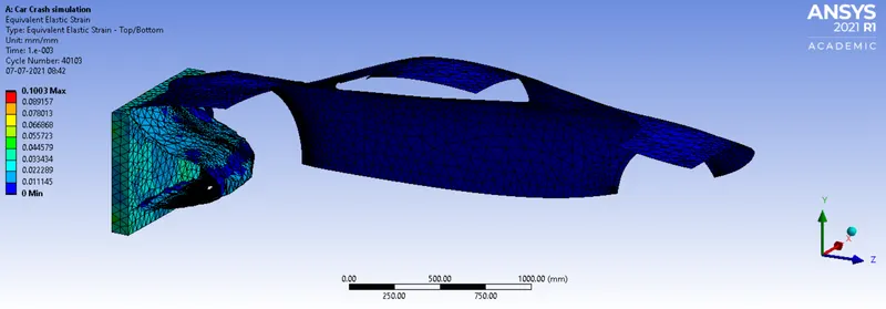
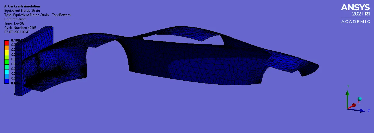
Fig 25: Equivalent Elastic Strain
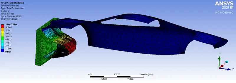
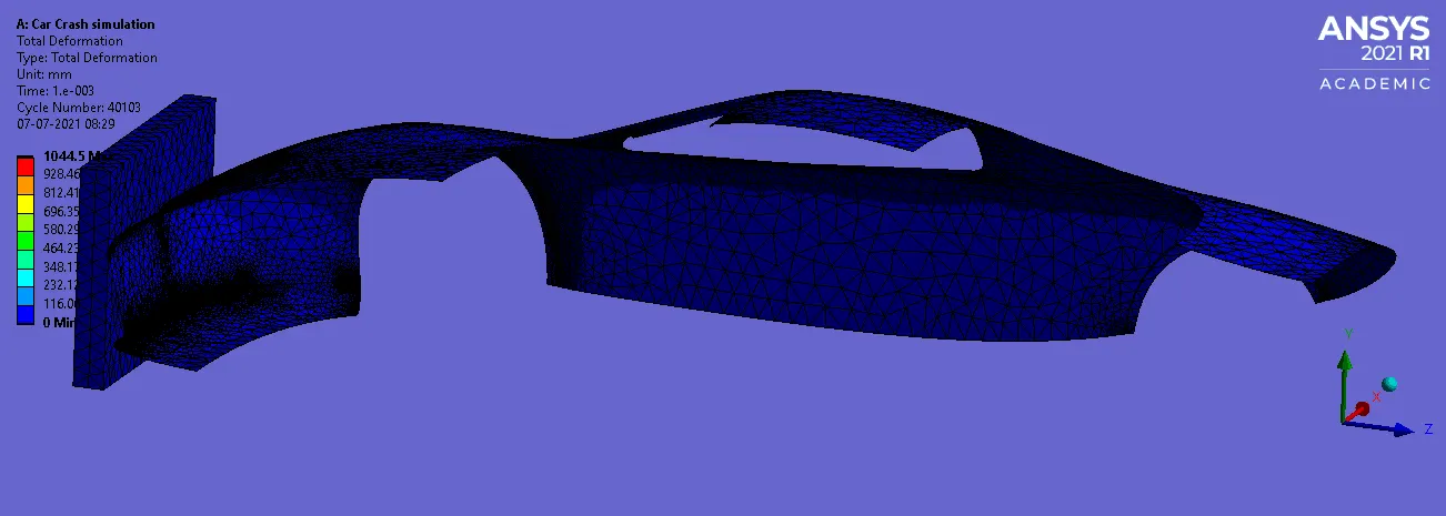
Fig 26: Total Deformation
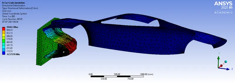
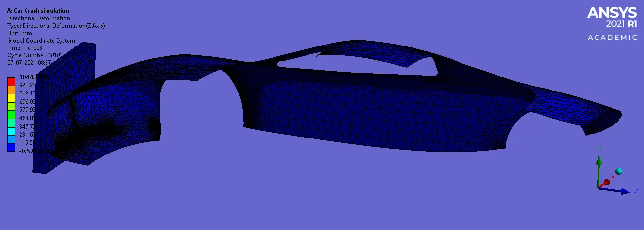
Fig 27: Directional Deformation about Z-Axis
For the car body thickness of 0.5mm
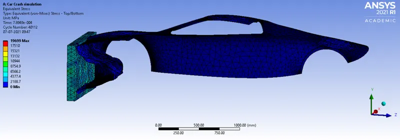
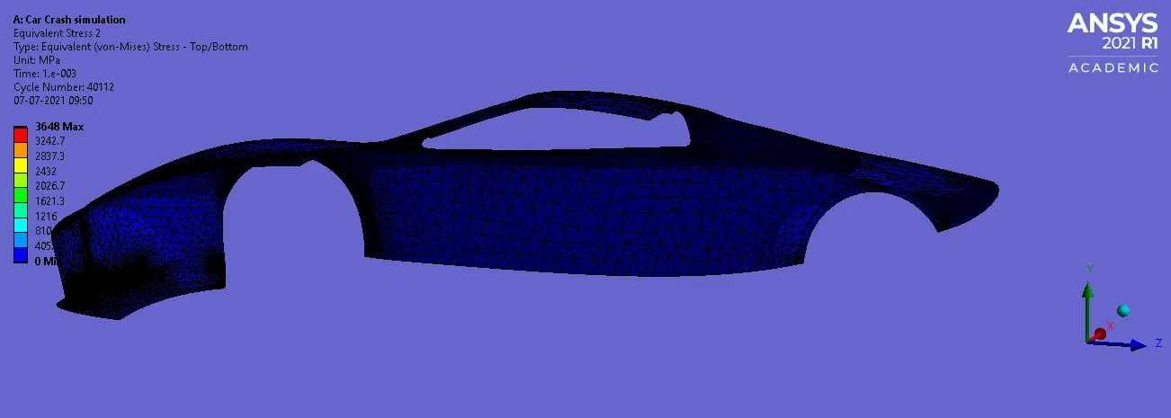
Fig 28: Equivalent Stress
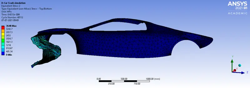
Fig 29: Equivalent Stress in the car body
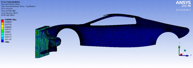
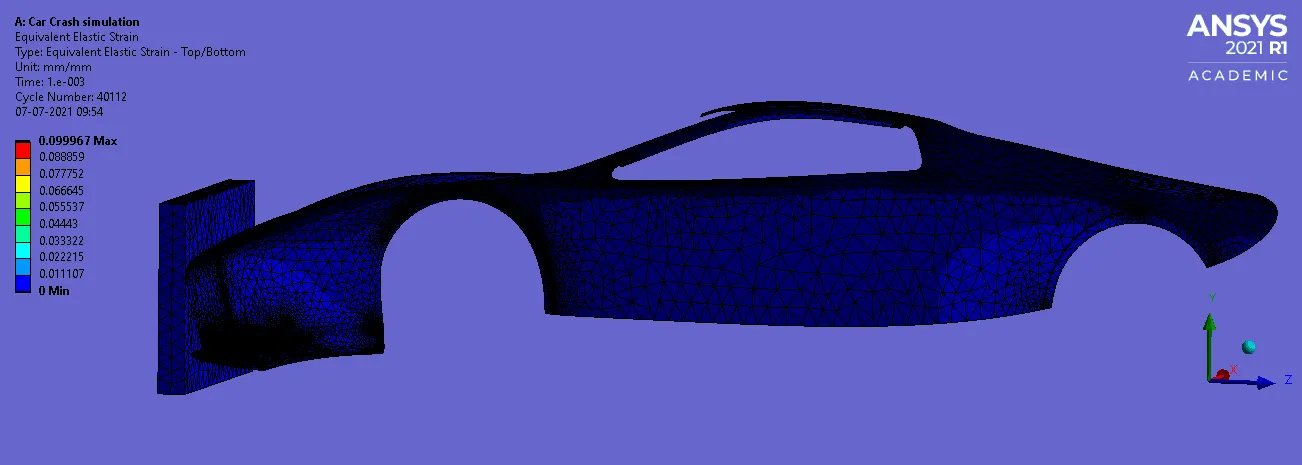
Fig 30: Equivalent Elastic Strain
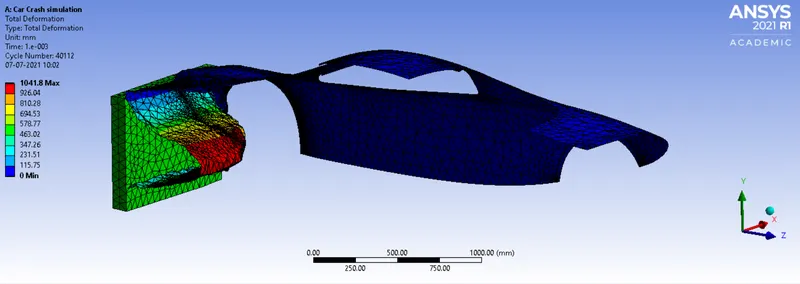
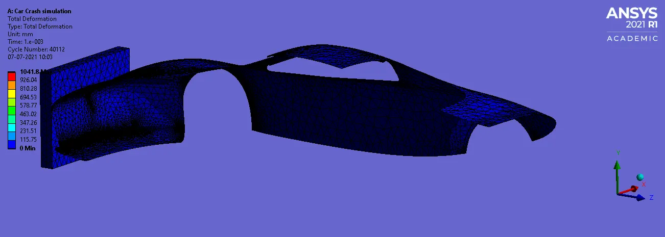
Fig 31: Total Deformation
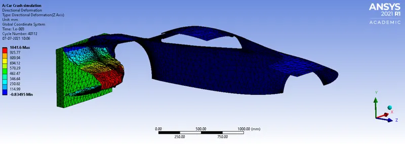
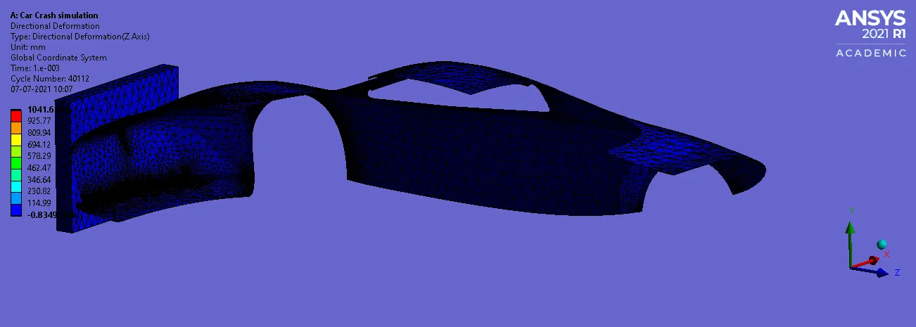
Fig 32: Directional Deformation about Z-Axis
For the car body thickness of 0.6mm
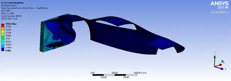
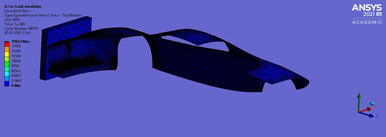
Fig 33: Equivalent Stress
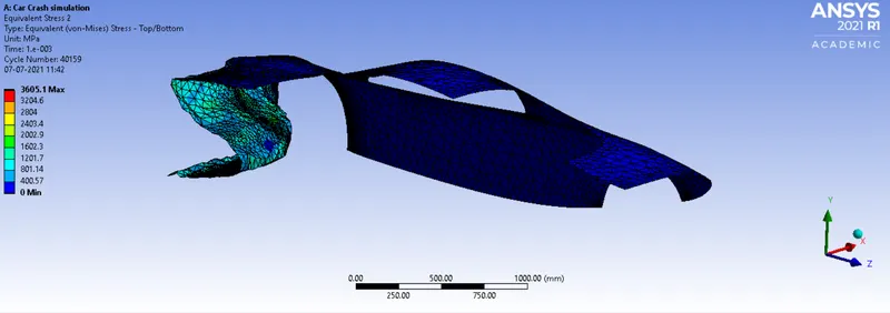
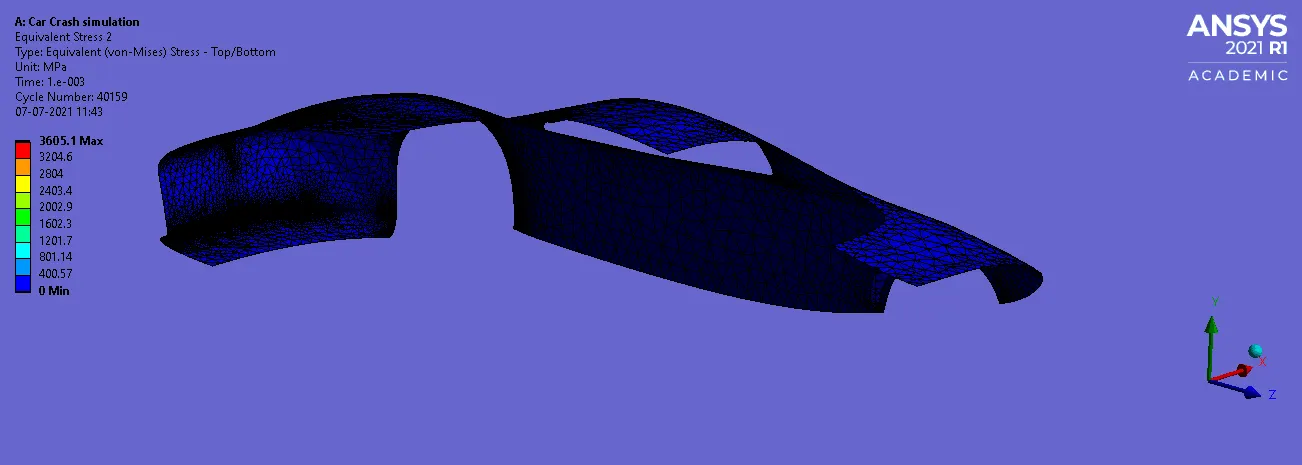
Fig 34: Equivalent Stress in the car body
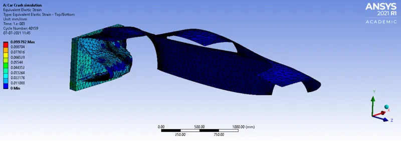
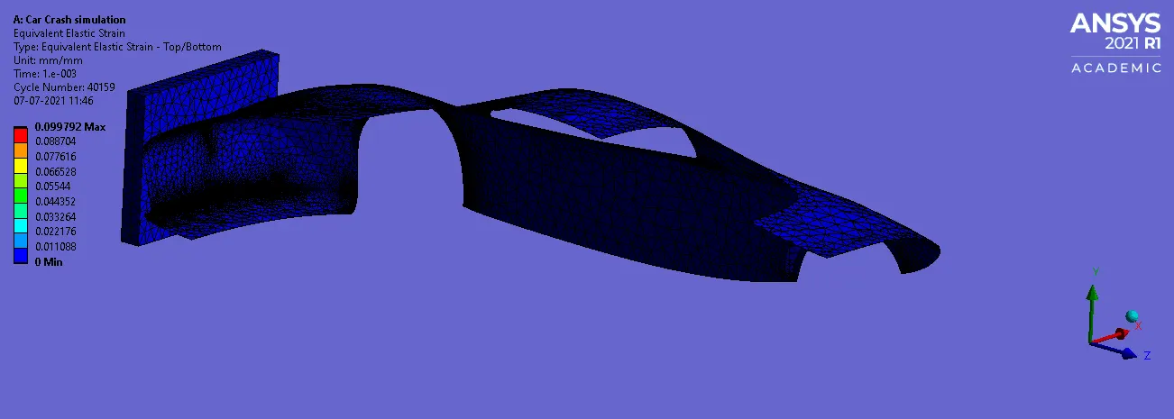
Fig 35: Equivalent Elastic Strain
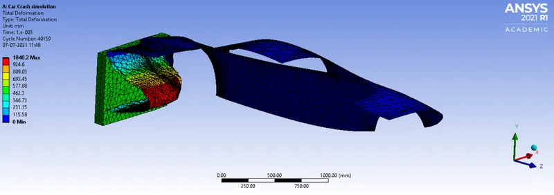
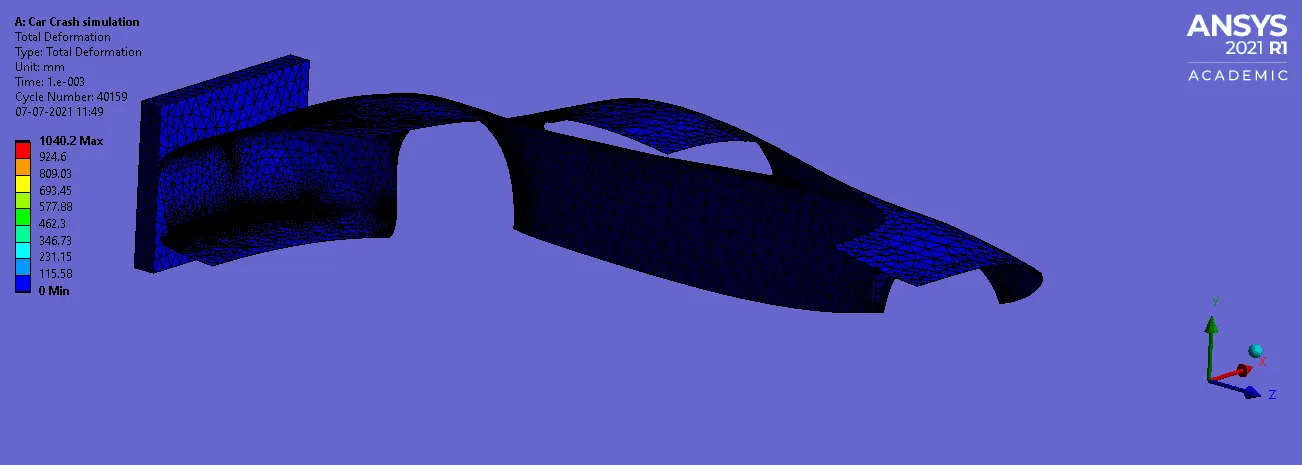
Fig 36: Total Deformation
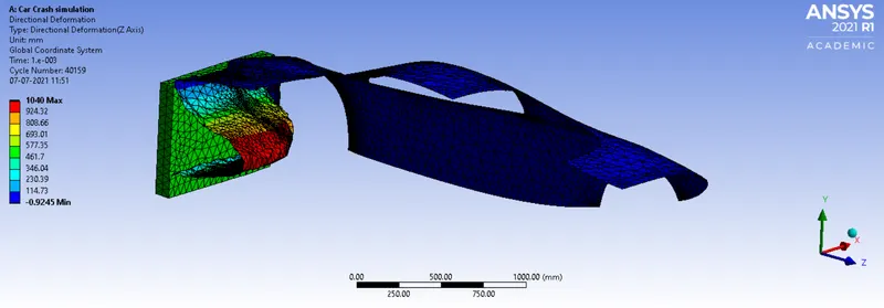
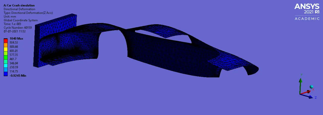
Fig 37: Directional Deformation about Z-Axis
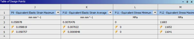
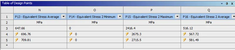
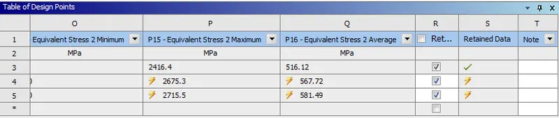
Parameter result:
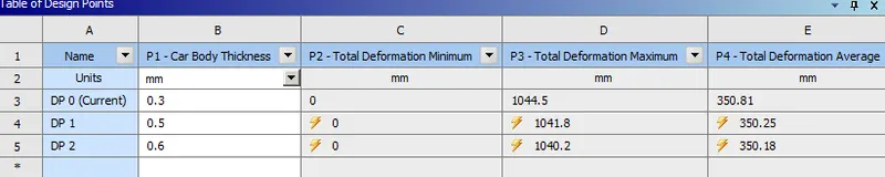
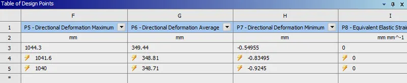
Tabular results:
| Sl No. | THICKNESS (mm) | Equivalent Stress (MPa) | Equivalent Stress in the car body (MPa) | Equivalent Elastic Strain | Total Deformation (mm) | Directional Deformation about Z-Axis (mm) |
| 1. | 0.3 |
Max: 11683 Min: 0 |
Max: 2416.4 Min: 0 |
Max: 0.058978 Min: 0 |
Max: 1044.5 Min: 0 |
Max: 1044.3 Min: -0.54955 |
| 2. | 0.5 |
Max: 11652 Min: 0 |
Max: 2675.3 Min: 0 |
Max: 0.058819 Min: 0 |
Max: 1041.8 Min: 0 |
Max: 1041.6 Min: -0.83495 |
| 3. | 0.6 |
Max: 11641 Min: 0 |
Max: 2715.5 Min: 0 |
Max: 0.058757 Min: 0 |
Max: 1040.2 Min: 0 |
Max: 1040 Min: -0.9245 |
CONCLUSION:
From the above results we can conclude that the Highest equivalent stress of 11683MPa is experienced, when the thickness of car is assigned with 0.3mm. The Lowest equivalent stress of 11641MPa is experienced, when the thickness of car is assigned with 0.6mm. From the above statement we can say that the increase in thickness will reduce the rate of equivalent stress generated. The equivalent elastic strain remains almost same in all three conditions. The Highest Total deformation of 1044.5mm is experienced, when the thickness of car is assigned with 0.3mm. The Lowest Total deformation of 1040.2mm is experienced, when the thickness of car is assigned with 0.6mm. From the above statement we can say that the increase in thickness will reduce the rate of Total Deformation generated.
Link: https://drive.google.com/drive/folders/1UoVe2487JRAB_eduUWOop5jipLRin3Cl?usp=sharing