Week 3 Verification of Weld Joints
Verification of Weld Joints
OBJECTIVE: The objective of this challenge is to perform a static structural analysis and to Simulate three different types of welding by using three different weld materials such as Stainless Steel, Aluminium Alloy and Bronze cast. And to run the simulation for a load of 15000N that is to be applied at the rectangular hole in the small plate, as well as for each case, to find out the Directional Deformation and equivalent strain experienced by the setup and to Identify the weld joint that experiences the highest equivalent stress in each case and compare the results for all three cases.
SOFTWARE USED: ANSYS Workbench 2021 R1 and ANSYS Mechanical for Analysis.
INTRODUCTION:
A welding joint is a point or edge where two or more pieces of metal or plastic are joined together. They are formed by welding two or more workpieces (metal or plastic) according to a particular geometry. There are five types of joints referred to by theAmerican welding society: butt, corner, edge, lap, and tee. These configurations may have various configurations at the joint where actual welding can occur.
Fig 1: Welding Joint
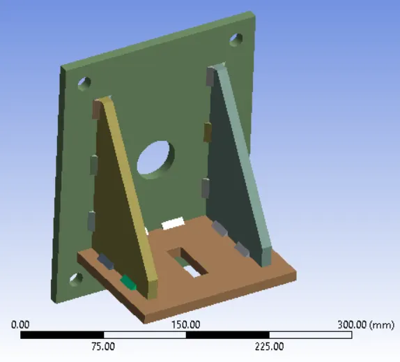
Fig 2: CAD Model
The CAD Model consists of Two plates, two ribs and and 26 weld joints. Holes are provided to the bigger plate for providing the support with the wall and a small rectangular hole is provided to the smaller hole, for adding the load to it. The two plates and two ribs are connected each other by 26 weld joints.
PROCEDURE:
1. Open the ANSYS Workbench software. Under the Analysis system select the Static structural and wait for few seconds to pop up the window, which contains Engineering data, Geometry, Model, setup, Solution and Results.
2. Rename the static structural as Weld Joints.
3. Under geometry import the Weld Joints model.
4. Update the model by right click and edit the Model for Preprocessing.
5. Wait for few seconds and ANSYS Mechanical will open as shown below.
Fig 3: CAD Model of the Weld Joint
6. Assign the material to the model, By classifying the required needs into three cases, And assign material to the model based on the cases.
Weld Material used:
Case 1. Stainless Steel: In this case, the material of the plates must also be the same. Use Stainless steel for both weldments and plates. No need to add flux to the weldments.
Case 2. Aluminium Alloy:The material to be chosen for this case is Aluminium alloy(high strength, wrought). [Plate material to be used is stainless steel]
Case 3.Bronze: In order to simulate "Brazing", we should use bronze as the weld material. Assign Stainless Steel to both plates and Copper to the "Ribs".
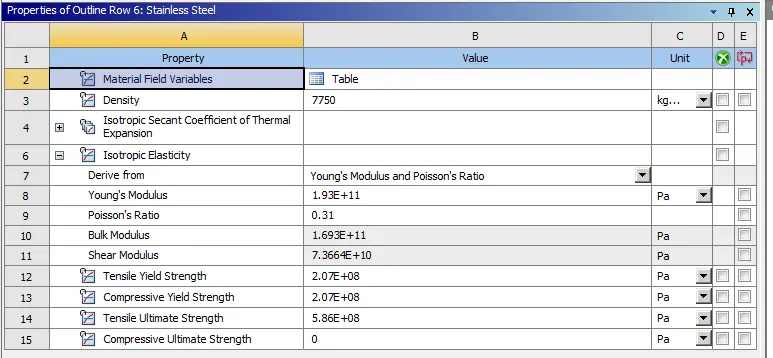
FIG 4: Material properties of a stainless steel
FIG 5: Material properties of an Aluminum Alloy
FIG 6: Material properties of a Bronze cast
7. Frictional contact between the two Plates and the two ribs are Defined with a frictional coefficient of 0.3.
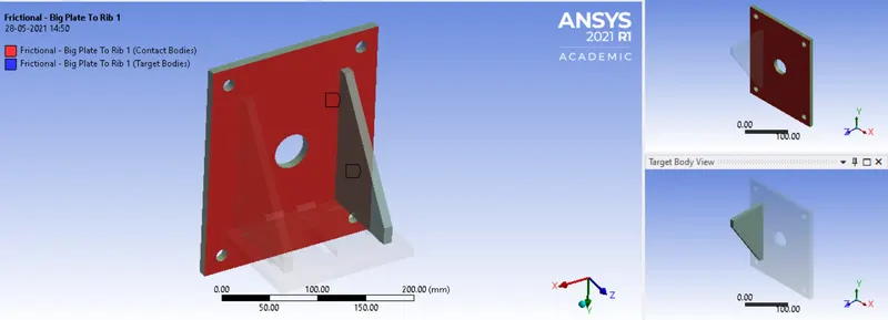
Fig 7: Frictional contact between the Plate and the rib
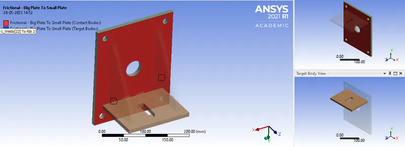
Fig 8: Frictional contact between the two Plate
8. Insert a fixed support at the holes to the Bigger plate in order to act as fixed. So click on static structural go to insert and select fixed support. Then select the holes.
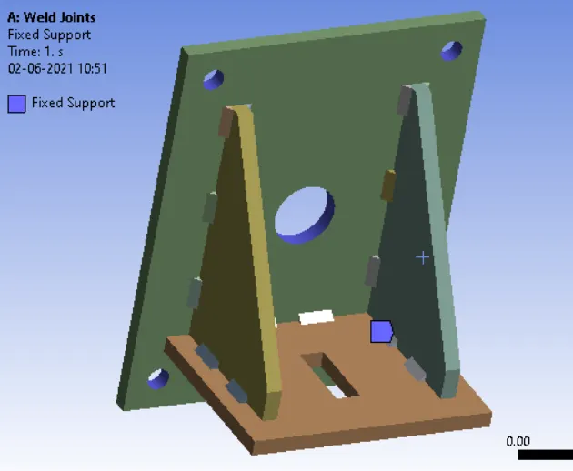
Fig 9: Fixed Support
Then apply a force of 15000N at the rectangular block by clicking on static structural go to insert and select Force. Then select the rectangular block and apply the force=15000N
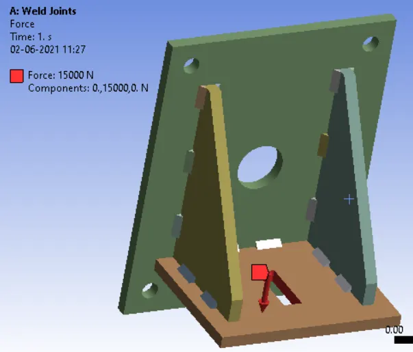
Fig 10: Applying Fore
9. In ANSYS automatic mesh will be performed with Default mesh size and change the mesh size as 10mm. (based on grid dependency test reducing the element size further doesnot effect the result and element size 10mm is asssigned.) (i.e Ansys student version will have a limted number of elements and nodes.) Apply the mesh size of 7mm to the two plates by selecting body sizing.
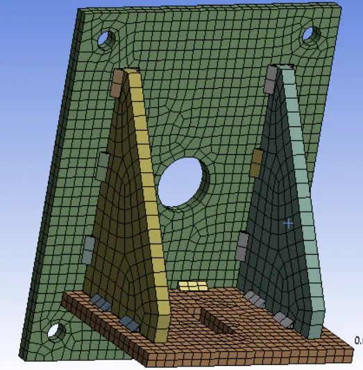
Fig11: Meshing
Be aware of ANSYS Student Edition and don't go beyond the size limit. The below figure shows the mesh size along with its number of nodes and elements.
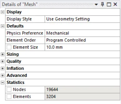
Fig 12: statistics of meshing
10. As it is a solid structure we have to change the 2D Element to 3D Element. So click on mesh and select the insert option. Under insert option select the method and slect the gemetry as well as under the method, select the tetrahedrons.
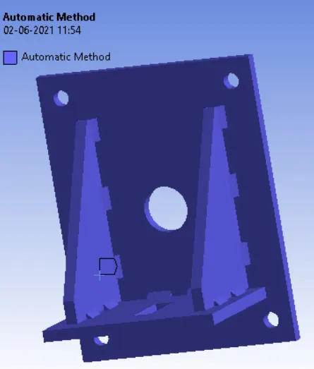
FIG 13: Selecting Bodies for 3D Meshing
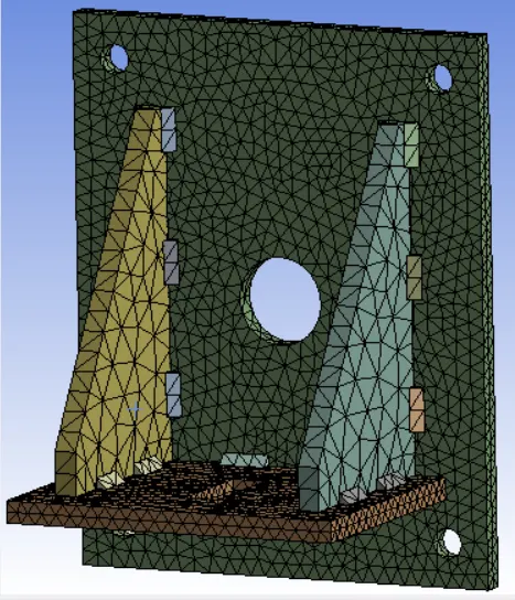
FIG 14: 3D Meshing
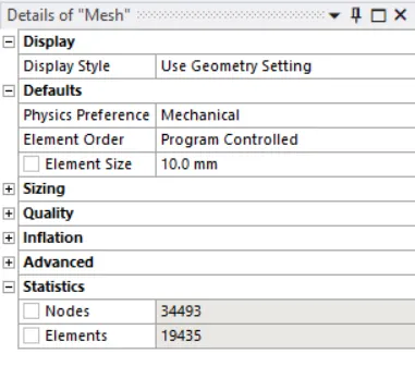
Fig 15: statistics of meshing
11. Analysis settings Change no. of steps as 1, auto time as program control, large deflection on, solver type as program controlled.
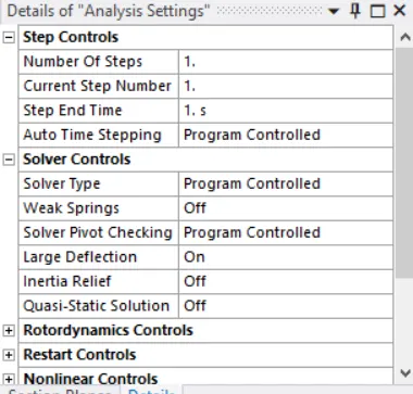
FIG 16: Analysis settings
12. Now request for the outputs such as equivalent stress, equivalent elastic strain, directional deformation, strees and contact Tool.
14. SOLVE the solution and we can see the simulation run under soluion information.
FIG 17: Solver output
CASES:
Case 1. Stainless Steel: In this case, the material of the plates must also be the same. Use Stainless steel for both weldments and plates. No need to add flux to the weldments.
Case 2. Aluminium Alloy:The material to be chosen for this case is Aluminium alloy(high strength, wrought). [Plate material to be used is stainless steel]
Case 3. Bronze: In order to simulate "Brazing", you should be using bronze as the weld material. Assign Stainless Steel to both plates and Copper to the "Ribs".
RESULT:
Simulation results for case-1 the material of the plates, ribs and weldments are same (i.e Stainless steel)
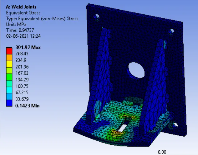
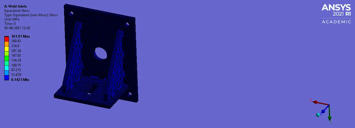
Fig 18: Equivalent Stress
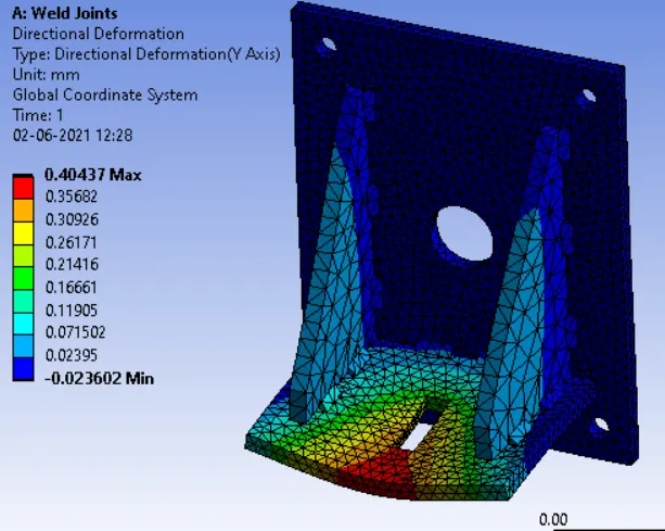
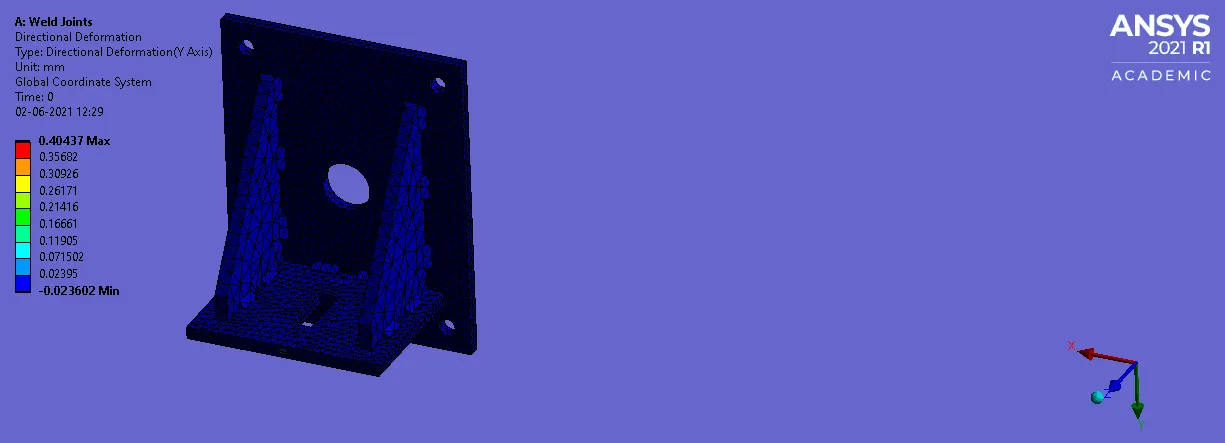
FIG:19 DIRECTIONAL DEFORMATION (Y-Axis)
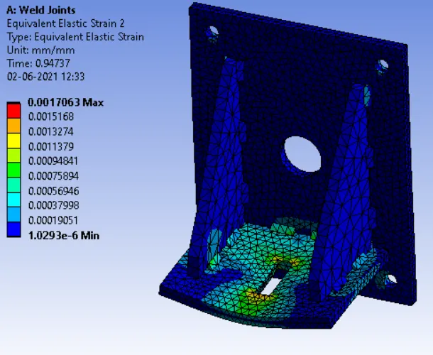
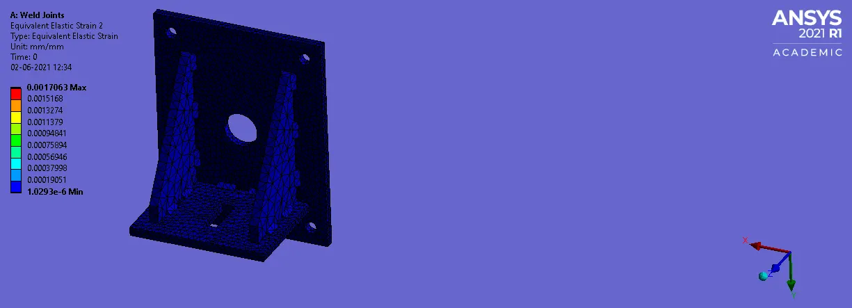
Fig 20: Equivalent Strain
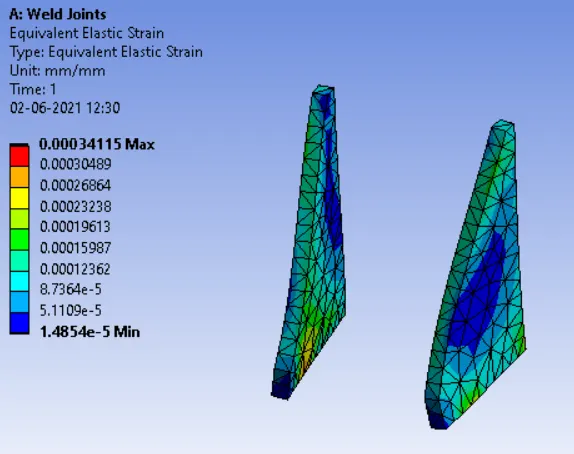
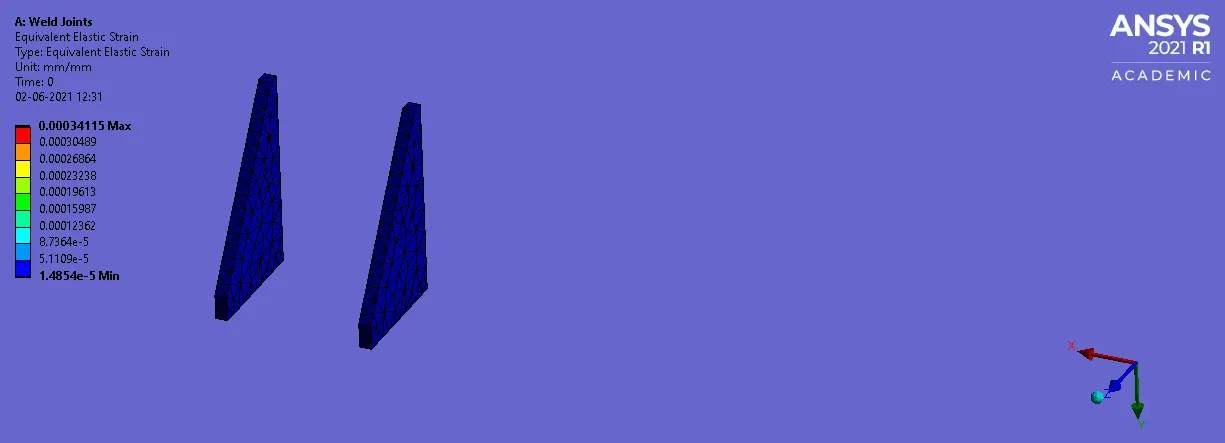
Fig 21: Equivalent Strain of ribs
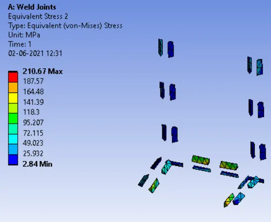
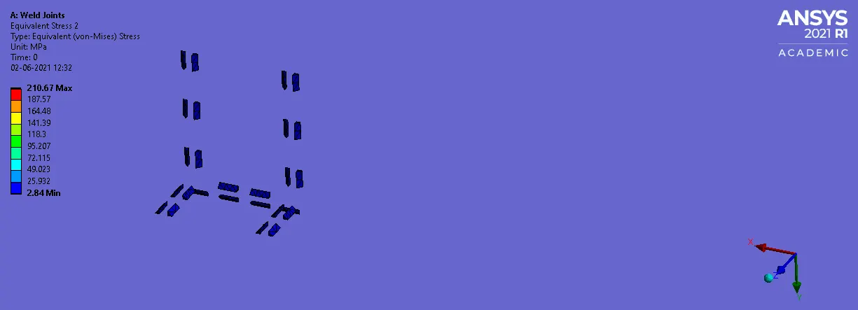
Fig 22: Equivalent Stress of weldments
Case 2. Simulation results of aluminium Alloy:The material to be chosen for this case is Aluminium alloy(high strength, wrought). [Plate material to be used is stainless steel]
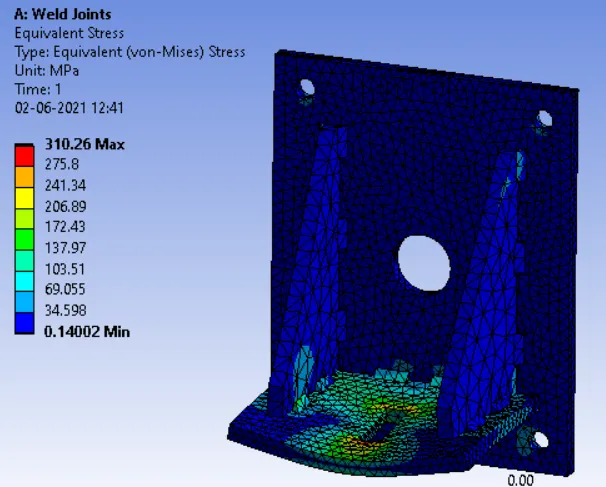
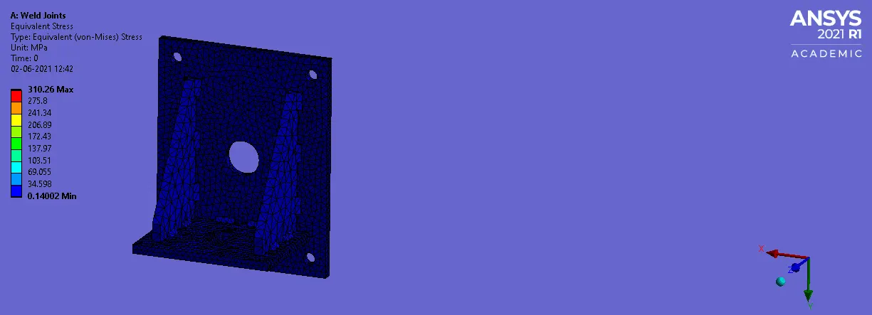
Fig 23: Equivalent Stress
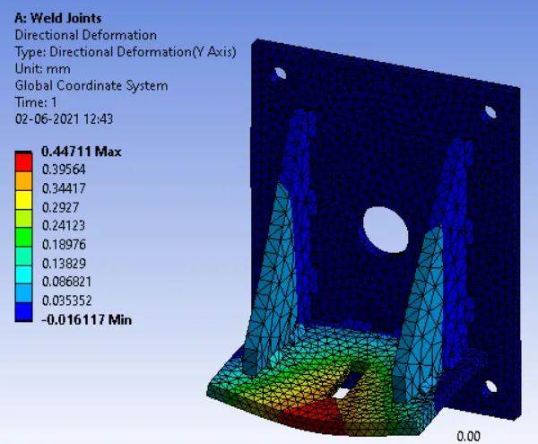
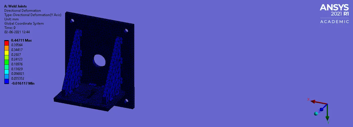
FIG: 24 DIRECTIONAL DEFORMATION (Y-Axis)
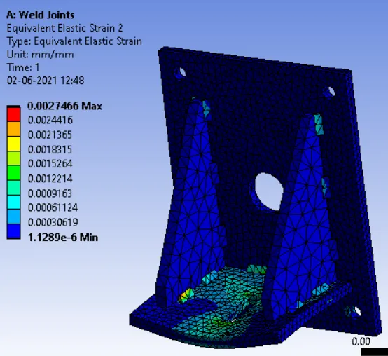
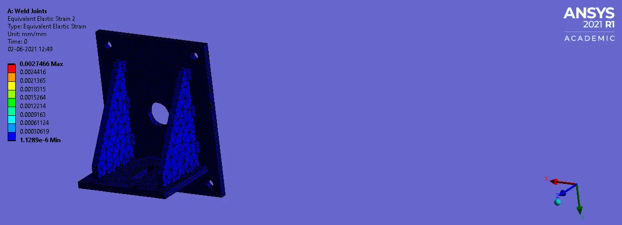
Fig 25: Equivalent Strain
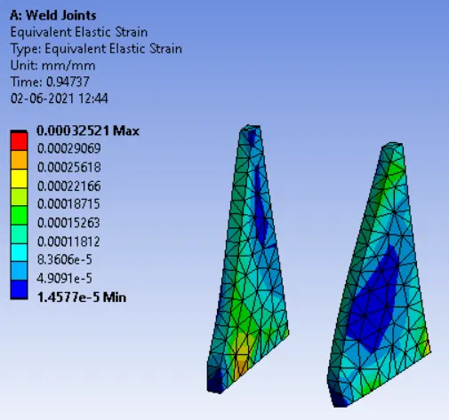
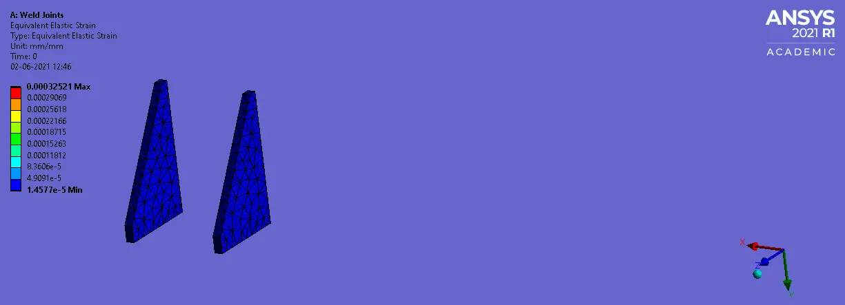
Fig 26: Equivalent Strain of ribs
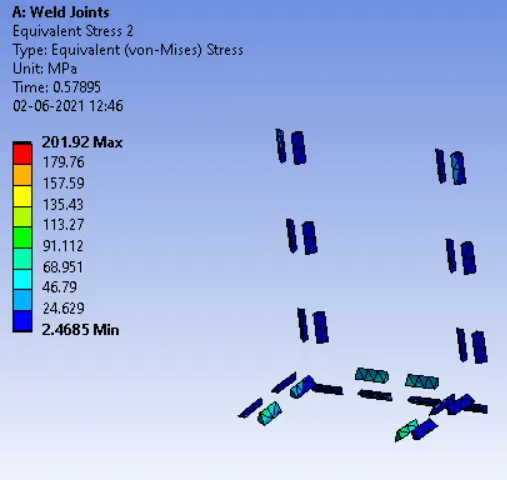
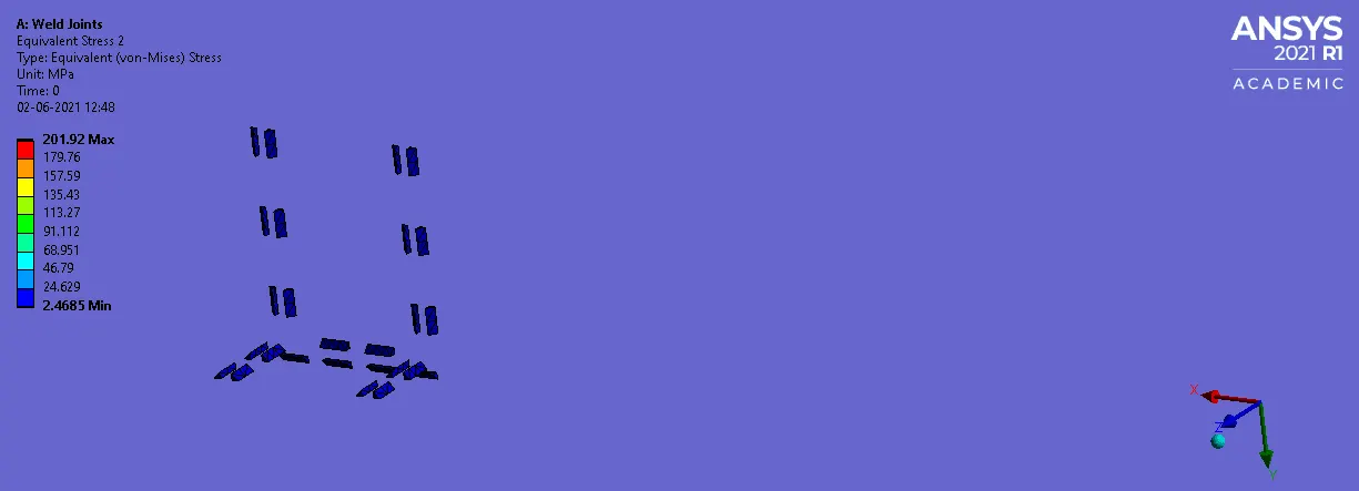
Fig 27: Equivalent Stress of weldments
Case 3. Simulation results of Bronze: In order to simulate "Brazing", we should be use bronze as the weld material. Assign Stainless Steel to both plates and Copper to the "Ribs".
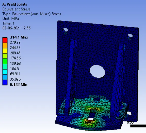
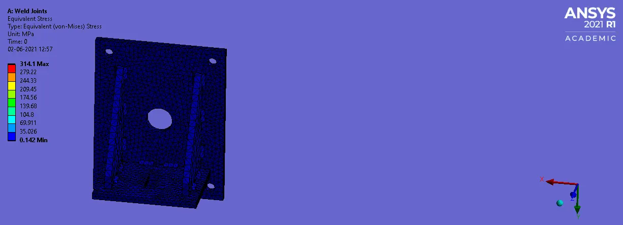
Fig 28: Equivalent Stress
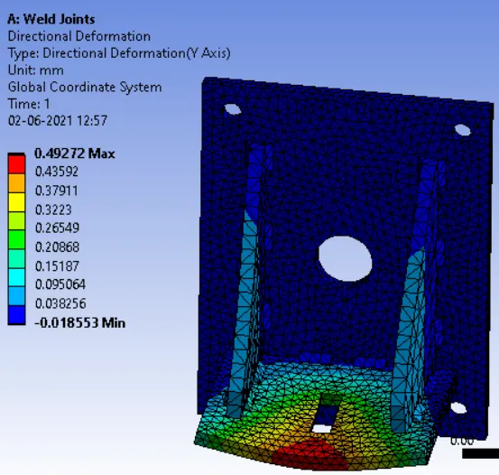
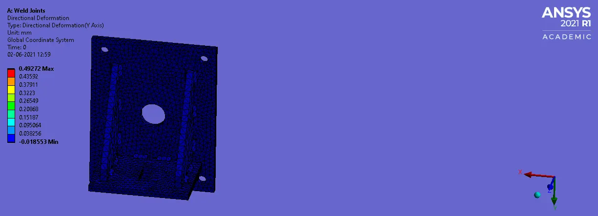
FIG: 29 DIRECTIONAL DEFORMATION (Y-Axis)
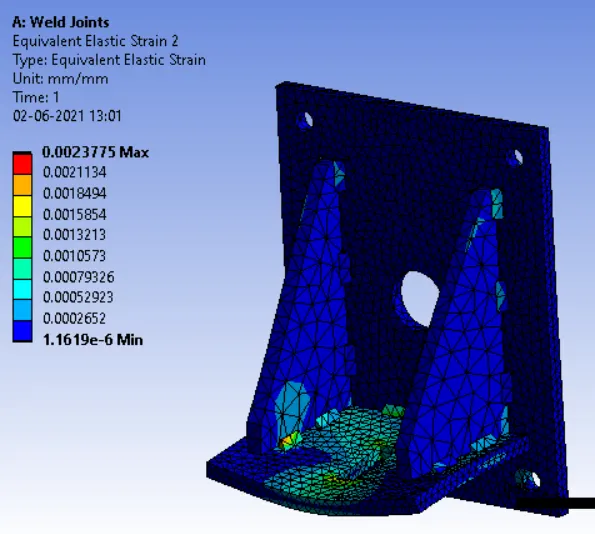
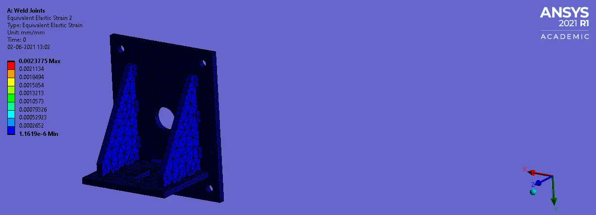
Fig 30: Equivalent Strain
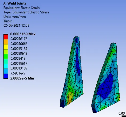
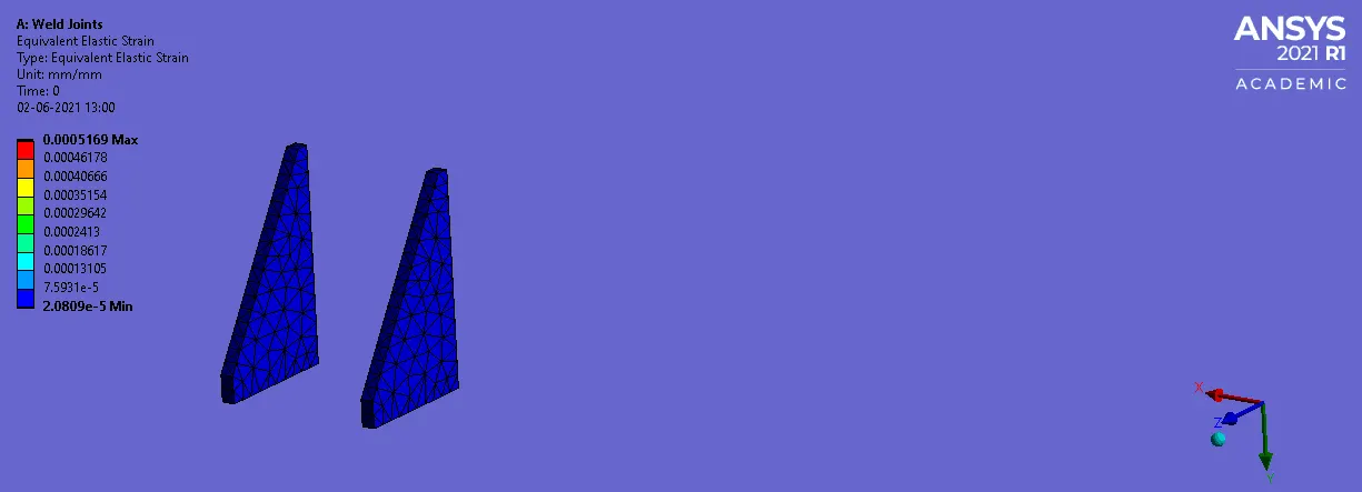
Fig 31: Equivalent Strain of ribs
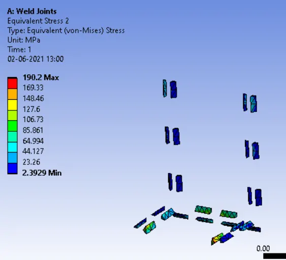
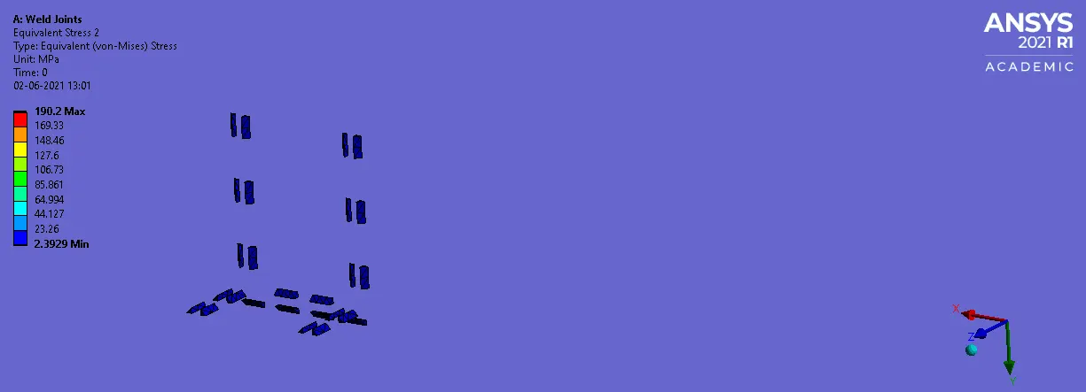
Fig 32: Equivalent Stress of weldments
Camparism of results:
| MATERIAL | EQUIVALENT STRESS (MPa) | DIRECTIONAL DEFORMATION (Y-Axis) (mm) | STRAIN | RIB STRAIN | EQUIVALENT STRESS AT WELDMENTS (MPa) |
| Stainless Steel |
MAX: 301.97 MIN: 0.143 |
MAX: 0.40437 MIN: -0.023602 |
MAX: 0.0017063 MIN: 1.0293e-6 |
MAX: 0.00034115 MIN: 1.4854e-5 |
MAX: 210.67 MIN: 2.84 |
| Aluminum |
MAX: 310.26 MIN: 0.14002 |
MAX: 0.44711 MIN: -0.016117 |
MAX: 0.0027466 MIN: 1.1289e-6 |
MAX: 0.00032521 MIN: 1.4577e-5 |
MAX: 201.92 MIN: 2.4685 |
| Bronze |
MAX: 314.1 MIN: 0.142 |
MAX: 0.49272 MIN: -0.018553 |
MAX: 0.0023775 MIN: 1.1619e-6 |
MAX: 0.005169 MIN: 2.0809e-5 |
MAX: 190.2 MIN: 2.3929 |
The above tabular data shows the variations in the equivalent stress and directional deformation of various material such as Stainless Steel, Aluminium and Bronze. Bronze material experiences more stress and directional deformation where compared with case-1 and case-2.
Conclusion:
From the above result we can conclude that the equivalent stress and maximum directional deformation takes place in Case-3. The maximum deformation takes place in case-3 because in this case the material copper and bronze will have low yield strength when compared to stainless steel and Aluminium.
From case-1, the ribs, plates and weldments are assigned with same material as stainless steel and experiences more stress at weldments due to high yield strength of material as well as in case-2, the stress at weldment is high when compared with case-3.
The Stainless steel will have high equivalent stress when compared with case-1 and case-2. the aluminum material will have high equivalent stress when compared with case-3.
The usual causes of material failure are incorrect materials selection, incorrect processing, incorrect manufacturing procedures, inadequate design or incorrect use. Fracture is the separation of a body into two or more pieces as a result of an imposed stress. Here the alumium material will not fail as the FOS of this material is 1.17 when compared with other two. FOS= YIELD STRESS/WORKING STRESS,
FOS of aluminium = 363/310.26 = 1.17.
Grid depenency test will be important for selecting the suitable mesh size.
LINK: https://drive.google.com/drive/folders/1CI_tXeu6axHGWSdpYmm-H2Jfj0SKpUjb?usp=sharing