Week -2
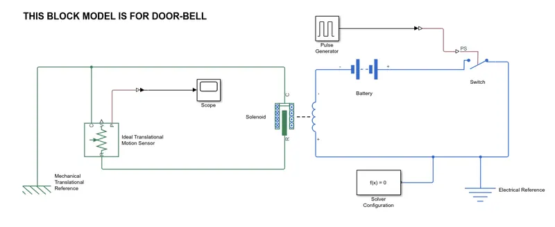
1) Simulink block mode for Doorbell using solenoid :
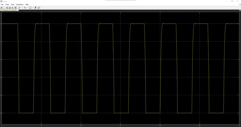
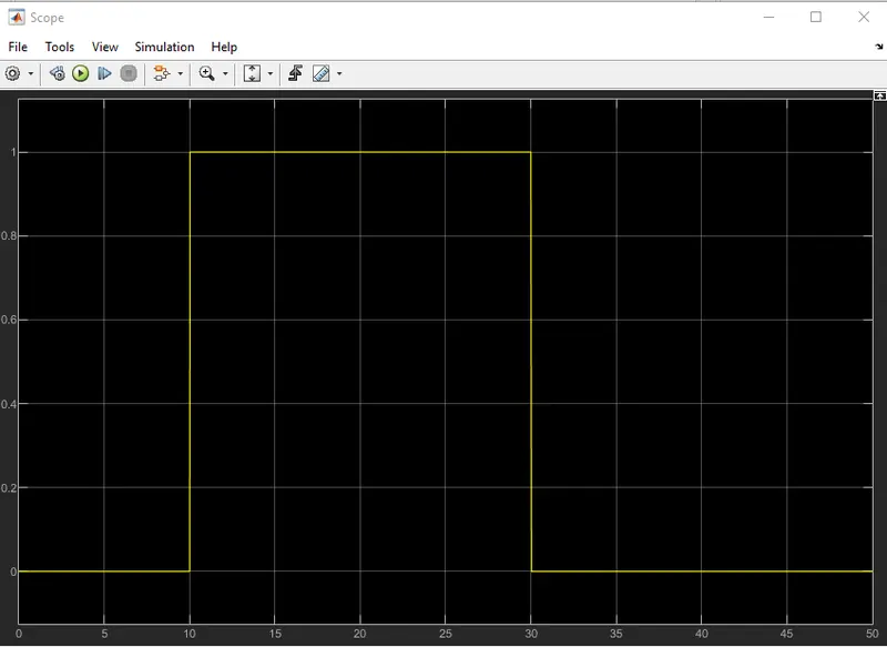
Output / data from the scope :
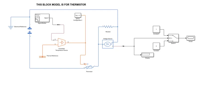
2) Simulink block mode for thermistor :
Output / data from the scope :
Report :
1) For doorbell using solenoid :
- In this model , the requirement is "switch is closed for 2 seconds and then released" , i have used a pulse generator for this purpose .
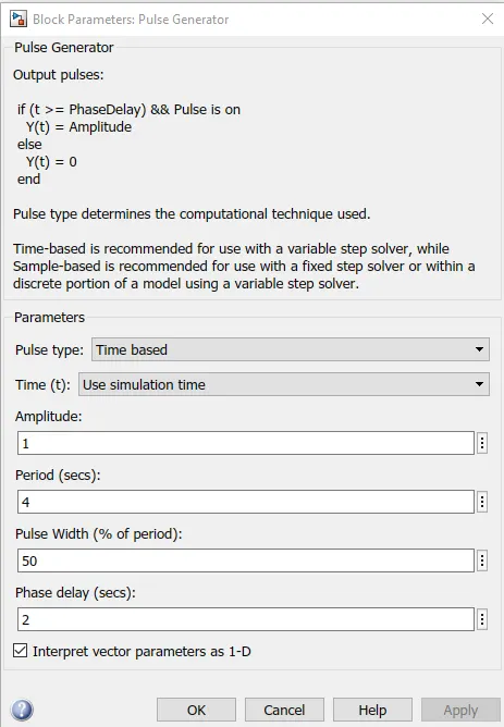
- I congigured the pulse as per the requirement by altering the value of amplitude , period , pulse witdh & phase delay.
- Then by using a simulink to ps converter , i converted the output from the pulse generator n gave that to a switch.
- Now the switch will act acording to the pulse generator.
- The switch is connected with a battery and with the electro-magnet part of a solenoid.
- The plunger which is the mechanical part of the solenid , will move by the activation of the electro-magnet.
- To detect the motion of the plunger , i have used a translational motion sensor , which is connected to the plunger of the solenoid.
- To get the output from the sensor , i first converted the sensors ps signal to simulink by simulink-ps converter.
- And used a scope to display the output.
- A solver is provided to the model which helps in understanding the system that whether it is a continous or discrete system and solves according to that.
- Electrical reference & mechanical referecne are used to ground all the circuits in this model.
output :
- The plunger movement in here represents the ringing of the bell , we can see in the graph ,the bell rings exactly as per the requirement.
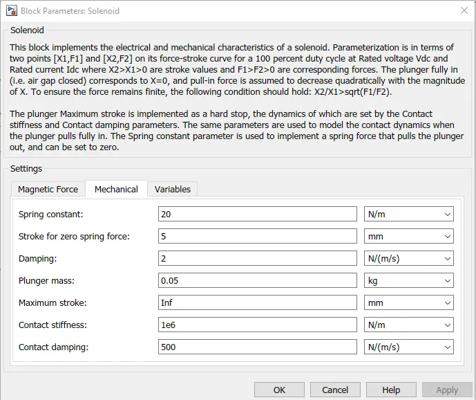
- configured parameters of pulse generator and the solenoid for the desired out put :
pulse generator :
solenoid :
2) For thermistor :
- In this model , the requirement is , for temperature source: 20 °C from 0 to 10 seconds, 27 °C from 10 to 30 seconds, 23 °C from 30 to 50 seconds the Fan conditions: ON if the temperature above 25 °C, OFF otherwise.
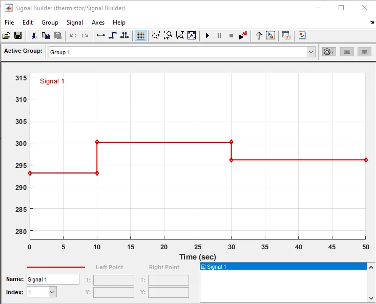
- I have used a signal builder block for the tempreture source input , and created a signal as per the requirement for the tempreture.
- For the tempreture source i have used a controlled tempreture source block , and connected it with the signal builder output.
- The thermistor is powered by a battery , its heat sensor is connected to the controlled tempreture source output.
- The thermistor reads the temp data , and converts that to electrical signal.
- A resistor and a voltage sensor block is connected to the thermistor , for reading the electrical signal.
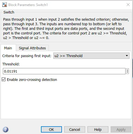
- Then the voltage sensor output is connected to a on-off switch block , by giving a threshold valuse to the switch from voltage sensor data , it ultimately decides wheather to turn on/off the fan.
- A solver is provided to the model which helps in understanding the system that whether it is a continous or discrete system and solves according to that.
- Electrical reference & thermal referecne are used to ground all the circuits in this model.
- configured parameters of signal builder , simulink-ps converter , switch for the desired out put :
signal builder :
simulink-ps converter :
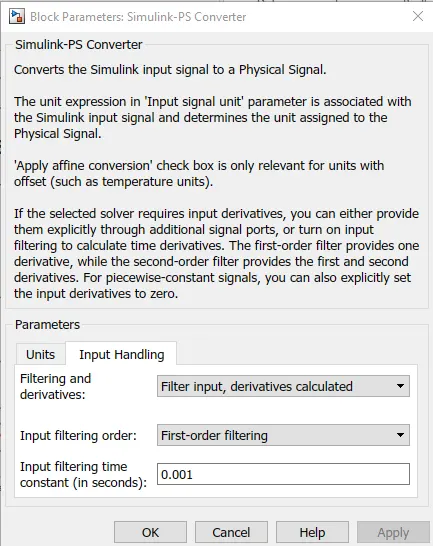
switch :