Week 8 - Challenge 6 - Core & Cavity Design
AIM : Creation of a Core and cavity blocks for the switch bezel Plastic component.
WHAT IS TOOLING AXIS : The direction in which the mold or core and cavity opens is the tooling axis.
HOW TO CREATE A TOOLING AXIS :
1) Before creating a tooling axis , as a preventive measure check the Connectivity of Class-A surface. it can be done by using the "join" or "boundary" command. using these command we can identify any unnecessary openings of the class-A surface.
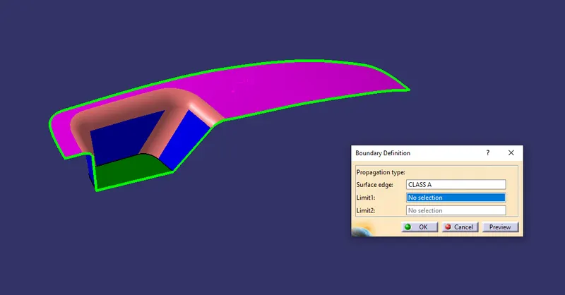
no unnecessary openings are found.
2) visually analyse which is the best possible way to create the tooling axis , considering avoiding side cores, easy ejection of component from core, easy flow of molten plastic inside the cavity.

along 'y' tooling axis is not possible , along 'x' tooling axis is possible but considering two bigger flat surfaces are present in the 'z' direction , we will try to create tooling axis along 'z'.
3) In the pocket area we have 3 walls , we will make sure that every wall is clearing with the tooing axis , to confirm that we will perform Bisecting method.
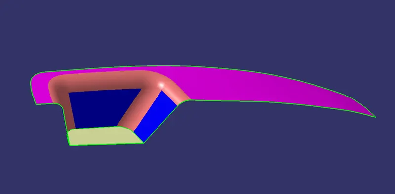
we are planing to create tooling axis along 'z' so we will intersect the class-A with 'yz' & 'zx' plane.
4) Extracted the base surface because all the three walls are connected to this surface , and made a point in the center of the surface.
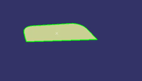
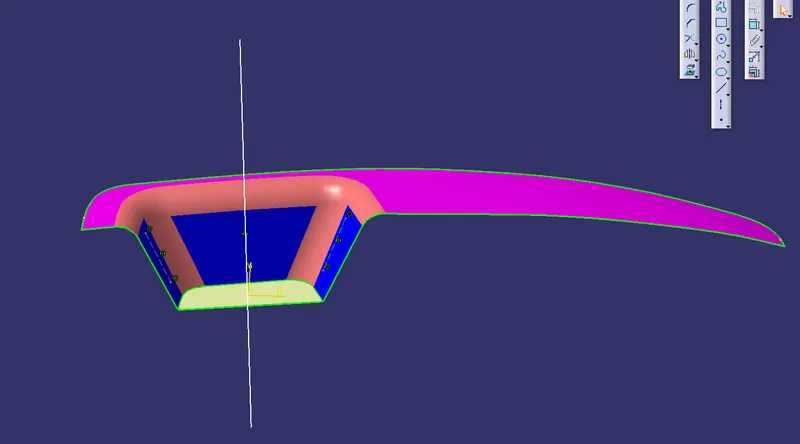
5) For 'yz' plane created a sketch and intersected the class-A , for the two walls in this plane , made two lines along the walls and then bisected them to find the partial tooling axis.
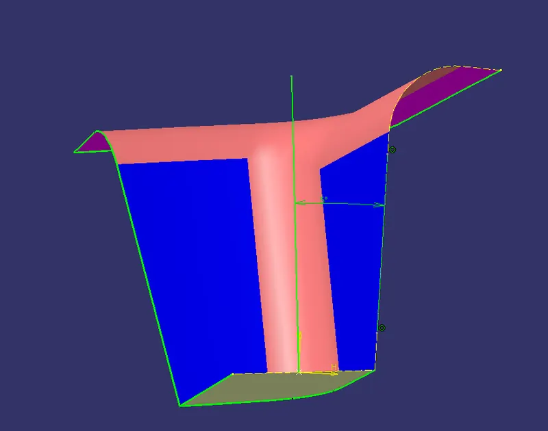
6) For 'zx' plane created a sketch and intersected the class-A , because here only one wall is present , considering the draft angle created one line along the wall and another in the middle of the surface with an angle of (3-6 degree) , and that is another partial tooling axis.
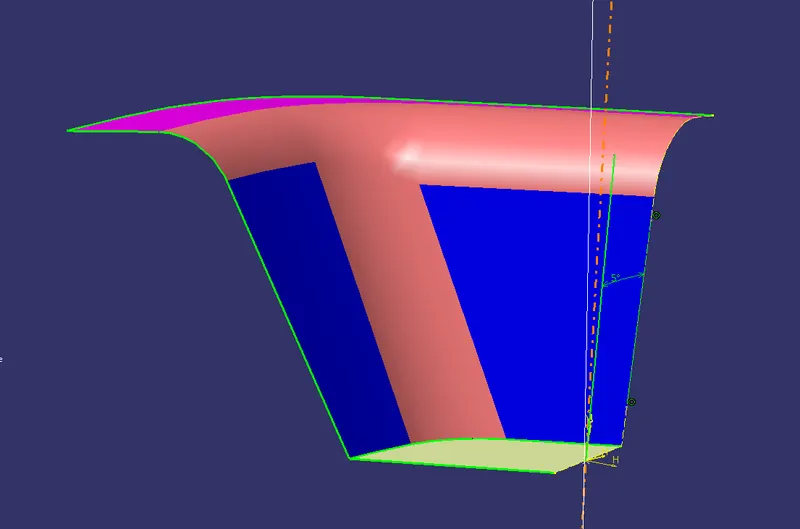
7) Finally bisected the two partial tooling axis to find the actual tooling axis.
Draft analysis :
After determining the tooling axis , Draft analysis is done.draft analysis is used to check whether the desired draft angle is maintained or not. Compass is used in the draft analysis command to define the draft direction. as an output of this operation , we will be receving a colored range table , which will clearly show which surface of the component is getting cleared or not with the required draft angle , and with that result we can modify the surface.
Draft analysis for class-A :
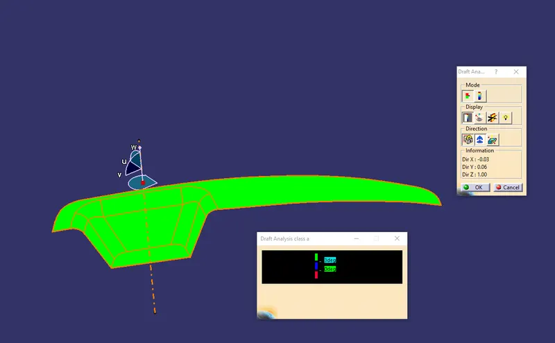
every surface is clearing with 3 degree draft angle .
Draft analysis for final plastic component :
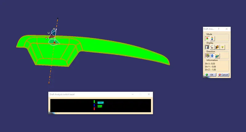
every surface is clearing with 2.9 degree draft angle .
Core and cavity block creation:
parting line :
In injection molding, the parting line refers to the line where the two halves of the mold meet and separate to allow for the removal of the molded product. When molten plastic is injected into the mold, it flows into the cavity created by the two halves of the mold. Once the plastic has solidified, the mold halves are separated along the parting line, and the molded product is ejected.
The parting line can sometimes leave a small raised line or seam on the finished product where the two halves of the mold met. This can be minimized by designing the mold with a smooth parting line and using appropriate injection molding techniques. The parting line can also affect the product's overall quality, strength, and appearance, so it is important to carefully consider the parting line location and design during the mold-making process.
parting surface :
In injection molding, the parting surface is the area of the mold where the two halves of the mold meet and separate to allow for the removal of the molded product. The parting surface is the specific location where the mold cavity and the mold core come together.
When designing an injection mold, the parting surface is a critical feature that must be carefully considered. It is essential to design the parting surface in such a way that it creates a clean, smooth separation between the two halves of the mold, allowing the molded product to be removed easily without any damage.
The location of the parting surface also affects the appearance and quality of the molded product. Ideally, the parting surface should be located in an inconspicuous location on the finished product, such as along a natural seam or edge.
The design and placement of the parting surface can impact the efficiency of the injection molding process and the quality of the final product. Therefore, careful attention must be paid to the parting surface during the design and manufacturing of the injection mold.
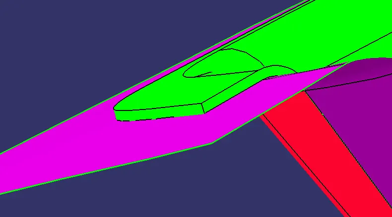
with the draft analysis we can see that the a & c surface is clearing with 2.9 degree draft angle , so we will create parting surface on the class b surface.
core block :
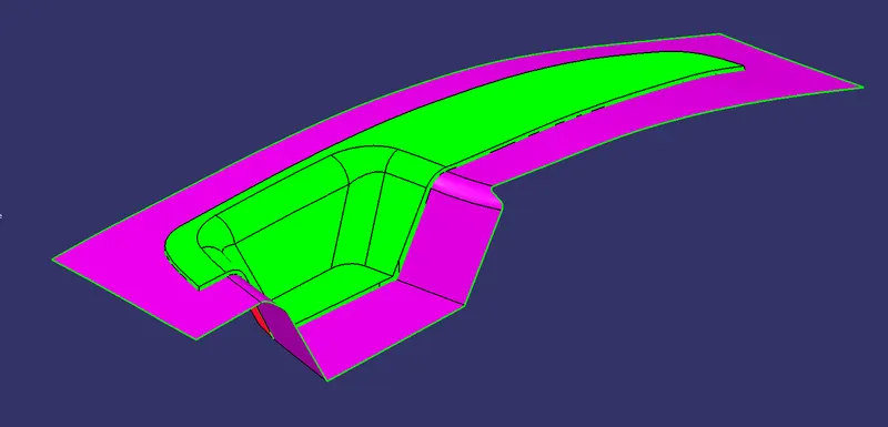
trimmed class a+c with class b.
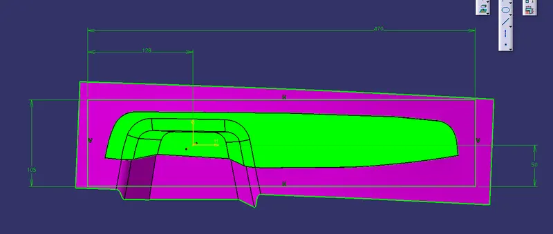
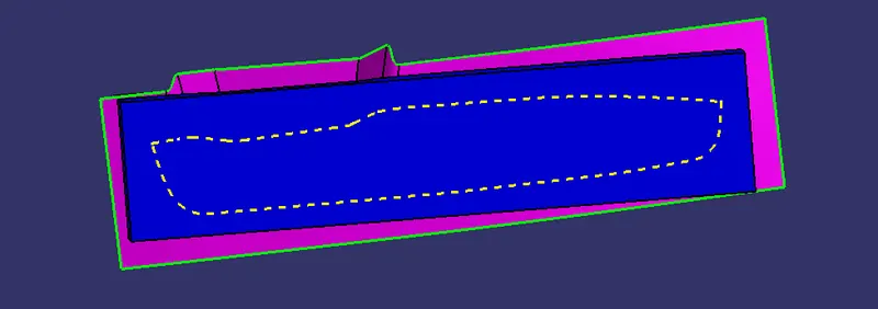
created a sketch in which a rectangle covers the part and the boundary of parting surface.
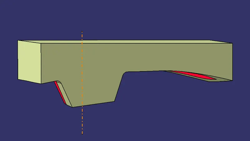
extruded the sketch along the tooling direction along core followed by trim with the parting surface with part followed by fill and join to create the surface for the core. then created a solid using close surface.
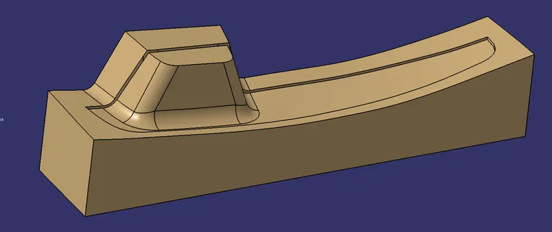
cavity block :
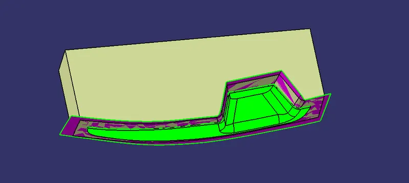
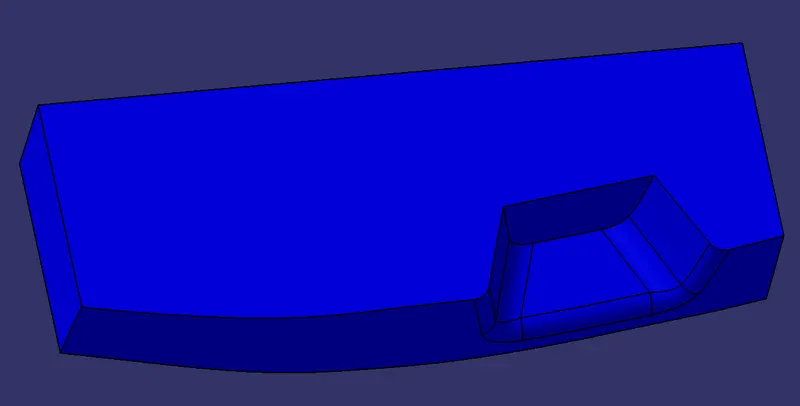
extruded the sketch along the tooling direction along cavity followed by trim with the parting surface with part followed by fill and join to create the surface for the core. then created a solid using close surface.
Tree Structure :
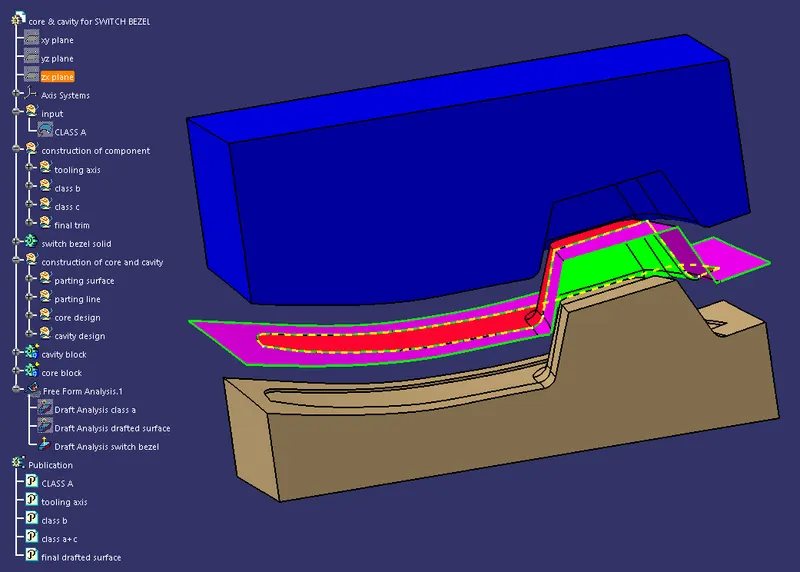
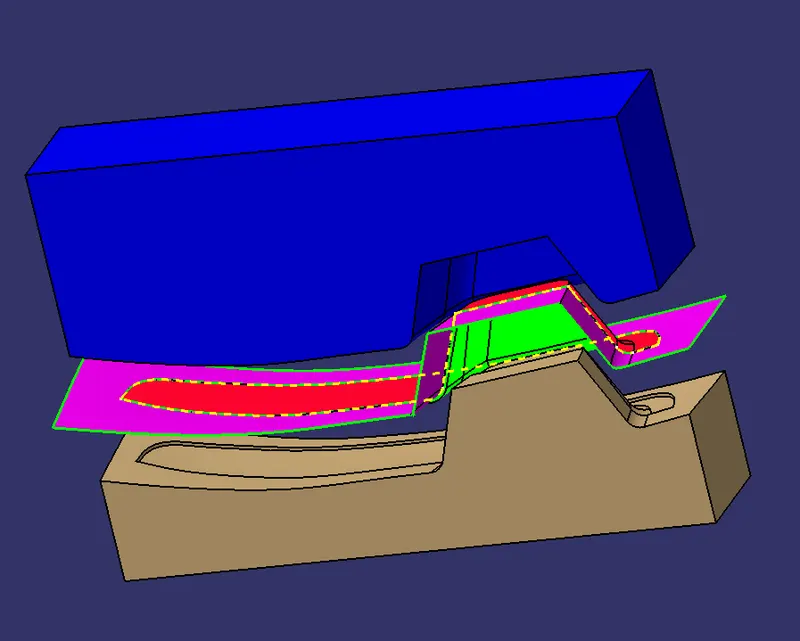
core and cavity blocks :
Isometric view :
Front view :
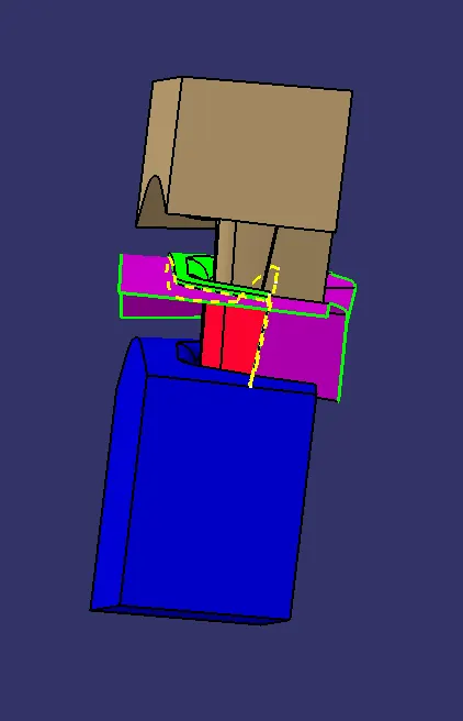
Side view :
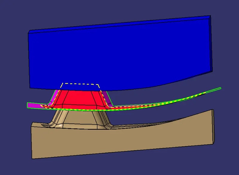
Top view :
version of software used :