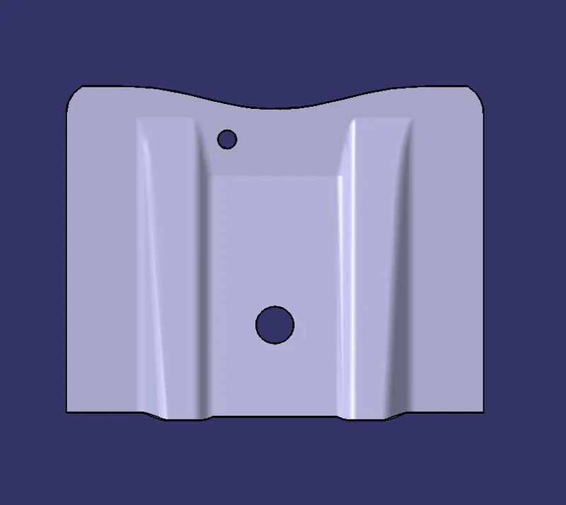
Week 8 - Challenge 1 - Base Bracket Design
AIM : Creation of a Base Bracket Plastic component of thickness 2.5mm through a given Class-A surface.
REPORT :
WHAT IS TOOLING AXIS : The direction in which the mold or core and cavity opens is the tooling axis.
HOW TO CREATE A TOOLING AXIS :
1) Before creating a tooling axis , as a preventive measure check the Connectivity of Class-A surface. it can be done by using the "join" or "boundary" command. using these command we can identify any unnecessary openings of the class-A surface.
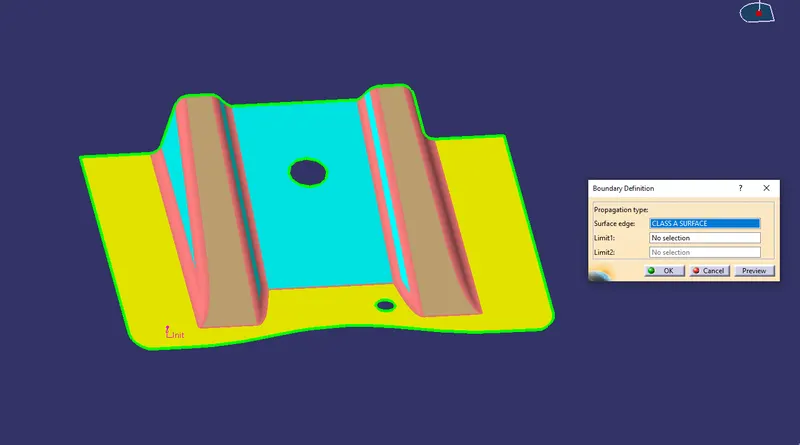
no unnecessary openings are found.
2) visually analyse which is the best possible way to create the tooling axis and create a dummy tooling axis along that direction , considering avoiding side cores, easy ejection of component from core , easy flow of molten plastic inside the cavity.
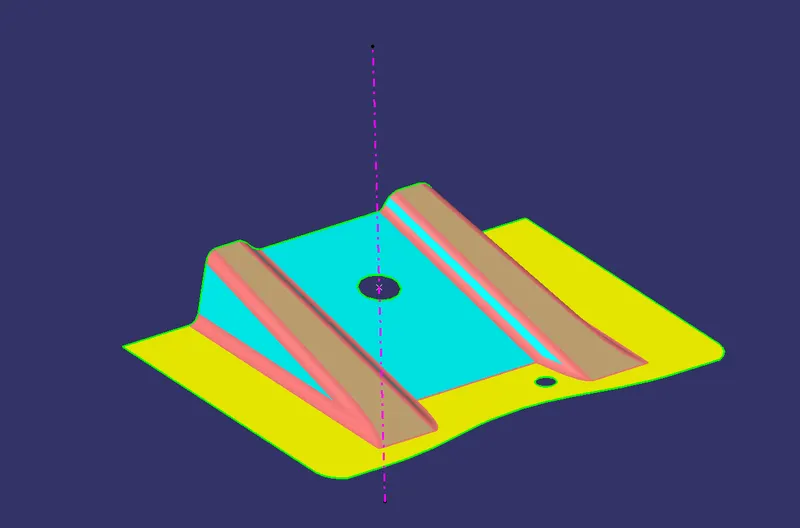
dummy axis is on 'z' direction , because in 'x' & 'y' direction we have to use side cores which is expensive and unnecessaryly complicated ,but in 'z' direction both the holes can be cleared and the bigger flat surface is easy for manufacturing.
3) A dummy tooling axis is not the proper tooing axis , but it helps to guide in the right direction of finding the main tooling axis.
4) Using "Bisecting method" we can find the main tooling axis or we can confirm whether the dummy tooling axis is the main tooling axis or not.
5) First intersect the class-A surface along the two planes related to the dummy axis . i.e if the dummy axis is in 'z' direction , then intersect the class-A surface with 'yz' and 'zx' plane.

over here we did not take intersection along 'zx' plane , because no suspicious surface is present in that plane.
6) look for any suspicious surface in the intersect which may or may not get clear by the dummy tooling axis , do it for both the plane , and then create lines along that surface.
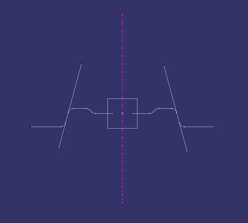
only these two surfaces are creating Suspicion.
7) Use the lines and a point as input in the 'bisect' command , if the two lines are parallel then it will show an error , which means tooling axis cant be created in that direction , if the lines are not parallel then it will form a line which bisects the input lines , perform this same operation with both the planes , and then again bisect the two output lines to find the main tooling axis.
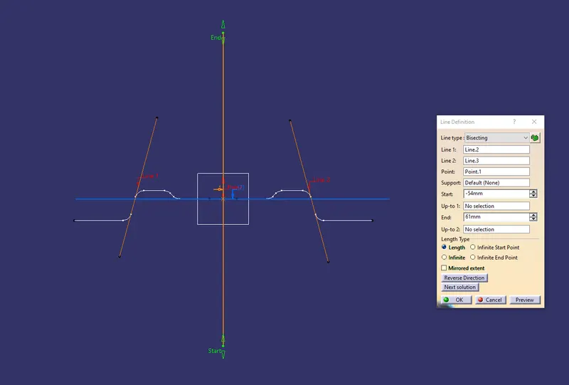
got the main tooling axis , which is same as dummy tooling axis
Draft analysis :
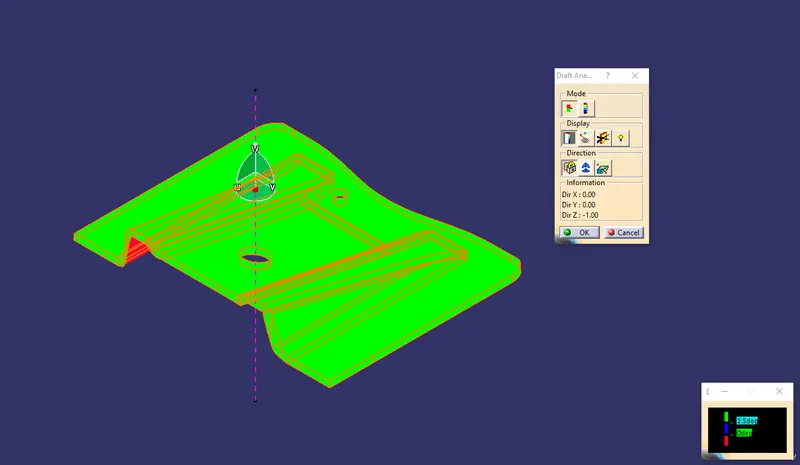
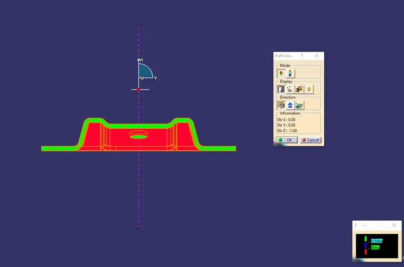
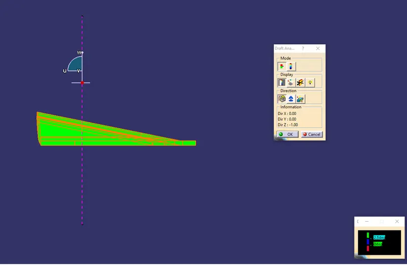
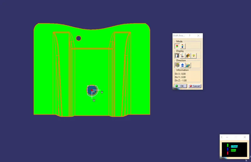
After determining the tooling axis , Draft analysis is done.draft analysis is used to check whether the desired draft angle is maintained or not. Compass is used in the draft analysis command to define the draft direction. as an output of this operation , we will be receving a colored range table , which will clearly show which surface of the component is getting cleared or not with the required draft angle , and with that result we can modify the surface.
for class-A :
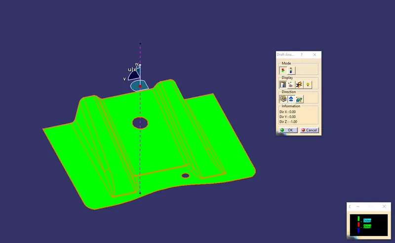
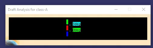
every surface is clearing with 3 degree draft angle .
for final plastic component :
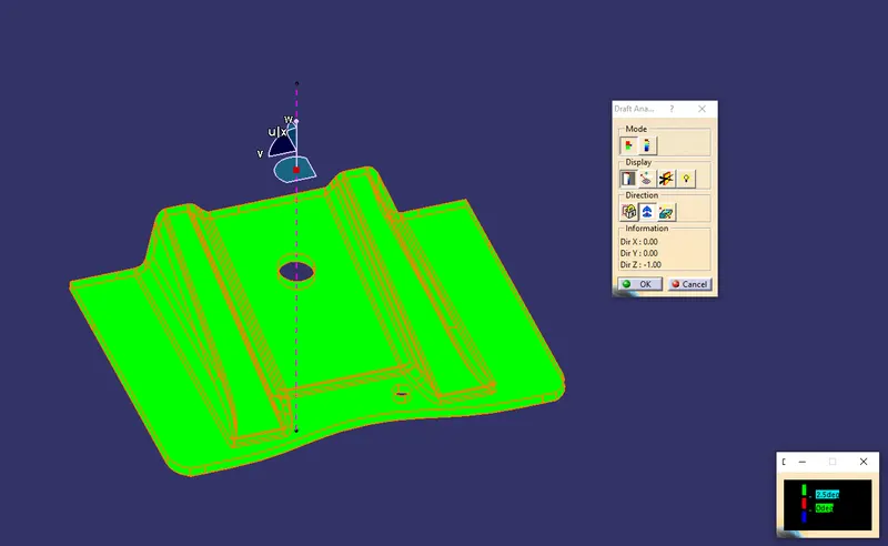
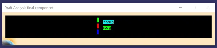
every surface is clearing with 2.5 degree draft angle .
creation of final component from class-A surface :
created a class-b surface from class-A surface by first extracting surfaces from class-a followed by untrim , follwed by extrapolate followed by trim , followed by offset and followed by final trim.
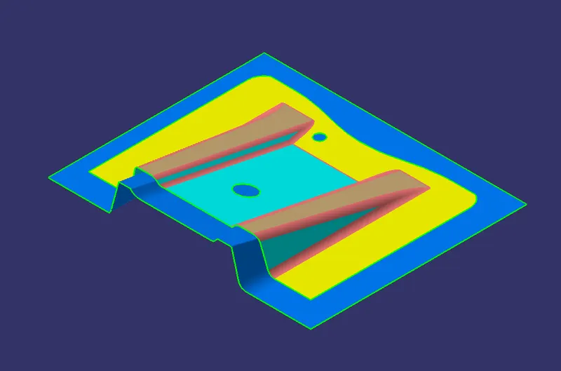
then created class-c from class-A by first taking the boundaries from class a then sweep them along tooling axis with draft angle and then combined the sweeped walls with the class-A surface.
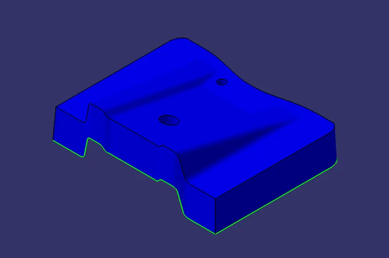
and finally trimmed the class-b with class-c to get the final drafted surface for the component/part.
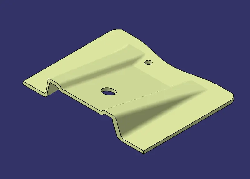
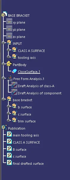
Tree Structure :
solid model with the proper color code of the draft angle :
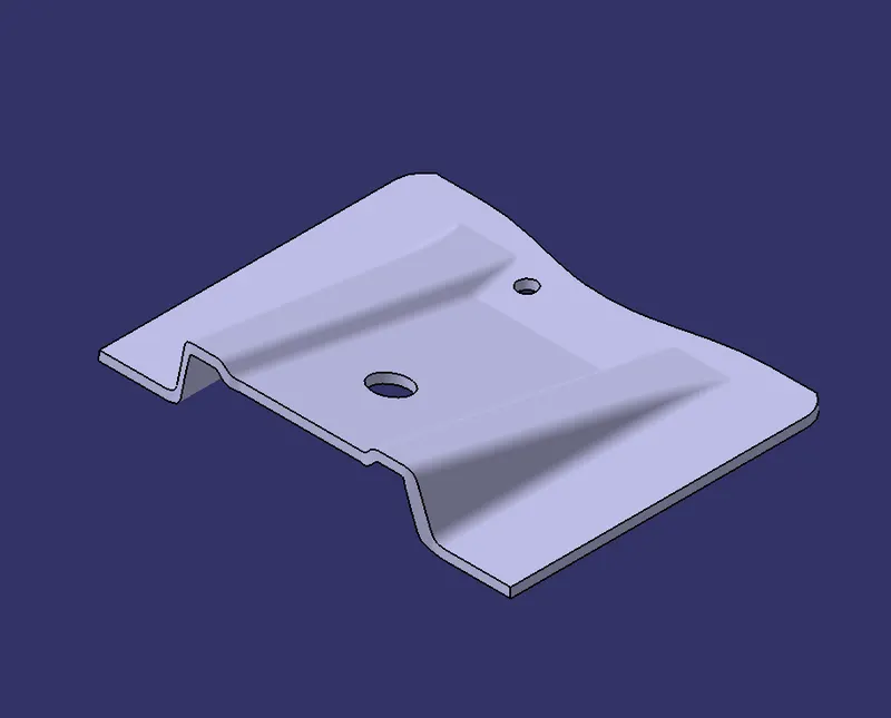
Isometric :
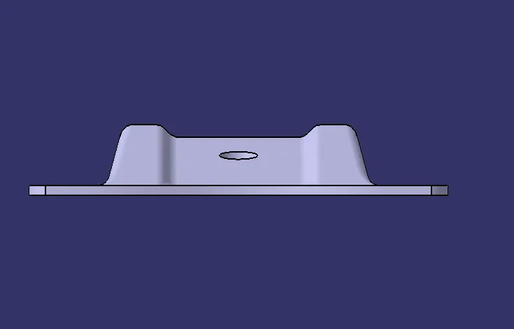
front view :
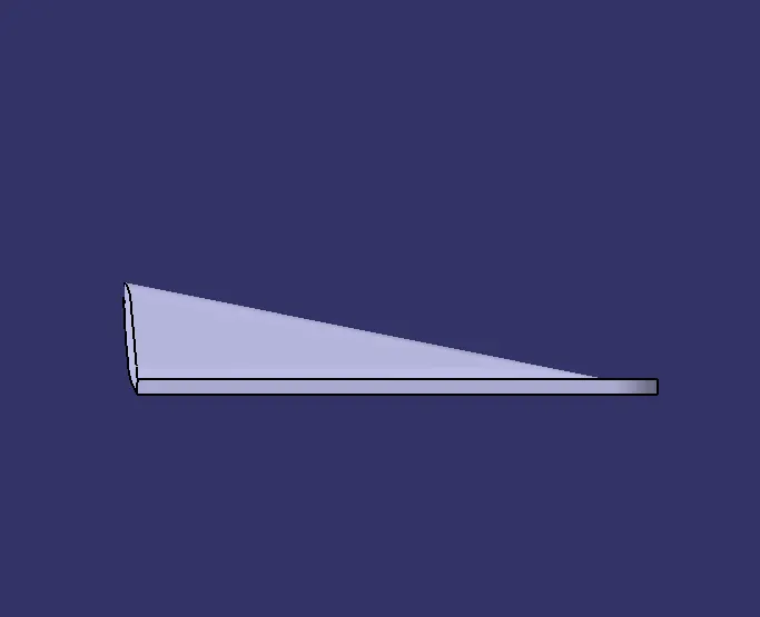
Side view :
Top View :
Base Bracket Plastic component :
isometric view :
front view :
side view :
top view :