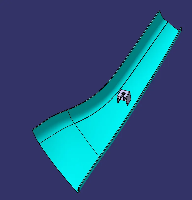
Week 11 - Project - A pillar Design with Master Section
AIM : Creation of a pillar Plastic component of thickness 2.5mm through a given Class-A surface and its engineering features through master section.
REPORT :
WHAT IS TOOLING AXIS : The direction in which the mold or core and cavity opens is the tooling axis.
HOW TO CREATE A TOOLING AXIS :
1) Before creating a tooling axis , as a preventive measure check the Connectivity of Class-A surface. it can be done by using the "join" or "boundary" command. using these command we can identify any unnecessary openings of the class-A surface.
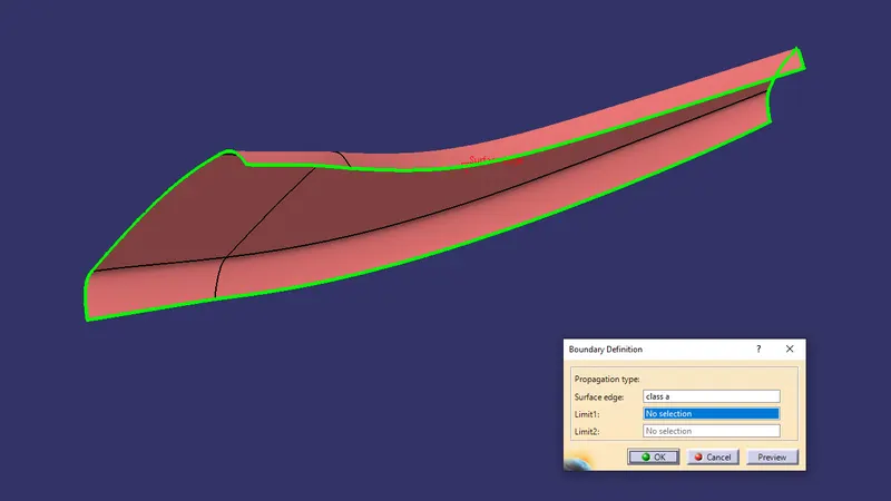
no unnecessary openings are found.
2) visually analyse which is the best possible way to create the tooling axis , considering avoiding side cores, easy ejection of component from core, easy flow of molten plastic inside the cavity.
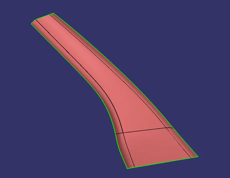
tooling axis along 'x' & 'z' is impossible here , and considering the flat surface in the number plate area , 'y' axis is perfect for tooling axis.
tooling axis creation using Bisecting method :
As per its name , in bisecting method we bisect lines which are along the class a surface walls which we think might create an issue while manufacturing , as the result of the bisection we get a line which clears each and every sub surface of the class a . and we consider the line as tooling axis for the component.
but for this surface there are multiples walls to consider , that is why we are performing along axis method . as we can clearly see along 'y' axis the class a is completely visible , but not along 'x' & 'z' , so we will create tooling axis along 'y' direction.
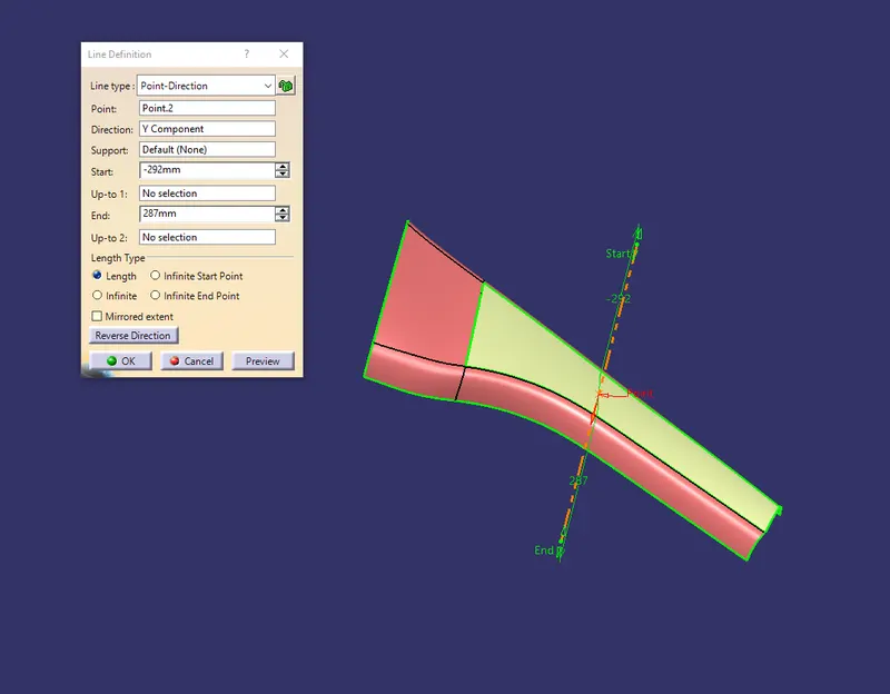
- extracted a flat surface along 'y' axis .
- created a point in the middle of the surface .
- using point-direction command created a line / tooling axis on that point along 'y' direction.
- then to confirm the tooling axis is clearing every surface of the class a or not , performed draft analysis.
side core tooling axis :
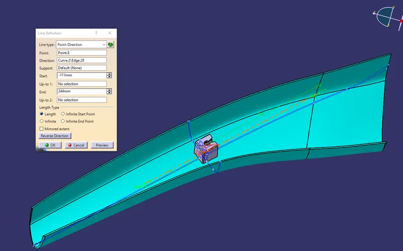
followed the same approach as main tooling axis , but for direction considered the master section.
Draft analysis :
After determining the tooling axis , Draft analysis is done.draft analysis is used to check whether the desired draft angle is maintained or not. Compass is used in the draft analysis command to define the draft direction. as an output of this operation , we will be receving a colored range table , which will clearly show which surface of the component is getting cleared or not with the required draft angle , and with that result we can modify the surface.
Draft analysis for class-A :
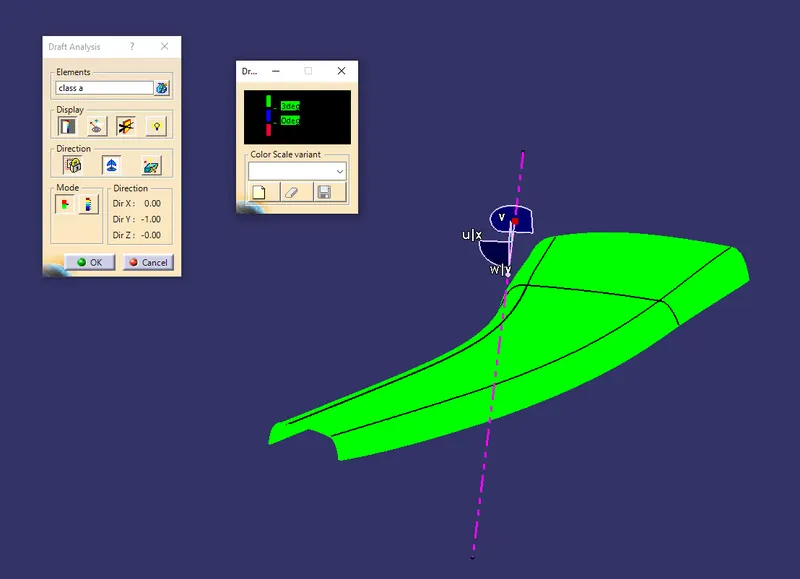
every surface is clearing with 3 degree draft angle .
Draft analysis for a pillar plastic component :
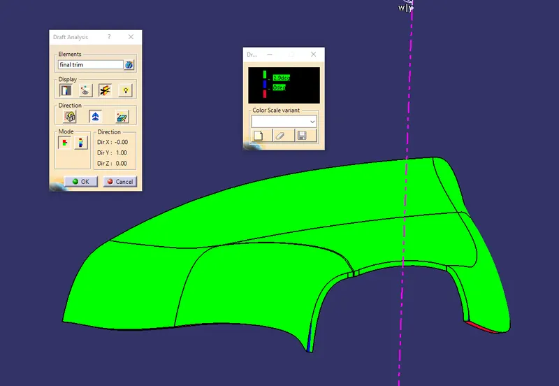
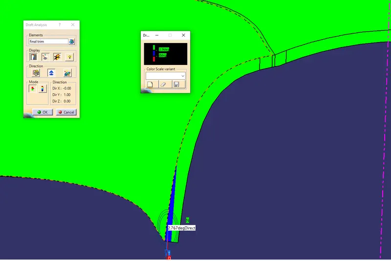
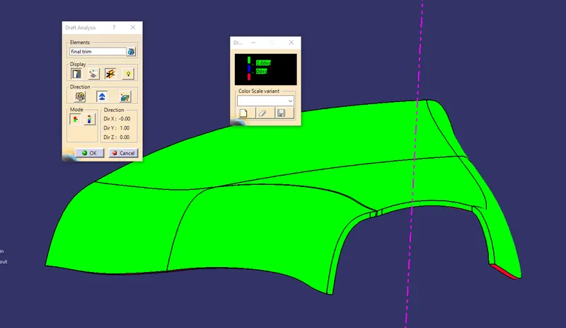
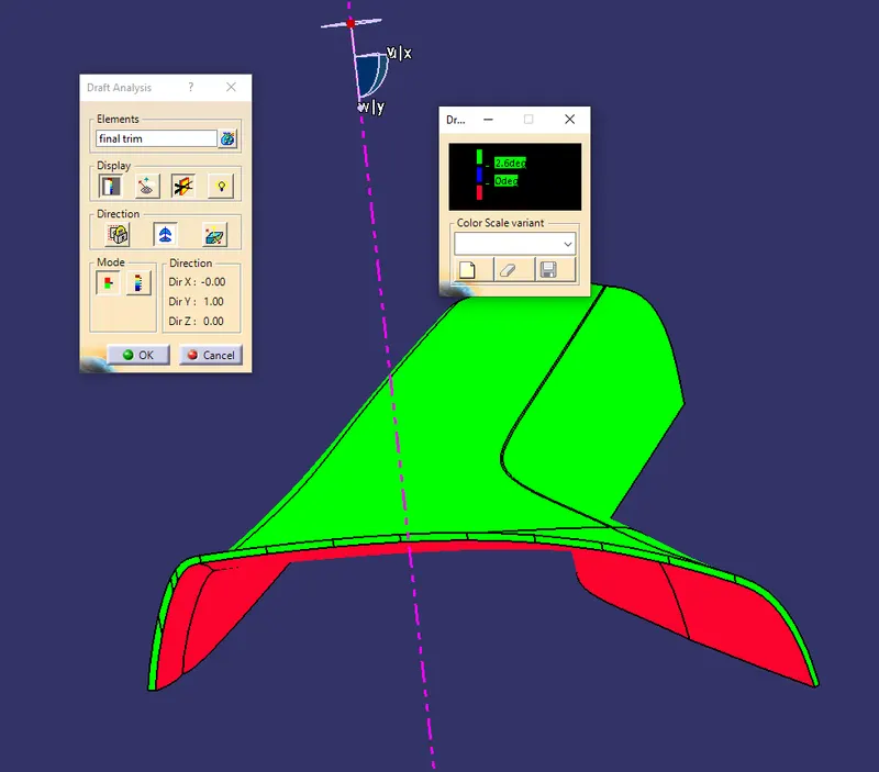
considering 30% +- deviation rule , every surface is clearing with 2.6 degree .
creation of final component from class-A surface :
Created a class-b surface from class-A surface by first offseting the class a with 3mm, as a result got a surface with some unformed fillets and unformed surfaces . using extrapolate and multisection like commands , created a good quality class b or repaired the unformed offset.
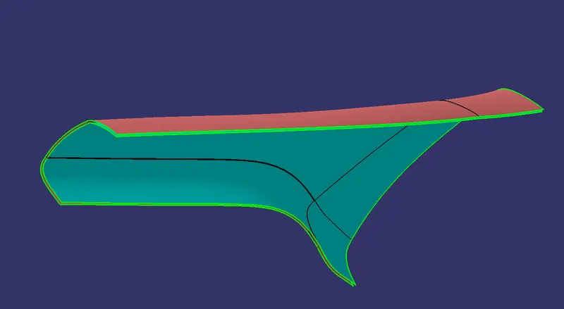
Then created class-c from class-A by first taking the boundaries from class a then sweep them along tooling axis & class-b and then combined the sweeped walls /class c with the class-A surface.
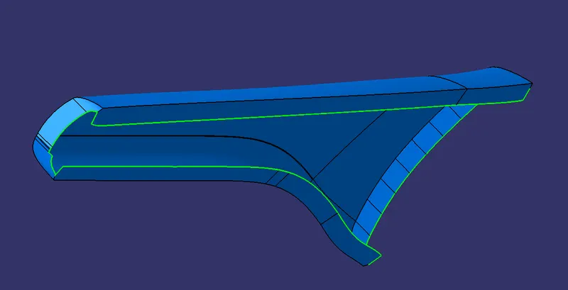
Finally trimmed the extrapolated class-b with class a+c to get the final drafted surface for the component/part.
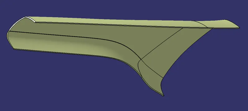
creation of dog house(engineering feature) from master section :
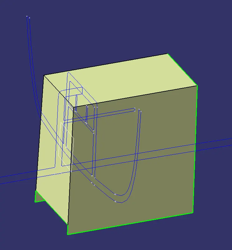
First created a sketch for the dog house outer surface by taking references from the master section.
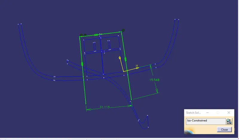
extruded the sketch with the master section width line.
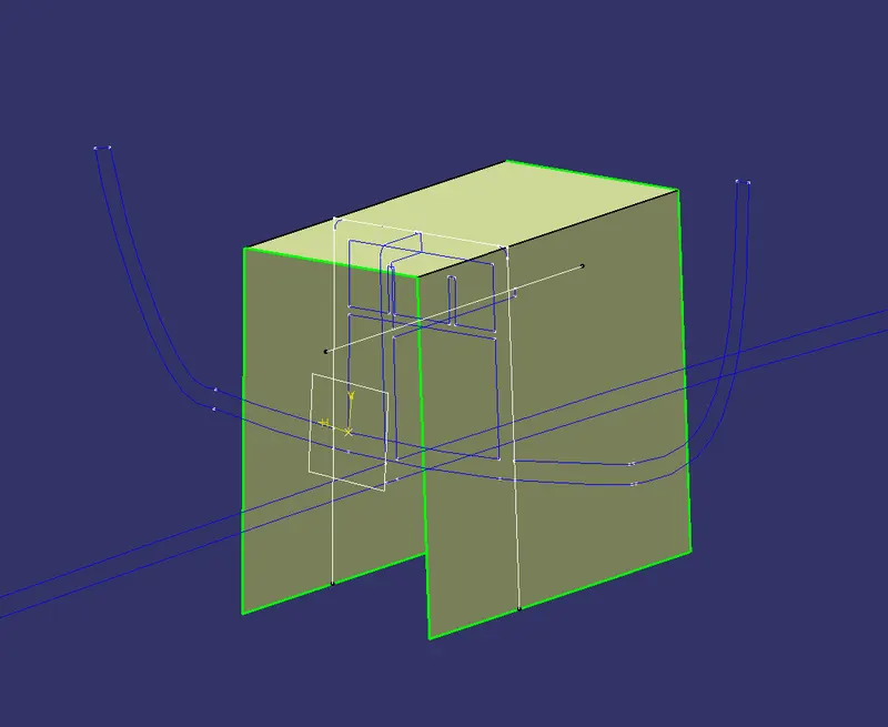
created dog house start and end limt with two lines by taking extract from master section , and then extruded the lines along master section length.
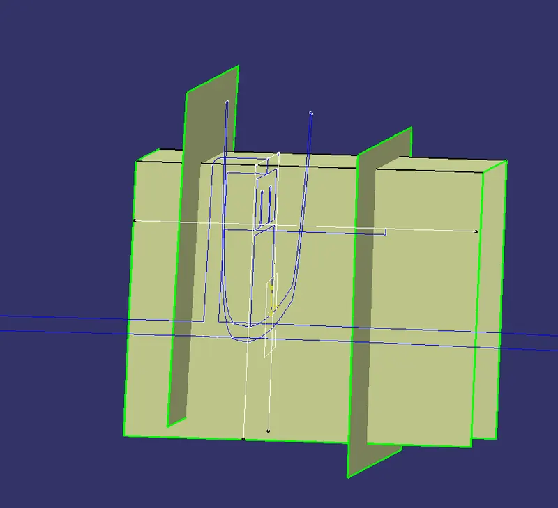
trimmed the end limit extract with the dog house outer surface extract.
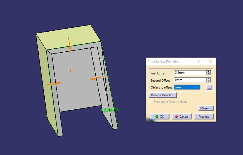
using thick surface command , thickened the trim with 2.5mm thickness .
after that split the body with the start limit extrude , and gave draft to the inside of dog house part , along with edge fillet.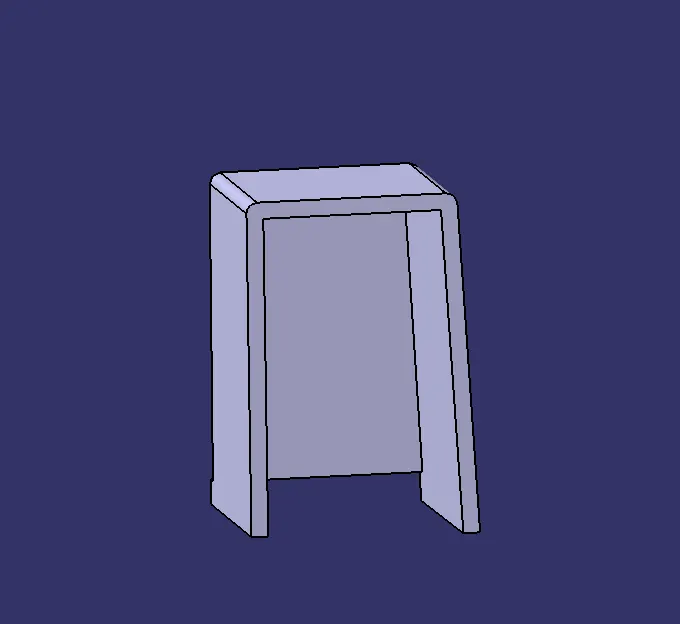
similarly created the ribs and mid part for the dog house insides , by first creating sketch , followed by extrude along master section , then thick surface. then drafted the surfaces with 0.5 degree with the side core tooling axis.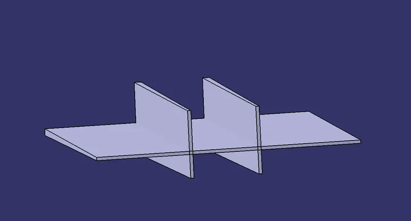
unitrimmed the ribs with mid section. , not gave fillets , because of the smaller dimensions , fillets was cutting the parts a bit.
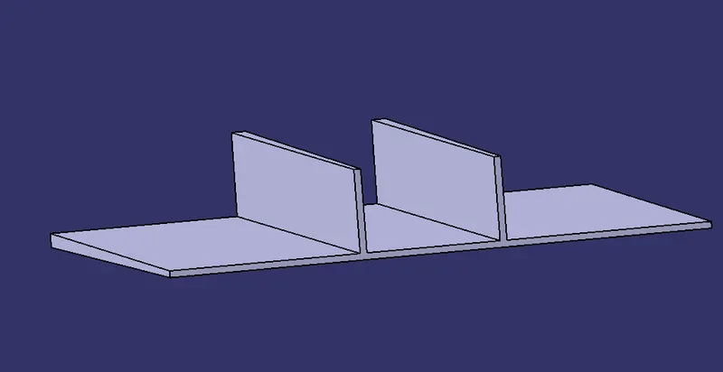
unitrimmed with the dog house part.
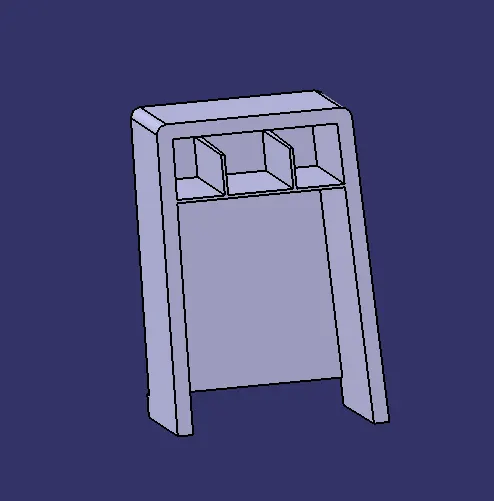
created another sketch for the lower portion of the dog house , and then extruded it with the master surface reference followed by trim with the dog house start and end limits considering 40% thickness rule.
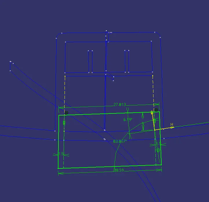
trimmed with the start and end limit of dog house.
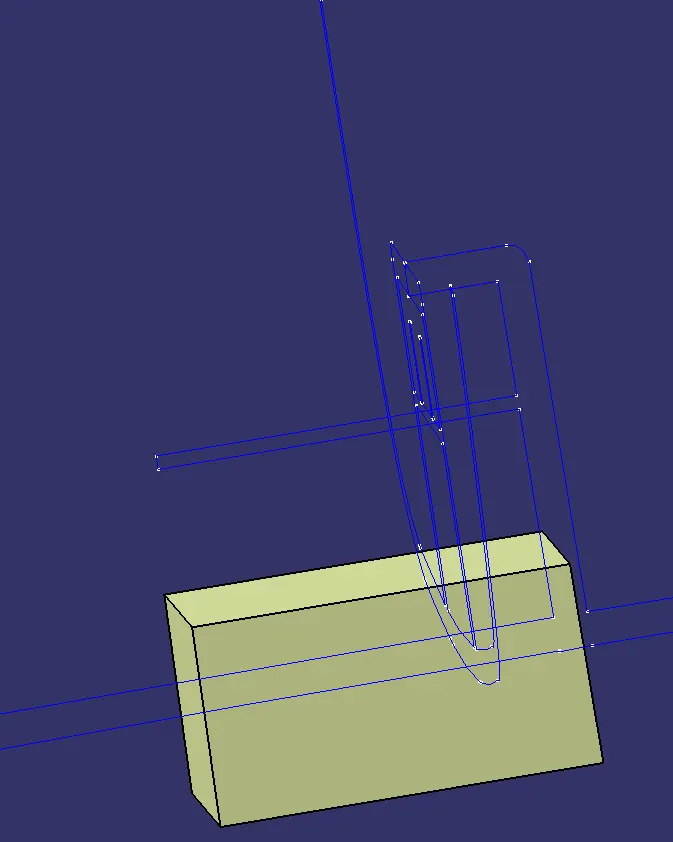
after that using closed surface command , converted the closed surface into a body .and gave it a +ve draft of 0.5 , because this portion will get removed from main dog house body.
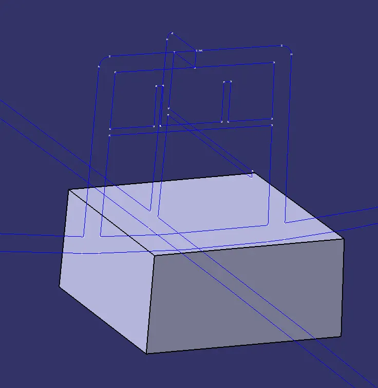
finally removed it from the dog house .
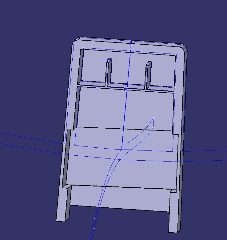
and then splited with the cutout extrude.
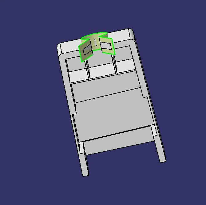
finally unitrimmed the dog house with the a pillar part.
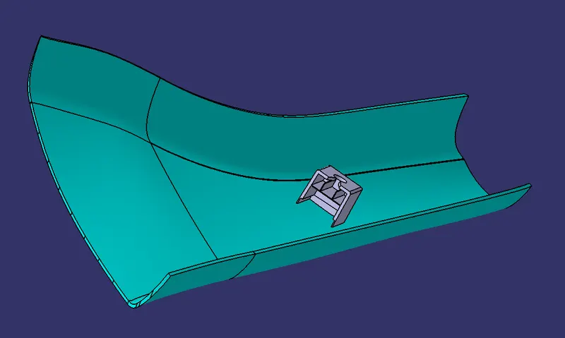
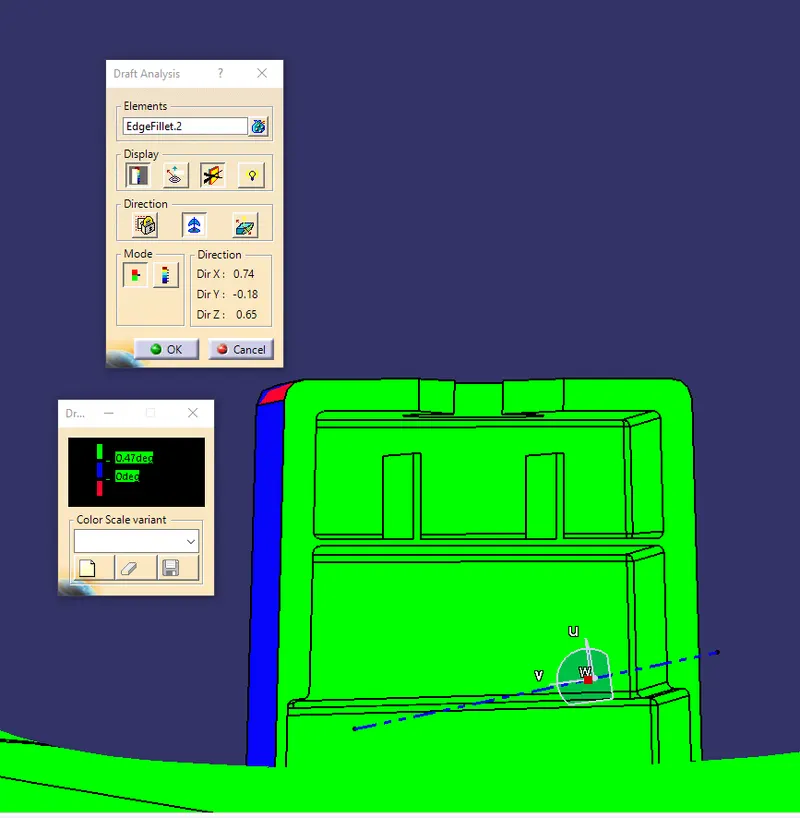
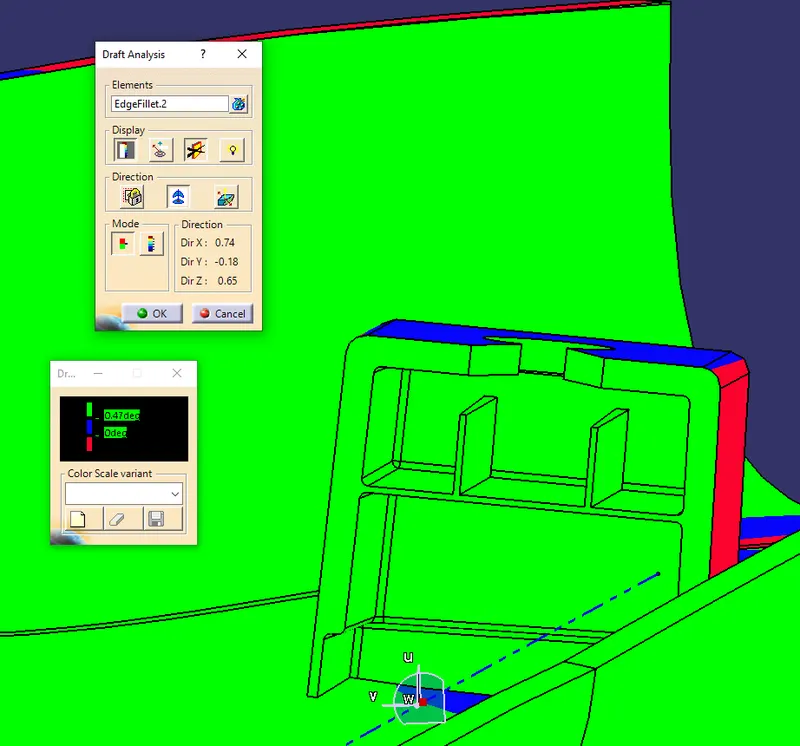
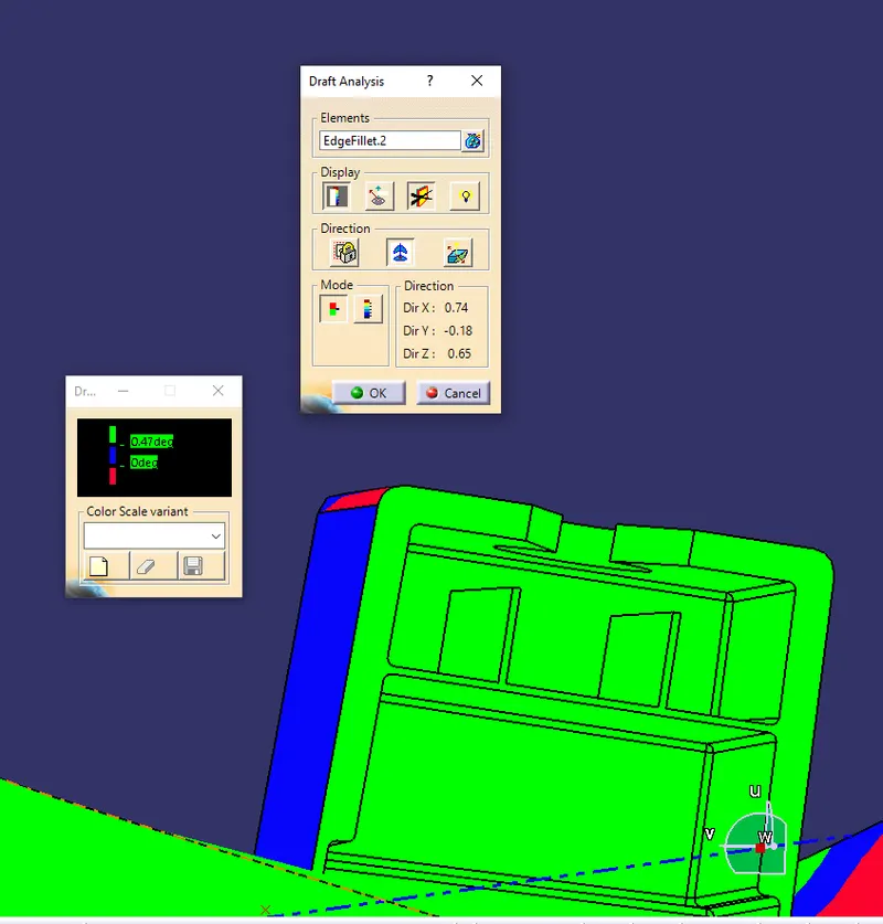
draft analysis for dog house(inside) :
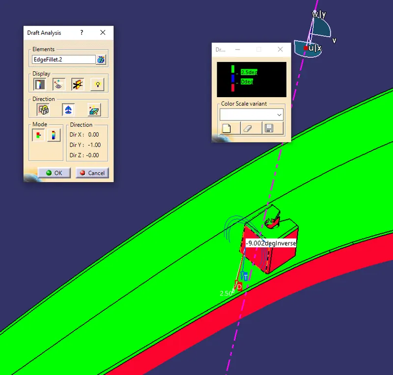
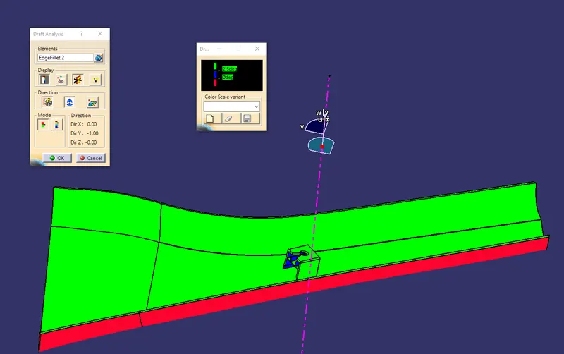
had total control over the draft , gave every surface with .5 degree draft , and every surface is clearing with .47 draft angle.
draft analysis for dog house(outside) :
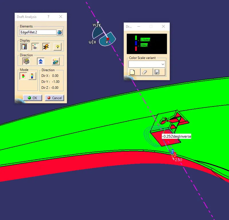
master section is not properly drafted , and i could not change it because the deviation was big.
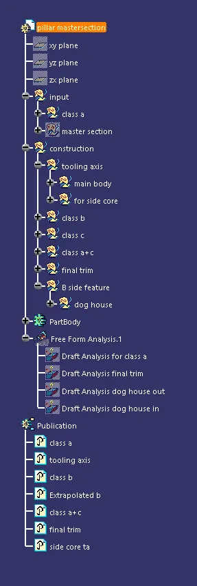
tree structure :
final a pillar part with doghouse :