Week-11 Challenge: Braking
QUESTION 1:
1. For a defined driving cycle, calculate the energy required for braking.
Inorder to calculate the energy required for braking, we must first prepare a user defined drive cycle.
We have a sample drive cycle created from 4 secs to 20 secs and their respective velocities. The drive cycle data is attached below in the form of a spreadsheet.
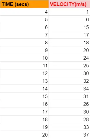
We are asked to calculate the energy required for stopping the vehicle.
First let us understand what braking actually is. Braking is the phenomenon of stopping a moving system by absorbing energy. Energy can neither be created nor destroyed, it can only be converted from one form to another.
In some conventional braking systems, we use a brake pad or a shoe to apply friction to the wheels which in turn converts the kinetic energy of the moving system into heat energy which is then later dissipated into the environment.
Now we have regenerative braking, a simple energy recovery mechanism that makes a moving system stop by converting its kinetic energy in to another form which can be stored for later use.
In today's EV vehicles, we are using regenerative braking system, which does not have any brake pads or shoes, instead the electric motor present will act as a generator, which is the reverse operation of a motor. This stops the vehicle gradually converting kinetic energy into electric energy which can be sent to any battery packs for charging purposes. In this way the parts of the system have longer life since there is no heat energy produced.
In general there is an equation for the energy required for braking. It is :
E = 1/2 * m * V^2.
where,
m - inertia effect of the system or simply considered as the mass of the system. (in Kg)
V - Velocity of the system. (in m/s).
Energy is in joules (J). Now we implement this formula to this user-defined drive cycle data. The screen shot is displayed below.
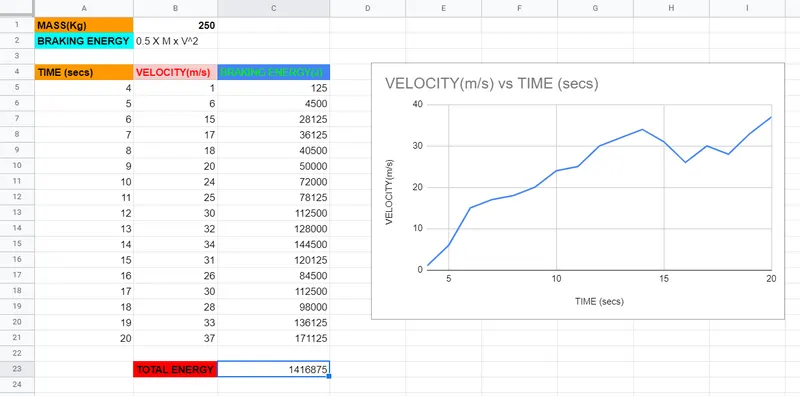
We have applied the formula to each and every velocity input, and we have also calculated the cumulative braking energy of the system as well. We have also plotted the drive cycle as a graph as shown above.
The total braking energy of the drive cycle is 1416.875 KJ
QUESTION 2:
2. Why electric motor can’t develop braking torque at high speed similar to starting?How electric and mechanical brakes are coordinated?
Why electric motor can’t develop braking torque at high speed similar to starting?
The reason why the electric motors can't develop braking torque at higher speeds is:
1). The rate of discharge from the battery is higher than the rate of charging.
According to certain studies, the rate of discharge is twice than that of the rate of charging. To add on the above point, most power converters that we use for motor controls are of the inverter type. We need these power converters to be bi-directional also because during the case of regenerative braking, the motor acts as generator and we need to pass this electric current as DC current back to the battery. So instantaneous braking is impossible.
Moreover the battery SOC, the pressure applied on the vechicle during regeneration is very low, so we can't rely on one brake system alone.
So we have to use a combination of both frictional braking and regenerative braking to stop the vehicle at higher speeds. During lower speeds, regenerative braking alone can stop the vehicle.
Hence, to answer this question, the limitations of power converters and the discharge rate hamper the braking torque of electric motors at higher speeds.
How electric and mechanical brakes are coordinated?
We discussed in the above scenario that both mechanical(friction) braking & regenerative braking is required for higher operating speeds. The control action is co-ordinated in two possible ways or strategies:
1. Series type. (One brake after another).
2. Parallel type. (both at the same instant).
Series type is used for lower speeds only, while the parallel type is used to stop the vehicle instantaneously.
Regenerative is used for a certain time period while the mechanical brake is applied when absolutely necessary.
Some best examples of combined & co-ordinated braking is the NISSAN LEAF model & KIA NIRO hybrid model.
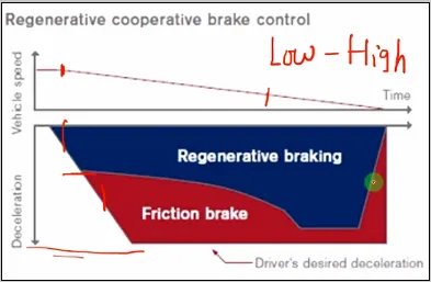
At higher speeds, both regenerative and mechanical is applied, as per the graph above, but when speed slowly decreases, regenrative braking takes over mechanical braking, because it can operate effectively at lower speeds.
QUESTION 3:
3. Make a MATLAB program which plots contour of given motor speed, torque and efficiency values. Attach the code as a .m file attach a screenshot of all the plots.
Let us look at the MATLAB code and go through the step by step explanation.
clear all
close all
clc

% Speed and torque values
speed = linspace(0,1000,300);
torque = linspace(0,700,300);

% Converting speed & torque to 2-D grid
[X,Y] = meshgrid(speed,torque);

% Motor constants
Cl = 0.15;       %Copper losses(Losses due to wire resistance in primary & secondary windings)
Il = 0.002;      %Iron losses(Eddy current loss happening inside the armature)
Wl = 0.0054;     %Windage losses(Losses due to air resisting the rotation of the rotor)
Ml = 17;         %Motor loss constant

% Output power of a motor
OP = X.*Y;

% Total losses in the motor
Loss = ((Y.^2).*Cl) + (Il.*X) + ((X.^3).*Wl) + Ml;

% Input power
IP = OP + Loss;

% Efficiency of a motor
Z = OP./IP;

% Contour plot of efficency with torque and speed
contourf(X,Y,Z)
colorbar
xlabel('speed(RPM)')
ylabel('Torque(N-m)')
title('Contour plot of efficiency')
CODE EXPLANATION:
First we use the default commands clear all, close all & clc to clear the workspace for a fresh start.
Next we use the linspace command to set the range for speed and torque values. The speed value ranges from 0 to 1000 with 300 values & the torque values range from 0 to 700 with 300 values in between.
Then we use the meshgrid command to convert both the speed and torque values as a 2-D grid. With the linspace command, we can only create 1-D values & since we have to plot contours, a 2-D array is necessary.
Then we key in the motor losses happening in the rotor and stator. Those four losses are:
1. Copper losses - Losses happening in the primary and secondary windings in a stator which contains copper wires for conducting current.
2. Iron losses - The armature conductor contains permanent magnets that are made up of iron. Those magnets experience eddy current losses and hysterisis losses.
3. Windage losses - The air flow that opposes the rotor rotation.
4. Motor constant losses.
Now the input power, output power & efficiency formulae are inserted. Use the element wise operator (dot operator) wherever necessary.
The formulae efficiency e = Output power/Input power.
Output power is the mechanical energy of the motor and it is the product of speed and torque.
The input power is the electrical power and it is the combination of mechanical energy and the electrical losses happening in the motor.
Use the command contourf to create a contour plot and label the x-axis & y-axis using the xlabel and ylabel command. Use the colorbar command to create a legend for the values of efficiency within the plot.
The contour plot will look like this:
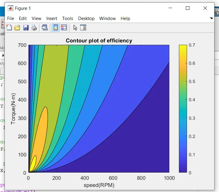
We can see from the plot that for lower values of torque and speed, the efficiency is higher. As the values of torque and speed increase, the efficiency decreases.
This is evident from the contour that for starting values of speed and torque (0 to 100), the efficiency is highest (0.7).
This is the inference from this MATLAB program.