Project 1 (Mini Project on Vehicle Direction Detection
We are asked to develop a model for the Vehicle Direction Detection feature in MATLAB. Let us look at the requirement and analyze what is needed to develop this feature.
General Overview:
Identifying the direction of the vehicle is one of the important & diverse features in Autonomous driving & Advanced Driver Assistance Features. This particular sub-feature of identifying the direction of vehicle is basically identifying the direction the vehicle is taking based on the camera input.
Camera reads the road signs & stores into its memory with unique values for left turn, right turn & straight drive. Depending on the direction it is taking, final indication is given to the driver – as an indication if he is driving in the recommended direction or not.
Vehicle Direction Determination can also be coupled along - side features like GPS systems to identify whether the vehicle is reaching its destination in an optimized manner. This sub feature can also be used along with Lane Detection, Highway Warning, Ramp Entry / Exit in Wrong Way Detection etc.
This is the application of Vehicle Direction Detection feature.
The expected outcome of this project is to:
- Develop the MATLAB-Simulink model as per requirement.
- Tag the requirements to the simulink model; tagging requirement 1 & requirement 2 to their corresponding subsystems is fine.
- MBD compliant changes, Data Dictionary creation & code generation is added advantage, and that is not scope of this project.
- If choosing code generation, Storage class for Input signals: ImportedExtern; Storage class for Output signal: Export to File; Storage class for local signals: localizable; Storage class for calibration signals: Const.
- Choose sample time for all signals as 0.01s.
We will follow these protocols mentioned above to complete this project.
Since our software is not compatible with embedded coder, we may not be able to generate the code out of this model. But we will create the model, simulate it & check it's functionality.
We are given two requirement documents. They both have to be modelled as a seperate subsystem.
Let us first look at requirement-1 and develop the subsystem accordingly.
The first requirement is about defining the different steering wheel input positions & creating a logic for them. After creating the logic, the vehicle's position status must be determined.
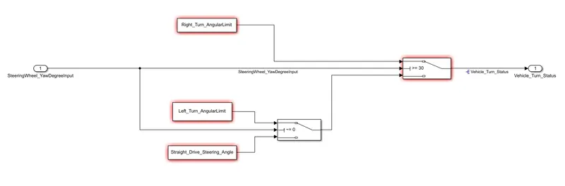
Requirement - 1:
- Steering wheel input as yaw rate (Signal name: SteeringWheel_YawDegreeInput) is the input for this system. The yaw rate is nothing but the rate of rotation of the steering wheel(Front wheels) & it's unit is in degrees. Based on the rotation of those front wheels, we can decide in which direction the vehicle moves.
- Use the inport block to create the yaw rate input and name it accordingly with the signal name.
- This is compared against 3 angular values, one each for left turn, right turn & straight drive (Calibration Values: Right_Turn_AngularLimit, Left_Turn_AngularLimit, Straight_Drive_Steering_Angle) to say which specific direction the steering wheel is turning towards.
- Since these are calibration values, use the Constant block and under the Constant value, name them as Right_Turn_AngularLimit, Left_Turn_AngularLimit, Straight_Drive_Steering_Angle given above. Later, we can use the data dictionary to define these calibration parameters.
- In total, there should be three constant blocks.
- Use switch blocks to compare & develop this requirement. Keep this requirement in a subsystem & output of this requirement is a local signal (Signal Name: Vehicle_Turn_Status).
- Use two switch blocks, one to compare the input with the right turn limit & and the other switch block to compare with left turn limit and straight drive limit. Based on the yaw rate input, these switches compare and updates the vehicle's direction.
- Use the outport block for the output signal(Signal Name: Vehicle_Turn_Status). Name it according to the output signal name. After finishing the requirement, create the entire requirement as a subsystem.
Now we will look at the requirement subsystem 2.
The second requirement is whether the steering wheel position matches with the camera input. This is done to ultimately find out if the vehicle is moving along the desired direction.
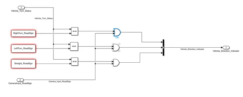
Requirement – 2:
- Keep this requirement as a separate subsystem. Inputs to this requirement are local signal from requirement 1 (Signal Name: Vehicle_Turn_Status) & an input signal from camera (Signal Name: CameraInput_RoadSign), which confirms the occurrence of a road sign.
- Use the inport blocks and name them accordingly just like requirement 1.
- Signal Vehicle_Turn_Status is compared against calibration values (Calibration Values: RightTurn_RoadSign, LeftTurn_RoadSign, Straight_RoadSign). Use the constant blocks and calibrate them as RightTurn_RoadSign, LeftTurn_RoadSign, Straight_RoadSign using the constant value dialog box. We will define these calibration parameters using the data dictionary later.
- If each of them is found equal, then each of the three corresponding output is compared against the camera input signal. To compare if they are equal, use the relational operator blocks. Use the equal to (==) sign.
- Using a logical operator block, only one among them is finally given as output signal (Signal Name: Vehicle_Direction_Indicator).
- The most suitable logical operator to be used in this case is the OR operator. The OR operator compares two inputs and returns a boolean value 1, if any one of the input is 1.
- Finally, use the bus creator block to create a single bus signal, which contains all the three output signals.
- Use the outport block for the output and name it as Vehicle_Direction_Indicator. Now that we have completed the requirement, create it as a subsystem.
After creating the requirements as subsystems, the model will look like this.

Name all the input & output signals in the simulink environment so that we can specify them in the data dictionary.
For better presentation purposes, we will create another subsytem and include the requirements in it.
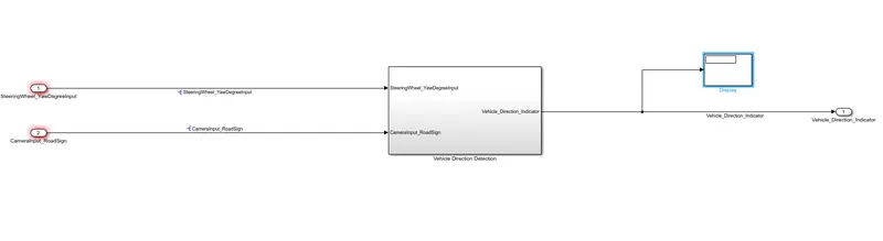
Add a display block to the output signal to display the output.
Now our model is developed completely. The next step is to create a simulink data dictionary.
We already have the list of signals and parameters to be added into the data dictionary.
There are 4 signals and 6 parameters in total :
3 input signals : Vehicle_Turn_Status, CameraInput_RoadSign, SteeringWheel_YawDegreeInput
Output signal : Vehicle_Direction_Indicator
Calibration parameters :
Right_Turn_AngularLimit, Left_Turn_AngularLimit, Straight_Drive_Steering_Angle, RightTurn_RoadSign, LeftTurn_RoadSign, Straight_RoadSign.
Use the model properties to create a data dictionary file and add these information in it.
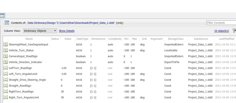
Please note that the signal and calibration names must match exactly with that of the block and port names. Otherwise MATLAB will throw errors.
Now link the data dictionary with the model. Now, the model is ready for simulation.
We will change the values of the input (SteeringWheel_YawDegreeInput) & check the display block for results.
Input 1:
When the yaw rate is at 0 degrees. (Steering wheel angle at 0 deg)
To specify the value of the signal, go to the data dictionary and click on the SteeringWheel_YawDegreeInput signal. Enter the value under the initial value dialog box. Repeat the same procedure for different input values.
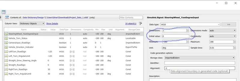

The output is 0 0 1, which means that the vehicle is moving in a linear manner. The output is correct.
Input2:
When the yaw rate is 30 degrees. (Steering wheel angle at 30 deg)
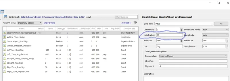
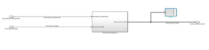
The output is 1 0 0, which indicates that the vehicle is taking a right turn. The output is correct.
Input3:
When the yaw rate is at -120 degree. (Steering wheel angle at -120 degree)
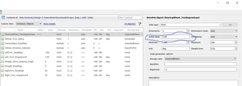

The output is 0 1 0, which indicates that the vehicle is taking a left turn. The output is correct.
Thus, the functionality of the model is perfect. This model can be used for code generation.
The final step would be the requirements tagging & traceability. This is done to check whether the modeling is done as per the requirement document.
Convert the requirement into a word document. Now right click on the requirement subsystem and select requirements - open outgoing links dialog. A dialog box opens.
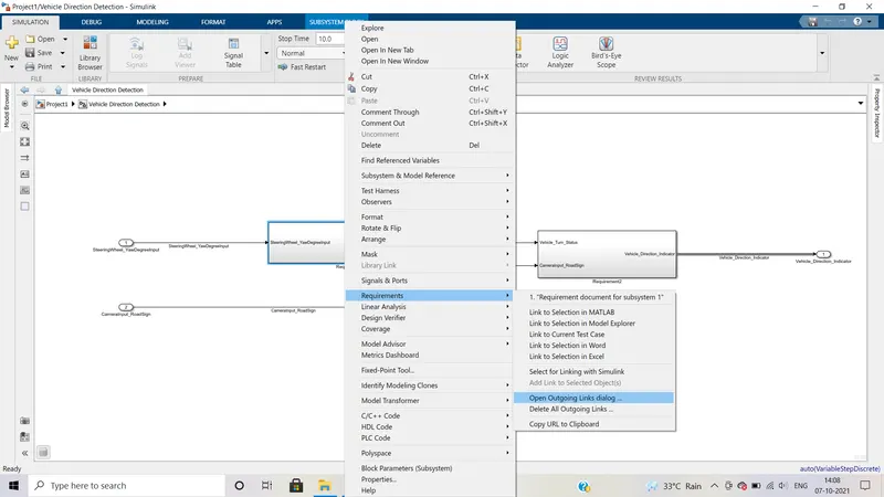
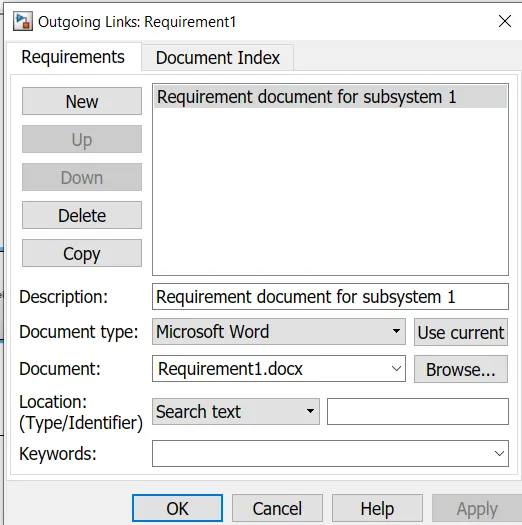
Browse and add the word document. Now whenever you click on the subsystem and select requirements, a word document will be tagged. This can be used for reference.
Thus, the entire MBD process is followed inorder to develop the Vehicle Direction Detection feature.
The code generation process could not be completed because this version of MATLAB does not support the embedded coder.