Project 2
AIM:
1. To model the given model (Rear suspension assembly) and to give appropriate connections throughout the model.
PROCEDURE:
a). PERFORMING THE TOPOLOGY AND GEOMETRY CLEAN-UP:
1. The given model is the rear suspension assembly fitted along with the vehicle tyre and rim. While importing the model to the ANSA software, the model looks like this.
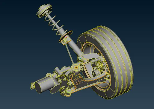
2. Perform the complete topology using FACES-TOPO option. Also refine the model to a length of 1mm using PERIMETERS-LENGTH option to view the quality of the CAD model.
3. Run the CHECKS manager for any geometrical errors. There will be certain geometrical errors such as triple cons, unchecked faces and single cons. Adding or deleting new faces will remove such errors. Use the FACES-NEW option to add faces. You can also use the AUTOFIX option in the CHECKS manager to correct such errors.
4. Now that we have cleaned up the model, we can proceed to 2-D and 3-D meshing.
IDENTIFYING THE COMPONENTS FOR MID-SURFACE EXTRACTION AND MESHING:
1. This is a model consisting of various parts with different thickness values. In general, we can extract the mid-surface for components that has a thickness of 5mm or below 5mm. In this model, there are only few components that has a thickness of below 5mm. Those surfaces are shown below.
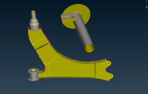
These are the only components that fall under a thickness value of 5mm. These components can be mid-surfaced using the FACES-OFFSET option. Store them under seperate PID's and specify their thickness.
2. The 2-D meshing components have a seperate quality criteria. The values are attached below.
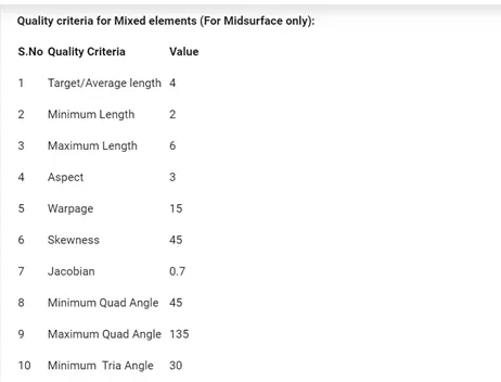
Use these criteria for meshing these surfaces.
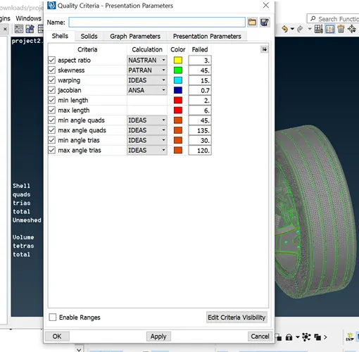
3. Refine the target element length to a value of 4mm. Then enter these values in the quality criteria as shown below.
4. Mesh the component and remove off elements, opposite trias, back to back trias and rotating quads. Use the RECONSTRUCT, RESHAPE and SMOOTH options to achieve a better mesh flow.
5. After meshing, our surfaces will look like this.
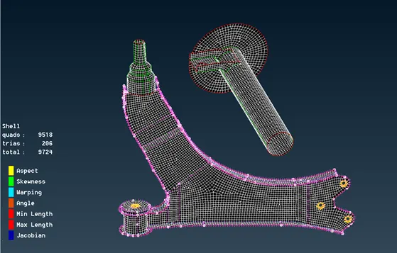
Now let us look at the areas that require 3-D meshing.
MESHING OF RIM AND TYRE:
1. It is already given to us that the rim and tyre should be approached as a solid mesh component. And the quality criteria is also given to us seperately. Store the rim and tyre in seperate PID's to isolate them from the suspension assembly.
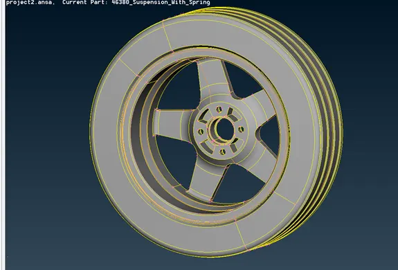
This is how the rim and tyre looks like. We have to capture them with ortho tria and tria elements.
2. The seperate quality criteria for the tyre and rim is attached.
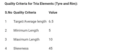
3. In the MESH PARAMETERS menu, enter these quality criteria values and in the elements dialog box choose either ortho tria or tria elements.
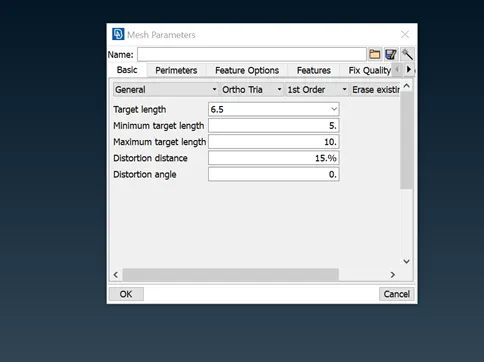
4. Now proceed to mesh the component. Use the SPOT MESH option in the MESH GENERATION menu to get a good tria mesh flow. Use ortho tria elements in fillet and curved macros and use normal tria elements in flat surfaces.
5. After meshing and clearing off elements, our model appears as below.
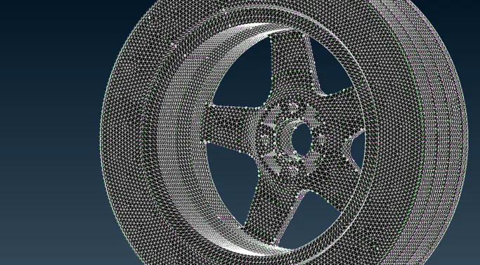
6. Now we have to generate the volumes for the rim and tyre. In the V.MESH module, use the DEFINE-MANUAL option to define the entity first. Then after creating the volume mesh, use either the TETRA RAPID or TETRA FEM method to mesh the inner volume.
7. The quality criteria for volume is the collapse and it is 0.2. View the tetra elements formed inside the model by hiding the surface.
3-D MESHING OF SUSPENSION PARTS:
1. Almost 90% of the parts in the suspension assembly are to be 3-D meshed. Since they contain so many macros, seperate them into different PID's and then start the volume mesh.
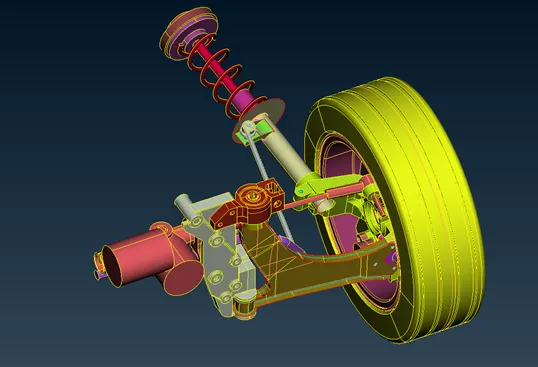
This is the PID visualization of the suspension assembly. Make sure that all our entities are closed and there are no single cons present.
2. Now the quality criteria for the suspension parts are different and they are specified below.
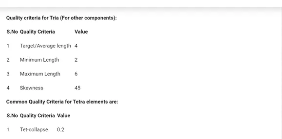
3. Now follow the same method of meshing like we did for the rim and tyre. Go to each and every property ID and capture it with a mixture of ortho tria and tria elements. After meshing them, define a volume and remesh it using TETRA RAPID or TETRA FEM.
4. After meshing and applying volumes our model will look like this.
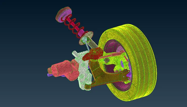
5. Clear the off elements in both the 2-D and 3-D mesh. Also make sure that there are no kinks or sharp edges originating in areas where we created the volume mesh.
6. Now we can proceed to connections.
CONNECTIONS TO BE GIVEN:
1. The areas where the 2-D and 3-D surfaces meet must be connected properly in this model. Some types of connections used in the model are seam weld, 2-noded RBE2 connections, cbar connections, and cluster RBE2 connections.
a). SEAM WELD CONNECTION:
1. Consider the area below.
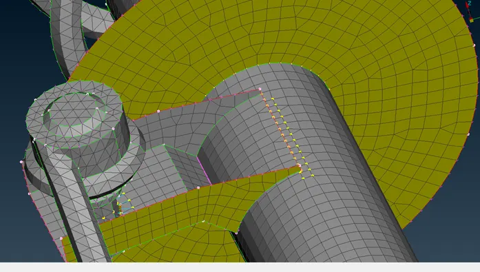
This plate needs to be welded to the cylinder below. This can be done by a seam weld connection.
2. Use the CONS2CURVE option to create a curve and convert that curve into a seam line. After that go to the CONNECTIONS manager and specify the P1 and P2. Enter the search distance, the step length and the width for the weld. After entering all these values, realize the connection. Now there will be a shell overlap connection realised like this.
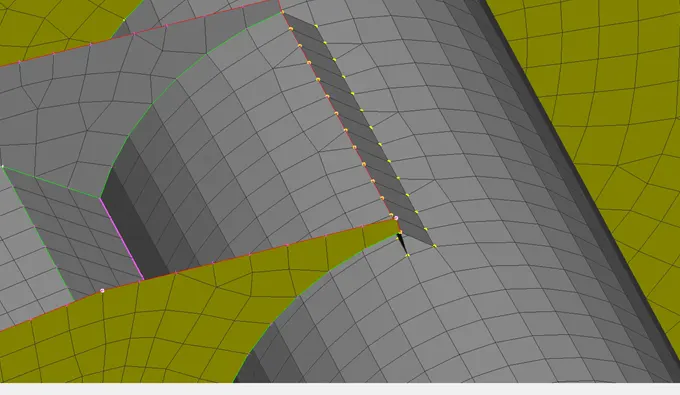
Now the seam weld connection is realised.
b). 2-NODED RBE2 CONNECTION:
1. Consider the volumetric cylinder and the plate below.
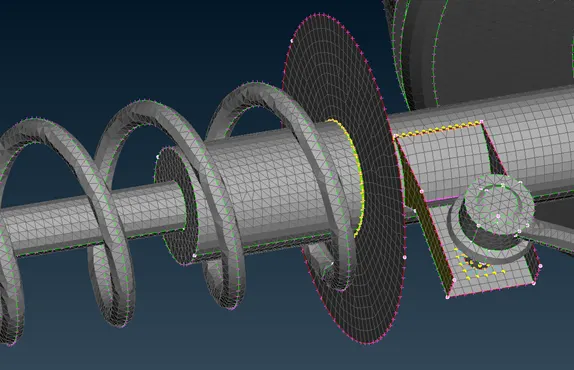
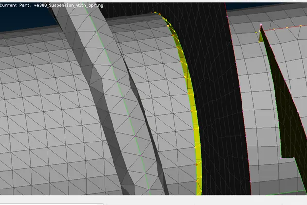
2. The cylinder has been 3-D meshed while the plate is 2-D meshed. A 2-noded RBE2 connection must be done between the nodes of the cylinder and the plate. Project the hot points of the cylinder to the plate. After projecting, enter the NASTRAN deck and select RBE2-TWO NODES. Select the nodes one by one and create the connection.
3. The connection must be established like this.
c). CBAR CONNECTION:
1. We have a spring in the suspension assembly of thickness 10mm. Below is the picture of the spring.
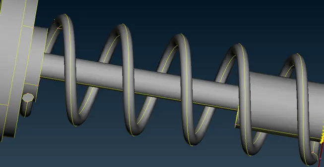
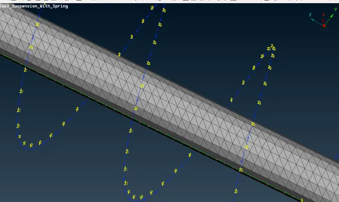
2. We have to model it as a CBAR connection. First, mesh the spring with tria elements. After meshing, create a middle curve for the spring. Then go to the NASTRAN deck and select CBAR-CURVE(seq.). Enter the element length and the radius of the spring and create a property ID. After doing so our CBAR connection will look like this.
d). CLUSTER RBE2 CONNECTIONS:
1. In certain bolt areas or mating parts, we have to create a cluster connection using RBE2-MANY NODES. Those areas are shown below.
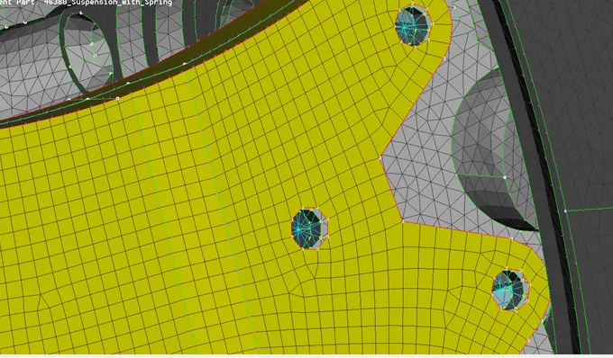
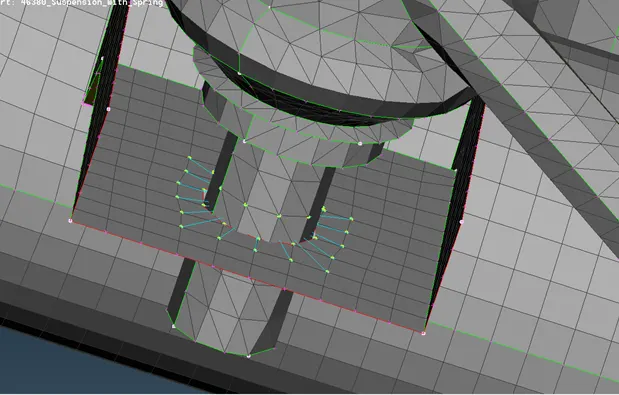
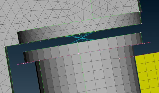
2. In such areas we have to create RBE2 cluster, many nodes RBE2 and connect the master nodes of those connections with a 2-noded RBE2. Use the RBE2 option in the NASTRAN deck to realize these connections.
e). BOLT CONNECTIONS AT THE RIM PART:
1. At the center of the rim there are holes present for the fastening of bolts. A photo is attached below.
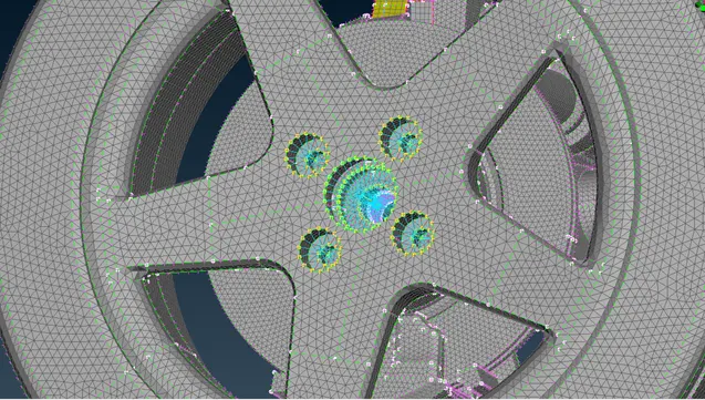
2. This area has to be captured as a bolt and stem representation. In the NASTRAN deck, use the RBE2-MANY NODES, to create a rigid bolt connection. And then to create a stem use the RBE2-TWO NODES, and select the master nodes of the created RBE2 elements to make a stem in between.
These are the different types of connections used.
LEARNING OUTCOMES AND CONCLUSION:
1. Through this project, we learnt about identifying the areas that require 2-D meshing approach and 3-D meshing approach.
2. We also learnt on how to connect a complex sub-system like a rear-suspension system.
3. We learnt on how to seperate systems into individual components.