Week -2
AIM:
1. To construct a doorbell simulator using the SOLENOID block in SIMULINK. Create a situation where the switch is closed for 2 seconds and then released.
2. To also construct a thermistor to sense the temperature of a heater & turn on or turn off the fan as per below conditions:
Temperature source: 20 °C from 0 to 10 seconds, 27 °C from 10 to 30 seconds, 23 °C from 30 to 50 seconds
Fan conditions: ON if the temperature above 25 °C, OFF otherwise.
INTRODUCTION:
1. Let us look at the working of a solenoid and understand it completely before proceeding to simulation.
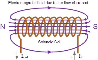
A solenoid is a device comprised of a coil of wire, the housing and a moveable plunger (armature). When an electrical current is introduced, a magnetic field forms around the coil which draws the plunger in. More simply, a solenoid converts electrical energy into mechanical work.
The block that we use in simulink looks a lot more like this.
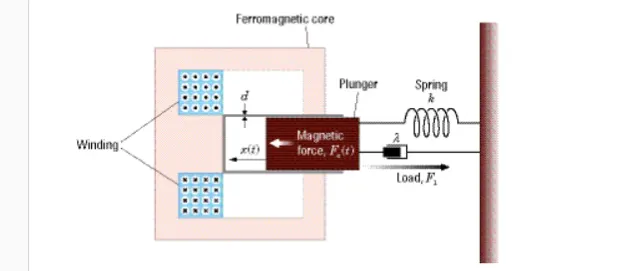
The magnetic field created by the solenoid pushes the plunger towards the bell which makes a sound whenever current is passed through it. This is the main concept involved in the working of a doorbell.
PROCEDURE:
DOORBELL SIMULATOR:
1. Create a BLANK MODEL in SIMULINK to start adding blocks and create connections.
2. The doorbell simulator circuit is attached below.
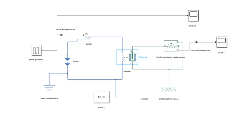
3. Let us look at the blocks that are involved in creating the circuit:
a). PULSE GENERATOR- Pulse generators are electronic test equipments used to create periodic rectangular pulses. This comes in handy as we have to close the circuit for every 2 secs.
b). SIMULINK-PS CONVERTER- The input given in the pulse generator will not be in a readable form. So we need a converter which converts constant inputs into physical signals.
c). SWITCH- Switches are used to engage and disengage electrical circuits.
d). BATTERY- Used as a power source. We need a power source to pass current through the solenoid.
e). ELECTRICAL REFERENCE- Ever electrical circuit must contain an electrical reference (electrical ground). Connect this block anywhere within the electrical circuit.
f). SOLENOID- This model is based on the principle of solenoids, hence the solenoid block. The ports R & C denote the plunger positions. This block is arranged in such a way that the plunger moves from port R to port C.
g). IDEAL MOTION TRANSLATIONAL SENSOR- This block is used to measure displacement and velocity in a mechanical network. The translational motion of the plunger is recorded by this block. This block will have 4ports, R, C, V & P. The physical signal ports V and P report the displacement and velocity, respectively, of port R relative to port C. The measurement is positive when the motion at R is greater than the motion at C.
h). MECHANICAL REFERENCE- In order to record translational motion, we need a reference point. This is given by the mechanical reference block. Connect the block to the port C of the IDEAL MOTION TRANSLATIONAL SENSOR block to record the displacement and velocity.
i). PS-SIMULINK CONVERTER- This is used to convert physical signals from the IDEAL MOTION TRANSLATIONAL SENSOR block into readable inputs.
j). SCOPE- Used to plot for all values of stop time and its corresponding resultant values.
k). SOLVER CONFIGURATION- This defines the solver inputs for the simulation. Every physical system must have atleast one solver block. Connect this block anywhere within the system.
WORKING:
1. As soon as we add the pulse generator block, we need to set the input values. On double clicking the block, we see a dialog box as below:
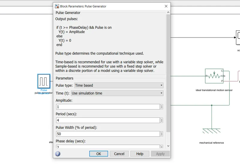
2. Since our condition is to engage for every two seconds, our input values will be:
PULSE WIDTH- 2, PERIOD-4, PHASE DELAY-2.
3. Double click on the SCOPE1 block to see how the pulses are generated. The plot will look like this:
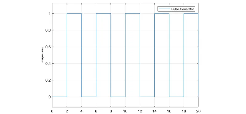
The Y-axis denotes amplitude which was set to 1, and the X-axis which denotes the time period.
4. Make the connections as per the circuit diagram posted above. Run for a stop time of 20 secs, and view the result by double clicking on the SCOPE2 block. This plot displays the plunger position at various points of time.
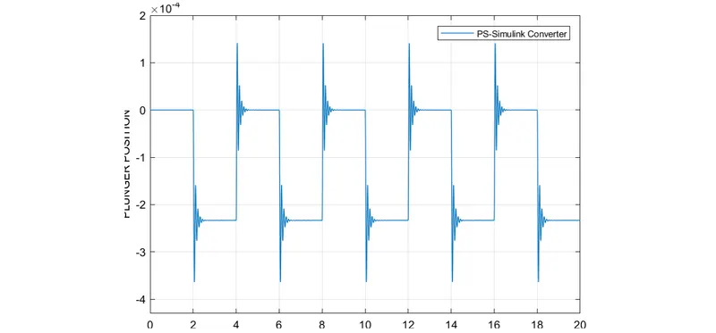
This is how we can simulate the doorbell model.
THERMISTOR MODEL:
1. Similarly let us look at the working of a thermistor before proceeding to simulation.
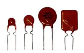
Thermistors are thermally sensitive resistors whose prime function is to exhibit a large, predictable and precise change in electrical resistance when subjected to a corresponding change in temperature. There are two types of thermistors:
a). NTC Thermistor- With an NTC thermistor, as the temperature increases the resistance decreases, and when the temperature decreases, the resistance increases.
b). PTC Thermistor- With a PTC thermistor; the temperature will increase and decrease with the resistance.
We use the NTC thermistor in this model. Now let us look at the circuit and the various blocks used.
Our aim is to use a thermistor to sense the temperature of a heater & turn on or turn off the fan as per below conditions:
Temperature source: 20 °C from 0 to 10 seconds, 27 °C from 10 to 30 seconds, 23 °C from 30 to 50 seconds
Fan conditions: ON if the temperature above 25 °C, OFF otherwise
PROCEDURE:
1. As usual, create a BLANK MODEL and start importing the blocks into the model.
BLOCKS USED:
1. The circuit diagram is given below:
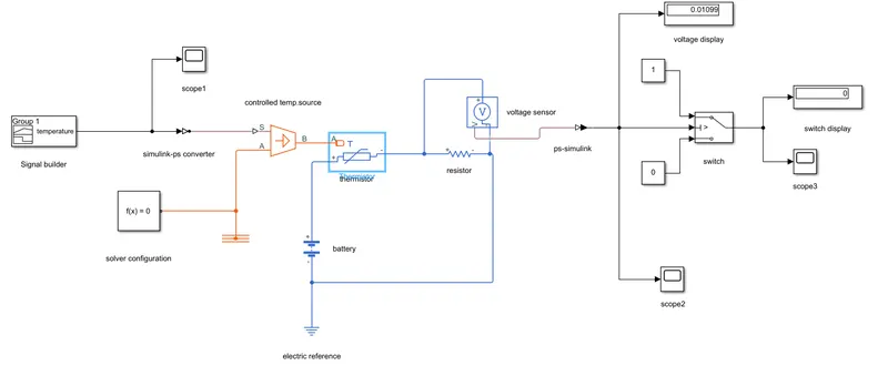
SIGNAL BUILDER- A signal builder is used to provide variable inputs (inputs that change as time changes). Here our input temperature must be at 293k for first 10 secs, 300k for the next 20 secs and 296k for the last 20 secs.
SIMULINK-PS CONVERTER- The input given in the signal builder will not be in a readable form. So we need a converter which converts constant inputs into physical signals.
CONTROLLED TEMPERATURE SOURCE- This will keep the temperature flow constant regardless of the variable input. This block contains three ports S, A & B. The S port will be the physical input port the comes from the converter block.
THERMAL REFERENCE- This block represents the reference point in a thermal network where the temperature is zero. Connect the reference block to the A port of the controlled temperature source.
THERMISTOR- Connect the output port B to the A port of ther thermistor block. The thermistor will have positive and negative terminals which will be connected to a battery.
BATTERY- Used as a power source.
RESISTOR- Used to resist current flowing through the circuit. Connect the resistor along with the thermistor as shown above in the circuit.
VOLTAGE SENSOR- Used to measure the potential difference across the resistor. Connect the sensor across the resistor in the circuit.
ELECTRICAL REFERENCE- Ever electrical circuit must contain an electrical reference (electrical ground). Connect this block anywhere within the electrical circuit.
PS-SIMULINK CONVERTER- This is used to convert physical signals from the voltage sensor block into readable inputs. This is connected to the switch of the fan.
SWITCH- Used to connect to the FAN of the heater. Its output is then connected to a result display. The switch reads output from the converter and creates an IF-ELSE condition. We also provide the binary inputs 1 & 0 to satisfy the condition. If the output is greater than the threshold value, then the display reads 1 indicating that the switch is ON. Else the display reads 0, indicating that is OFF.
SCOPE- Used to plot for all values of stop time and its corresponding resultant values.
SOLVER CONFIGURATION- This defines the solver inputs for the simulation. Every physical system must have atleast one solver block. Connect this block anywhere within the system.
DISPLAY- Used to display outputs in numeric form.
WORKING:
1. The signal builder block must be given a variable input. Double clicking the block will display a graph, which shows the X-values(time) and Y- values(temperature).
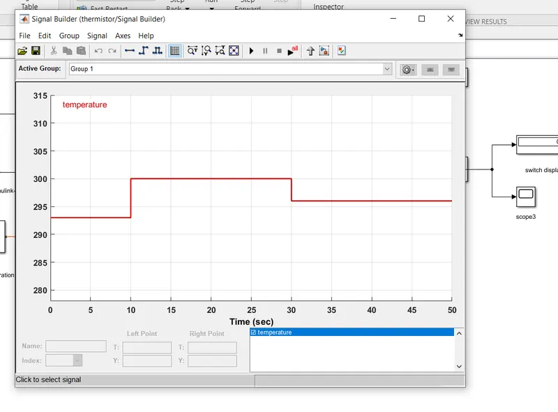
We have specified the input as per the given conditions. (293k for 0-10, 300k for 10-30, 296k for 30-50)
2. A small change needs to be done in the simulink to ps converter. Before compiling, we need to filter inputs and derivatives in the block. This can be done in the input handling menu of the block. Its photo is attached below:
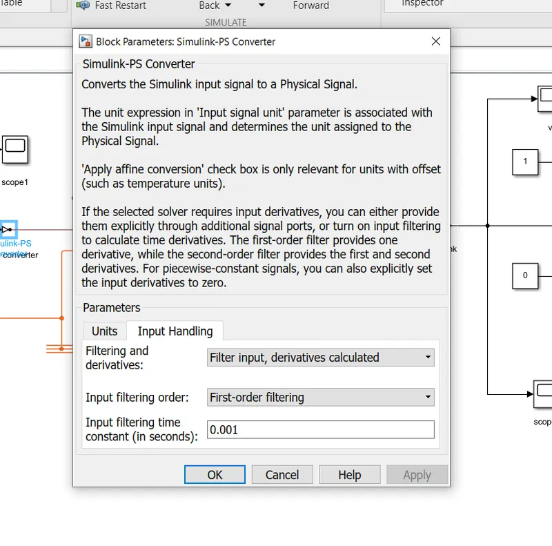
3. Make the connections as per the circuit diagram. Run the circuit for a stop time of 50 secs. The results are displayed below.
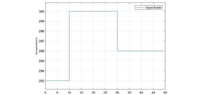
This is the plot for the input. (Temperature changing with respect to time). X-axis is the time and y-axis is the temperature.
4.
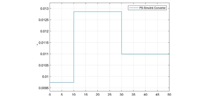
This is the voltage drop at different time instances.
5. The result display plot is also shown below, indicating the instances at which the fan was switched ON & OFF in the heater.
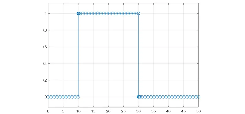
1 indicates that the fan was switched ON while 0 indicates that the SWITCH was OFF.
Thus, the simulation of a doorbell and thermistor has been explained in detail.