Week-7 Challenge: DC Motor Control
QUESTION 1:
1. Run MATLAB demo ‘Speed control of a DC motor using BJT H-bridge’. Modify the model such that armature current doesn’t shoot up when motor changes direction from forward to reverse.
Go to MATLAB documentation and type "Speed control of a DC motor using BJT H-bridge". A model will appear. Click on open model to open the circuit in the simulink window.
The block diagram will look like this.
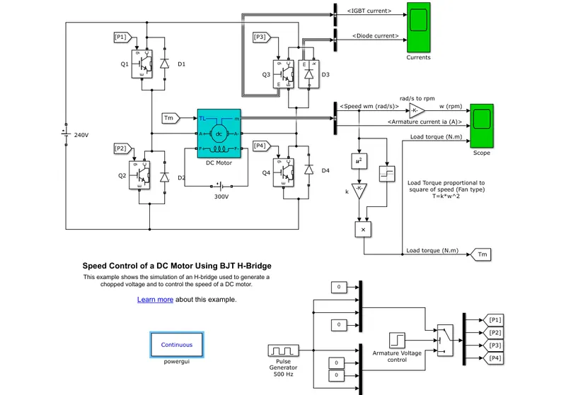
Now let us look at the explanation and working of this circuit.
The BJT (Bi-polar junction transistor) is used in power switching applications. In this circuit, the transistor operates as an IGBT(Insulated gate bipolar transistor).
There are 4 sets of diodes and 4 sets of IGBT in this circuit. A voltage source of 240V is connected.
The IGBT current and diode current coming out from the 3rd set of diode and transistor is connected to a scope window to get an idea of how the curretn flows through the transistor and diode.
The IGBT is operated as a semi-conductor device, when positive signals are given to the gate input. When a positive signal is given, a collector-emitter voltage is produced. This voltage is greater than the forward voltage Vf.
When there is zero input, the IGBT is switched off. The signals are given to the transistor with the help of a pulse generator.
The pulse generator operates at a default duty cycle of 75%. (Pulse width = 75)
A Dc motor with the preset inputs (5HP 240V 1750 RPM) is considered in this circuit.
In the another scope window, the motor speed, the armature current coming from the motor is connected. The load torque is calculated from the motor speed. Since the speed is of the fan type, the motor speed is propotional to the square of speed and it is given by the formula, T = K*w^2.
In this model of the H-bridge (The circuit arrangement of the 4 pairs of IGBT and diodes are in the form of the alphabet H, hence the name), two transistors are switched on simultaneously. Either the first set of diode and transistor(Q1) and fourth set of transistor (Q4) are simultaneously switched on, or (Q2) and (Q3) are switched on.
If Q1 and Q4 are switched on, a positive voltage is produced which is given to the motor. If Q2 and Q3 are switched on a negative voltage is produced.
The simulation time is for 1 sec. Now let us look at the results for a duty cycle of 75%.
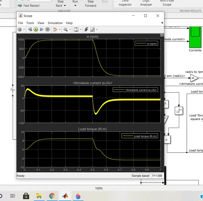
As you can see during the default duty cycle, the armature current suddenly shoots up during reverse direction. We are asked to rectify this problem. We must make sure that the current remains uniform even when motor is reversed.
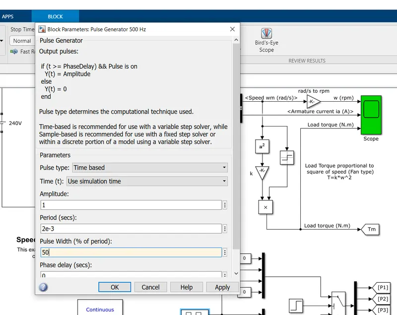
Now let us reduce the duty cycle percentage. (In this case, pulse width).
We are reducing it to 50%. Now we will look at the results.
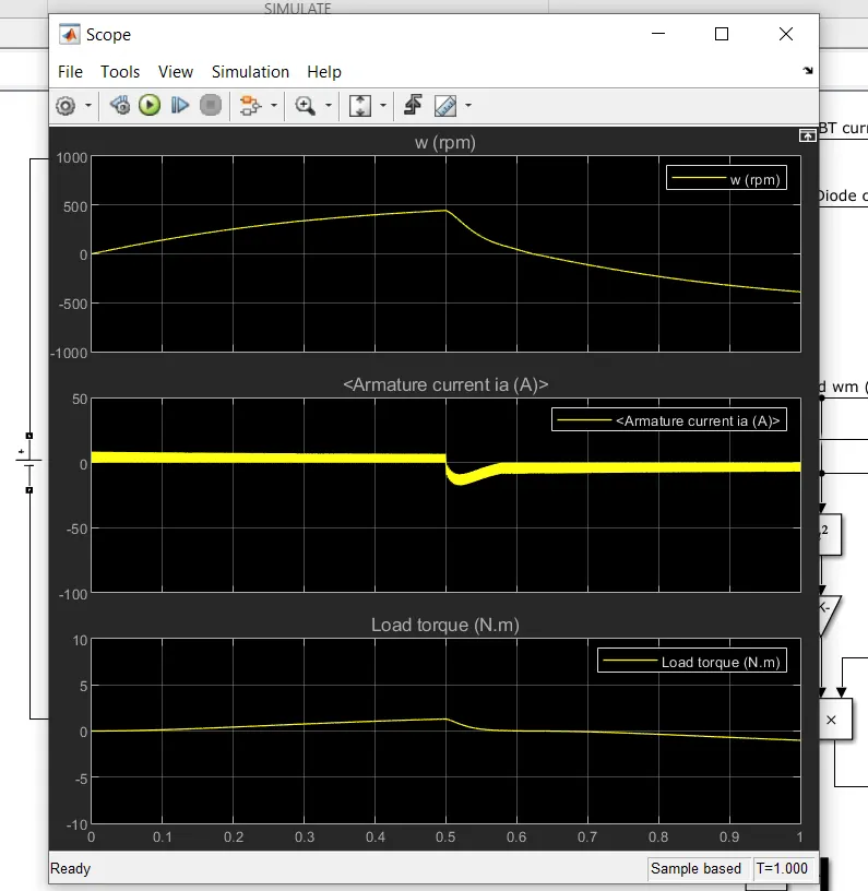
Now the armature current is more stable. Thus by reducing the duty cycle we can make the current stable in the armature of the DC motor.
We have kept the duty cycle to 35%. Now let us look at the results.
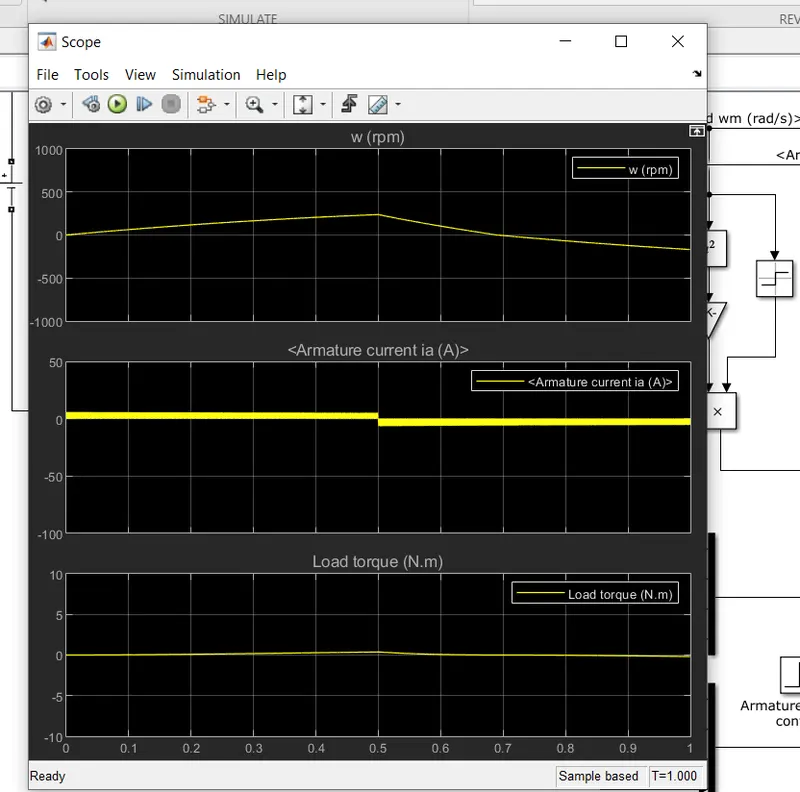
Now the armature current does not shoot up during reversing. We have fixed the problem.
QUESTION 2:
2. Refer to help section of ‘The Four-Quadrant Chopper DC Drive (DC7) block’. Compare it with H-bridge model.
To open the four-quadrant DC chopper drive block diagram, type "dc7_example" in MATLAB command window.
A block diagram appears as follows.
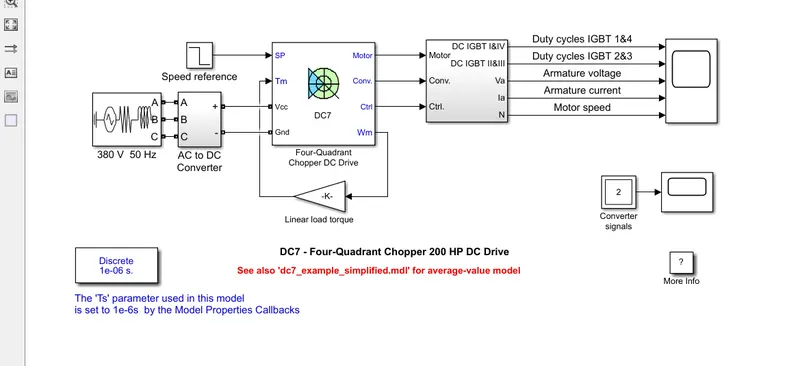
This model consists of a 3-phase AC source, a rectifier, that converts AC to DC, a four quadrant chopper DC drive and a quadrant selector.
Let us look at the circuit of a 4-quadrant chopper
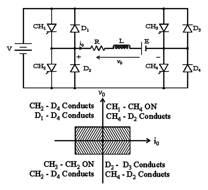
This consists of 4 pairs of choppers and diodes, a voltage source, armature resistance, inductance coil and a DC motor.
Let us look at the four quadrant operations, from the graph.
First quadrant : CH1 & CH4 are on. Armature current is positive, thus motor in forward direction. If CH1 switched OFF, energy flow is from CH4 to diode 2.(Forms closed loop)
Second quadrant : CH2 is on. Armature current is negative, thus motor in reverse direction. If CH2 switched OFF, energy flow is from diode1 to diode 4.(Forms closed loop)
Third quadrant : CH2 & CH3 are on. Armature current and load current is negative, hence motor in reverse direction. If CH3 switched OFF, energy flow is from CH2 to diode 4.(Forms closed loop)
Fourth quadrant : CH4 is on. Armature current is negative, thus motor in reverse direction. If CH4 switched OFF, energy flow is from diode 2 to diode 3.(Forms closed loop)
We are asked to compare this with the H-bridge model, that we have already discussed in detail.
In the H-bridge type, motor control is less efficient. We have to change the electric polarity, in the H-bridge model for the motor to run in the opposite direction. Regenerative braking is not applicable in H-bridge type, hence there is energy loss in this motor control. H-bridge type can control motors of lesser horsepower, hence they are not used in electric vehicles. They find applications in robotics for control of robot arms.
Now let us come to the four quadrant DC chopper control.
Here the motor control is more efficient. The main purpose of a four quadrant dc chopper drive is that it can operate in all four quadrants. Here in this drive forward motoring, reverse motoring, forward regeneration and reverse regeneration all are possible. They are the ones widely used in EV's as they can control higher horsepowers.
Motor control is acheived in dc7 drives by interrupting one signal input under control of another.
The circuit is more complex in dc7 drive as this requires more number of power switching devices.
QUESTION 3:
3. Make a suitable EV model using DC7 block and make result report.
Open the dc7 block diagram.
The default block diagram looks like this.
This model is designed for an 3-phase AC power supply source. We have to change it to EV model.
This can be done by adding a constant DC power source (A battery equivalent), a drive cycle and a speed-torque characteristic.
In order to convert this model for an EV, we have to add a constant electrical power source.
Use the dc voltage source block to create a constant power source. Remove the AC supply and the AC to DC converter.
We have also added a current measurement device and a scope to get an idea of the current supply to the chopper drive throughout the simulation time.
Next add a user defined drive cycle data. Remove the speed reference block and import a drive cycle data into the model using the from workspace block.
Now we have to add a speed-torque characteristic to the chopper DC drive. Use the relation T = 24.7 + 0.0051*w^2 and use the add, gain, constant & square block to plot the equation and create a subsystem.
Connect the subsystem with the speed port and the torque port of the DC chopper drive. Now the circuit looks like this.
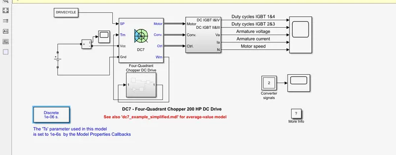
Now the simulation time is set to 20secs, as we have prepared the drive cycle data for 20 secs.
After running the block diagram, MATLAB starts plotting the motor speed, armature current and voltage, duty cycles for the IGBT choppers 1, 2, 3 & 4 within the DC chopper drive.
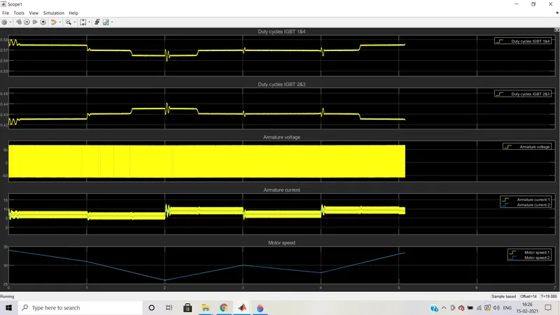
We see how the motor accepts current during acceleration and deceleration, the duty cycle time during the operations, the current and voltage through the armature etc.
QUESTION 4:
4. Explain in a brief about operation of BLDC motor.
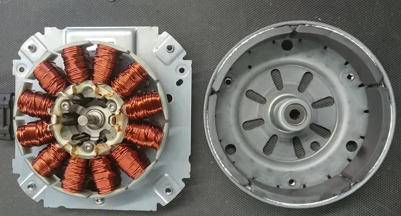
A brushless DC motor (also known as a BLDC motor or BL motor) is an electronically commuted DC motor which does not have brushes. The controller provides pulses of current to the motor windings which control the speed and torque of the synchronous motors.
These types of motors are highly efficient in producing a large amount of torque over a vast speed range. In brushless motors, permanent magnets rotate around a fixed armature and overcome the problem of connecting current to the armature. Commutation with electronics has a large scope of capabilities and flexibility. They are known for smooth operation and holding torque when stationary.
Before explaining the working of a brushless DC motor, it is better to understand the function of a brushed motor. In brushes motors, there are permanent magnets on the outside and a spinning armature which contains electromagnet is inside. These electromagnets create a magnetic field in the armature when the power is switched on and help to rotate the armature.
The brushes change the polarity of the pole to keep the rotation on of the armature. The basic working principle for the brushed DC motor and for brushless DC motor are same i.e. internal shaft position feedback.
Brushless DC motor has only two basic parts: rotor and the stator. The rotor is the rotating part and has rotor magnets whereas stator is the stationary part and contains stator windings. In BLDC permanent magnets are attached in the rotor and move the electromagnets to the stator. The high power transistors are used to activate electromagnets for the shaft turns. The controller performs power distribution by using a solid-state circuit.
Below is a simple animation on how a BLDC motor works.
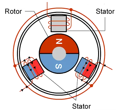
This is how a brushless DC motor works.