Project 1 Mechanical design of battery pack
INTRODUCTION:
Lithium-ion batteries power the lives of millions of people each day. From laptops and cell phones to hybrids and electric cars, this technology is growing in popularity due to its light weight, high energy density, and ability to recharge.
WORKING:
A battery is made up of an anode, cathode, separator, electrolyte, and two current collectors (positive and negative). The anode and cathode store the lithium. The electrolyte carries positively charged lithium ions from the anode to the cathode and vice versa through the separator. The movement of the lithium ions creates free electrons in the anode which creates a charge at the positive current collector. The electrical current then flows from the current collector through a device being powered (cell phone, computer, EV etc.) to the negative current collector. The separator blocks the flow of electrons inside the battery.
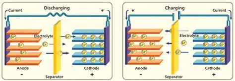
While the battery is discharging and providing an electric current, the anode releases lithium ions to the cathode, generating a flow of electrons from one side to the other. When plugging in the device, the opposite happens: Lithium ions are released by the cathode and received by the anode.
A group of battery cells connected together constitute a battery pack. The need for a battery pack is because a single battery cell cannot provide enough power to run an EV.
We are asked to create a battery pack containing the ANR26650M1-B cells. Now let us look at this cell type & its parameters.
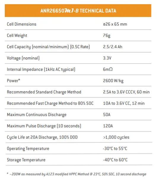
The cell type ANR26650M1-B means that this battery cell is a secondary cell (rechargeable type) with a cell diameter of 26mm and a cell height of 65 mm. The above screenshot displays the complete cell parameters.
The above datasheet is provided by A123, a company that manufactures Li-ion cells.
Before proceeding to model a battery pack, we must calculate certain aspects based on some assumptions. Inorder to design a battery pack, we must calculate the following:
1). Energy required from the battery pack.
2). Number of cells that must be in the battery pack.
3). Battery capacity.
4). Current supplied by the pack.
5). Battery range. (In terms of kms.)
6). Weight of the total battery pack.
7). Dimensions of the battery pack.
ENERGY:
It is already given in the question that the battery energy must be 18KWh.
NO. OF CELLS:
This can be found out from the formula,
N = Energy/(Nominal voltage*capacity).
where, N=No of cells.
Nominal voltage = 3.3V & Battery cell capacity = 2.5Ah from the cell datasheet.
N = 18000/(3.3*2.5)
N = 2182. So we must have 2182 cells in the battery pack. Now we must derive the battery pack architecture.
Let us assume that we must need a nominal battery pack voltage of 300V. We already know that the battery cells connected in series will increase the voltage. Hence, the no.of cells in series will be calculated by,
Ns = (Battery pack voltage)/(nominal voltage of one battery cell).
Ns = 300/3.3 = 91.
Hence 91 cells connected in series will generate a battery pack voltage of 300V.
Now, the cells connected in parallel is calculated by,
Np = 2182/91 = 23.9 = 24 cells.
Hence the battery pack architecture is 91s24p.
BATTERY CAPACITY:
We know that cells connected in parallel will increase the current. The cell capacity is given as 2.5Ah. There are 22 parallel rows of cells in the battery pack. Hence, the rated capacity of the pack becomes,
Capacity = (Individual cell capacity)*(No.of parallel rows)
C = 2.5*24 = 60Ah. Hence the capacity is 60 Ah.
CURRENT SUPPLIED BY THE PACK:
Consider a 1C rate as the charge & discharge rate. The capacity of the pack is 60Ah meaning that the pack supplies current of 60A for one hour.
BATTERY RANGE:
Consider the assumption of powertrain energy consumption per kilometer of the EV.
Based on certain real time EV models, the powertrain energy consumption = 110Wh/km.
Battery range is given by = (Energy of the pack)/(powertrain energy consumption)
= 18000/110 = 163.6Km.
Hence the battery pack will withstand for 163 kms without charging.
WEIGHT:
From the datasheet, it is given that the cell weight is 76g. We have a pack of 2182 cells. And there will be accesories such as BMS, Metal strips, wires etc. Consider these accessories having a weight of 10g. The total weight of the battery pack is:
Weight = Individual cell weight * No of cells + Accessories
Weight = 76*2182 + 10 = 165.8 Kg.
DIMENSIONS:
Battery packs have some enclosures for protection from heat & other environment factors. The enclosure dimensions must be calculated before fabrication. This is done based on cell dimensions.
Our battery cell has dimensions of 26 x 65 mm. Let us calculate the length, breadth & height of the enclosure.
Length = (No.of cell colomns connected in series*cell diameter) + clearance of the cells at sides.
Let the clearance be 5mm between each cells.
Length = 91*26 + 5*91 = 2821mm.
Also the battery pack's BMS is attached at the sides of the battery pack. So we must need an additional clearance of atleast 100mm. So the total length would be 2921mm.
Similarly the breadth is calculated by,
Breadth = (No.of cell rows connected in parallel*cell diameter) + clearance of the cells at sides.
Breadth = 22*26 + 5*91 = 1027mm.
Height is determined by,
Height = Individual cell height + Margin for pack accessories
Consider the margin for pack accessories (wiring,cell holders etc.,) to be 30 mm.
Height = 65+30 = 95mm.
Now we have calculated all the parameters required for the construction of the battery pack. Now let us look at how the battery pack is modelled.
Let us look at what are required to manufacture a battery pack. The components include:
1). Battery cells
2). Nickel strips.
3). Heat sink.
4). Welder.
5). Connectors.
6). Cell holders.
We will look at the step by step manufacturing of the battery pack.
STEP1:
The first step would be the preparation of cell holders. These cell holders are the ones used to hold the cells together in a battery pack. It's picture is attached below.
These cell holders are manufactured based on no.of cells present in the battery pack & the individual cell dimensions. The type of material used as cell holders are generally plastic.
The above picture is an example of how a cell holder looks like.
STEP2:
After the cell holders are prepared, the battery cells are loaded into the cell holder one by one. The loaded cells in a cell holder will look like this.
STEP3:
The next step would be connecting the cells together with nickel strips. The reason why nickel strips are connected between cells is because nickel has low resistance & it is easier to weld. The battery cells are connected with nickel strips using spot welding. The series connection is made by connecting positive to negative terminal & the parallel connection is made by connecting same terminals.
STEP4:
After the cell connections are made, the heat sink is pasted to the pack. The heat sink material can be metal or PVC. Generally, PVC heat sinks are preferred as their thermal performances are good compared to metals. Plus, if the heat sink and the battery cells are of different materials, there will be lesser damage. The heat sink takes care of the thermal management of the battery pack.
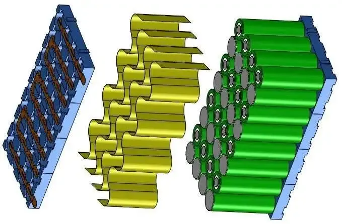
The material yellow in colour is the PVC heat sink. It is generally pasted below the pack.
STEP5:
The next step is the soldering of balancing wires & connecting the BMS to the battery pack. It is a known fact that we must connect a BMS outside the battery pack. They are used to operate the battery cells at safe conditions. These connections are made with the help of balancing wires. The use of balancing wires is to reduce the noise when these wires are used to send signals from the BMS to the battery cells.
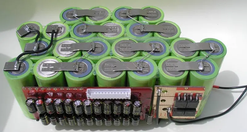
The wires that are red & black in colour are the balancing wires. The BMS is connected with the current supply wires of the pack & then glued to the side of the battery pack.
STEP6:
The final step would be to wrap the entire battery back using an enclosure material. These enclosure materials are generally plastic papers or metal sheets. We already know how to calculate the dimensions of enclosure for a battery pack. These values are taken into account & then modelled.
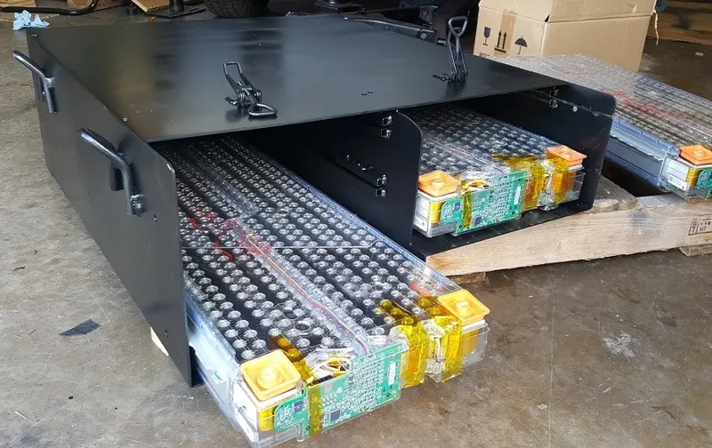
We can see the transparent covers wrapped around the battery pack. The plastic wrappers are the best enclosures used for battery packs.
This is how the battery pack is modelled.
A table is created which shows the battery pack parameters.
| PARAMETERS | CELL LEVEL | BATTERY PACK LEVEL |
| DIMENSIONS | 26 X 65 mm | 2920 x 1027 x 95 mm |
| WEIGHT | 76g | 165.8 kg |
| CAPACITY | 2.5Ah | 60Ah |
| VOLTAGE | 3.3V | 300V |
| ENERGY | 0.008KWh | 18KWh |
| ARCHITECTURE | NIL | 91s24p |
| RANGE | 0.074Km | 163.6Km |