Project 1
AIM:
1. To extract the mid-surface of the given component(IP substrate).
2. To also mesh the given component and assign thickness to the FE model.
PROCEDURE:
1. PERFORMING THE TOPOLOGY AND GEOMETRY CLEAN-UP:
a). The given component is an instrument panel substrate of a vehicle. It is an important part of the vehicle since it displays the controls of a given vehicle. This is what we are going to model in this project. Importing the model in the ANSA software will look like this.
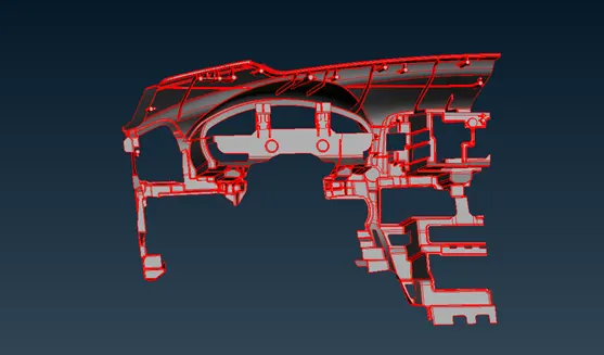
After importing the model, refine the model to a length of 1mm and eliminate single cons using the FACES-TOPO option.
b). The model will be having unchecked faces, single cons and cracked cons, triple cons and needle faces. Go to the CHECKS manager and execute the model for these errors. Use the AUTOFIX option to clear all the existing errors that ANSA has found.
c). However the unchecked faces might still be present even after executing the AUTOFIX command. In such cases, manual intervention is the only method. Add and delete faces appropriately using the FACES-NEW and FACES-DELETE.
d). After clearing all geometrical errors, our model will now look like this.
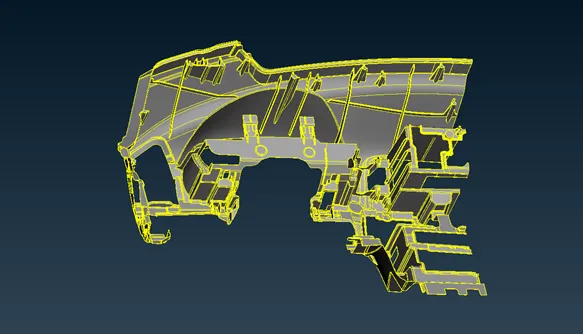
Now that our model is clean, we can proceed to the mid-surface.
2. EXTRACTING THE MID-SURFACE:
a). This is a plastic trim component. Using auto mid-generation methods might result in bad mid-surface and meshing. Manual mid-surface generation is the safer option. In this model, there are many ribs and dog house features. So we may have to extract them and extend them with the base mid surface. Let us look at the various features of the model.
b). The base mid-surface of the IP substrate must be taken first. It is of 0.6mm thickness and can be captured in a single shot using the FEATURE AREA selection. Use the FACES-OFFSET option to extract the mid-surface. After extracting, it will look like this.
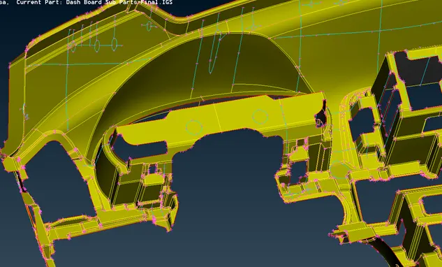
Store this mid-surface in a seperate PID and enter the thickness value as 0.6mm.
c). Now let us look at the doghouse features. The picture is attached below.
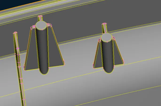
For these features, we have to extract the cylinder first and the ribs that are attached to it. Since the cylinder is a hollow part, we cannot measure the thickness and offset. However, to replicate the feature, we can offset the cylinder to a distance of 1mm inside and use the CURVES-MIDDLE option for the ribs attached around the cylinder.
d). Use FACES-OFFSET option for extracting the cylinder. After that, extend the ribs to the cylinder and to the base mid-surface. Now our mid-surface will look like this.
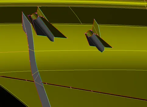
Store the cylinders and the ribs in seperate PID's.
e). Now let us look at extracting the mid-surface for longer ribs. A photo of a larger rib is attached for reference.
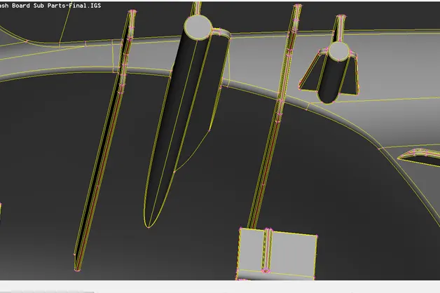
These ribs can be extracted using the CURVES-MIDDLE option and then creating a new face from those curves. The cons on the upper edge of the ribs are the reference lines for extracting the middle curves. A zoomed photo is shown below for better understanding.
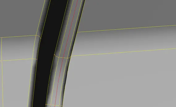
The cons next to the red line that passes through are the reference cons for the middle curve. Create the curve throughout and make a closed entity. After doing that, use the FACES-NEW and COONS suboption to create a mid-surface exactly in the middle.
e). Some more additional features are present in this model. Since they are hollow, offset those features to a distance of 1mm, similar to the cylinder doghouse model. Their photos are attached below.
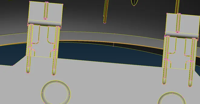
The ribs and the base surfaces attached to those can be extracted using the curves middle option. The fillet regions and the circular features can be extracted using FACES-OFFSET option and the offset distance can be specified as 1mm. The mid-surface pictures are attached below.
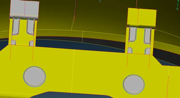
f). Make sure to extend the features to the base mid-surface. Use the FACES-EXTEND and the FACES-INTERSECT option to perform these tasks.
g). Make sure that all the features are stored in different PID's. The property manager list is attached below so as to identify the different features according to their thickness.
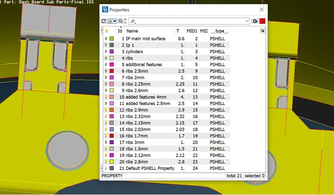
Our mid-surface extraction is done and we can proceed to the meshing.
3. MESHING THE EXTRACTED MID-SURFACE:
a). Now we must know our quality criteria before meshing. The quality parameters of the model are given below.
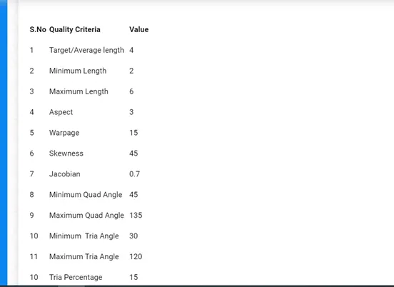
b). Since the target element length is given as 4mm, we need to refine the entire model to a value of 4. Use the PERIMETERS-LENGTH option in the mesh module to refine the model.
c). Enter the values given above in the quality criteria tab. A photo is attached for reference.
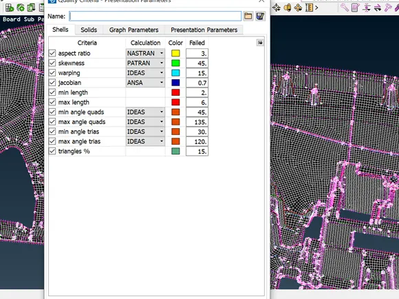
d). Now perform necessary defeaturing on the model. Since our min.length is 2, delete construction lines that have width less than 2mm. Also remove unnesessary hot points.
e). Mesh the component area by area and clear off elements that appear. Use RECONSRTUCT, RESHAPE and SMOOTH options available under SHELL MESH.
f). Make sure to have a good mesh flow throughout. However, the areas where featurers are extended will disturb the mesh flow and also will lead to off elements.
g). For example, areas where there are no additional features extended will have a better mesh flow.
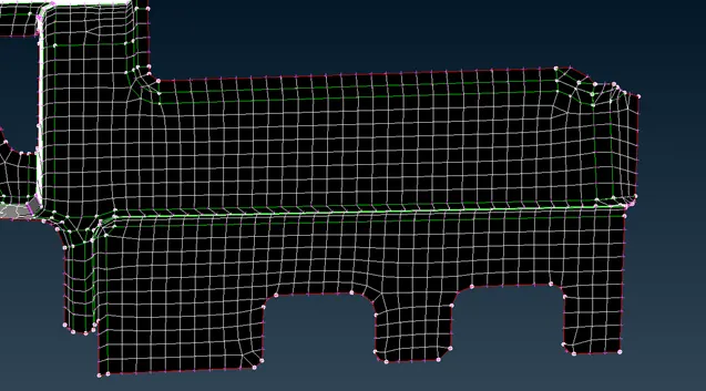
In this above picture, since it is a flat area, the mesh flow is good and there are lesser tria elements. In some doghouse areas, because of the extension to the mid-surface there will be certain off elements created.
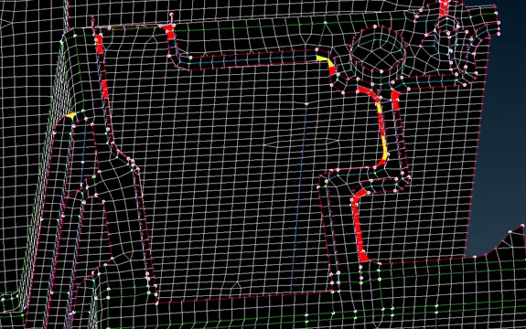
In the above picture because of the ribs and cylinders, there are elements failing for min.length and aspect ratio. Try to clear off elements in these areas. If not atleast have a better mesh flow.
h). Try to avoid tria elements in the perimeters and hole regions. Use ELEMENTS-SPLIT and SWAP options to handle tria elements from falling into these areas.
i). After meshing use the DRAW SHELL AS SOLID to view our FE model as a solid. Compare it with our parent surface and check if they are matching.
Thus the modelling of the IP substrate is done.
LEARNING OUTCOMES:
1. We learnt on how to model a larger model like the IP substrate.
2. We also learnt on how to extract mid-surfaces for hollow features and ribs.
3. We learnt on how to mesh in areas where features are extended.
CONCLUSION:
There will be off elements generated at feature areas and extended mid-surfaces. In such areas quality criteria will not be satisfied fully. Try to eliminate the off elements as much as possible.