Week 11 Car Crash simulation
Car Crash Simulation Using Ansys
Objective: To perform a parametric analysis of a Frontal car crash setup and determine the effect of varying the thickness of the model on Equivalent Stress and Total deformations.
Case_1-0.3mm.
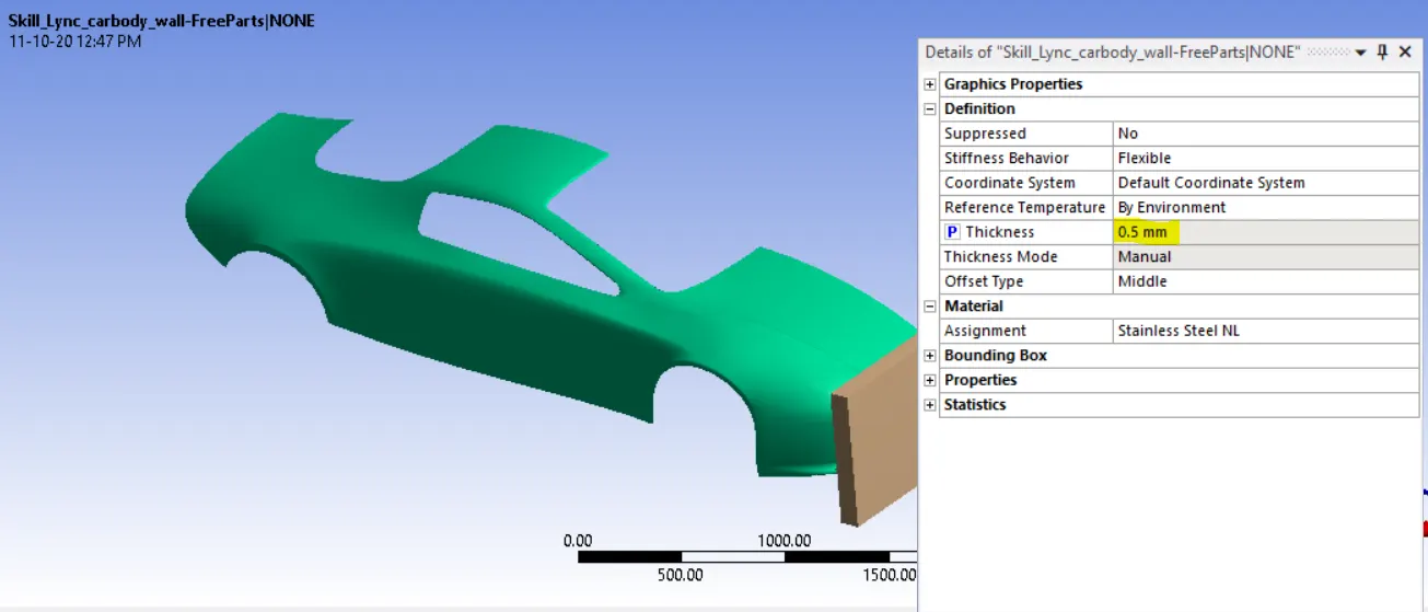
Case_2- 0.5mm
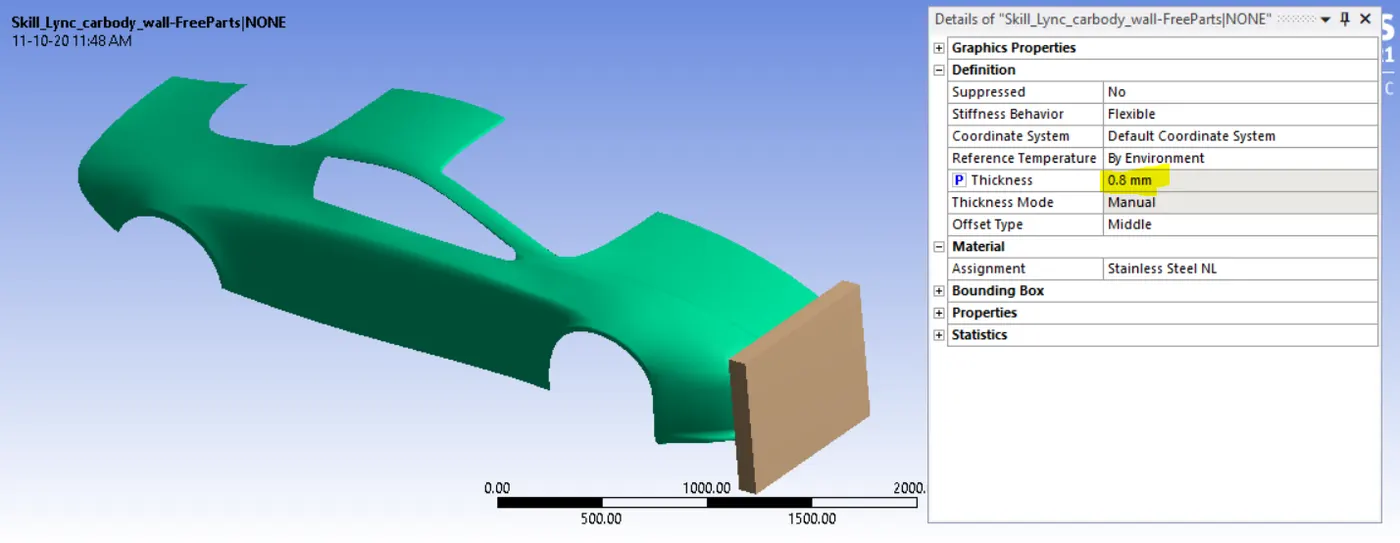
Case_3- 0.8mm
Simulation Process:
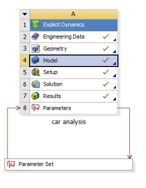
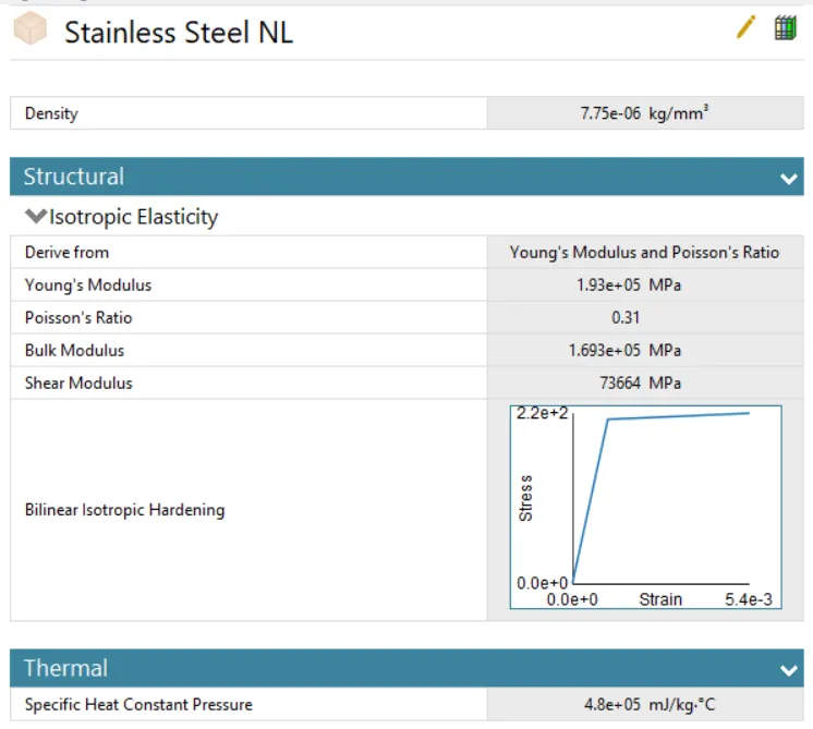
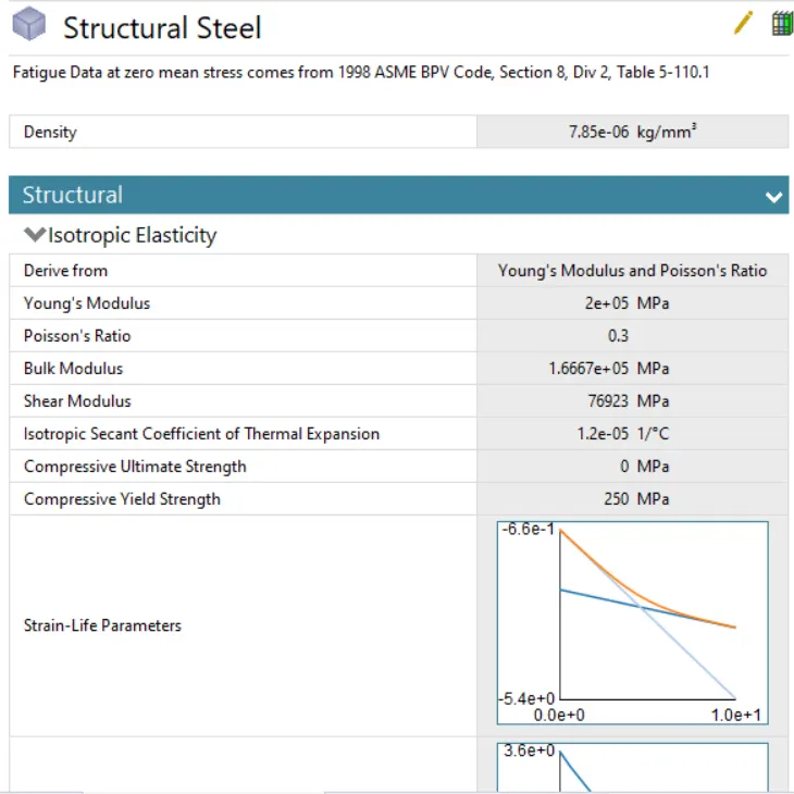
Create Explicit Dynamics in Ansys workbench and in engineering data select Select Stainless Steel NL and Structural Steel
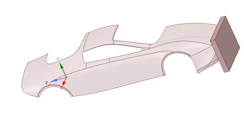
Input Geometry
Import the geometry and check in space claim for any irregularities
Then open Ansys mechanical and rename the component as Car Body and Wall then assign the Stainless Steel NL material to the Carboy and Structural Steel material to the cases to the Wall
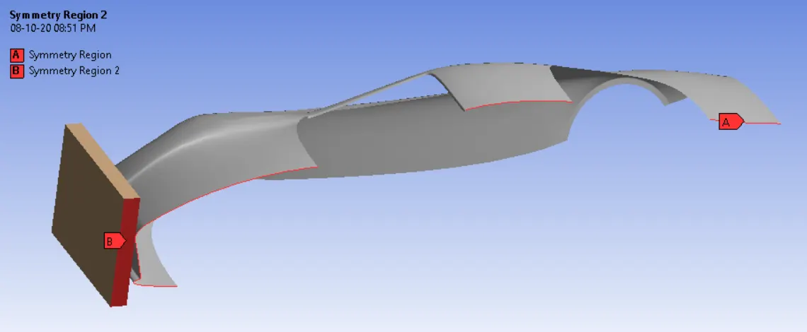
Symmetry Definitions- The entire setup mentioned above represent just half the model the analysis is carried out on a Half model to reduce computations time. To get results for the full model, two symmetry regions are defined about which the results of the half model are duplicated.
Mesh
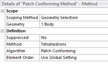
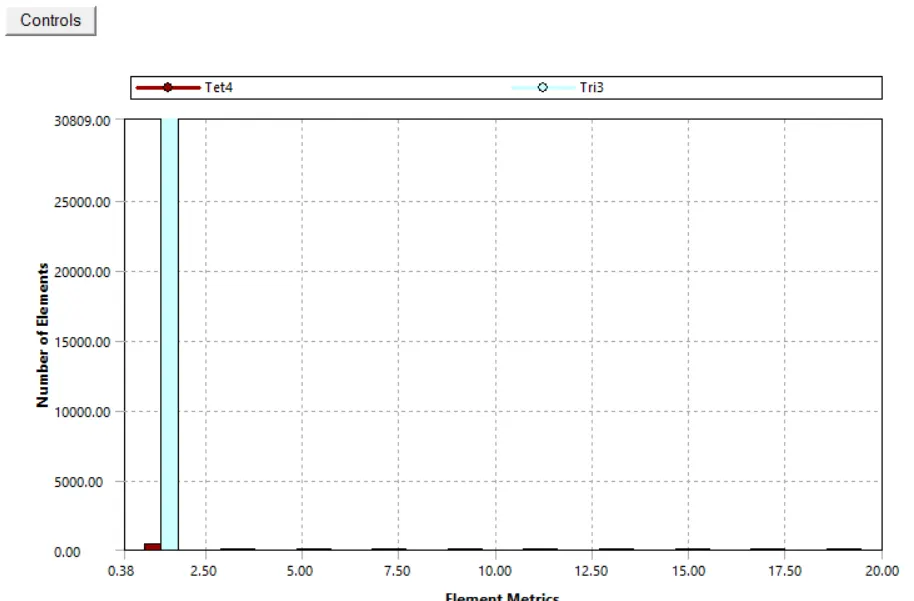
- The wall is meshed using Tetrahedron and by patch Conforming Method and car Car body By Using default
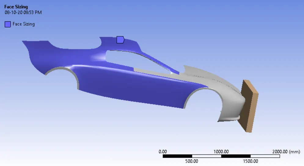
Face sizing- Face sizing options used. At the back side of car body
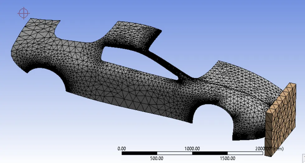
Final Mesh-
Boundary conditions
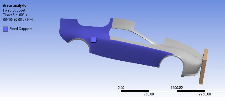
Fixed support- Rear surface of the car Body are provided a fixed Support
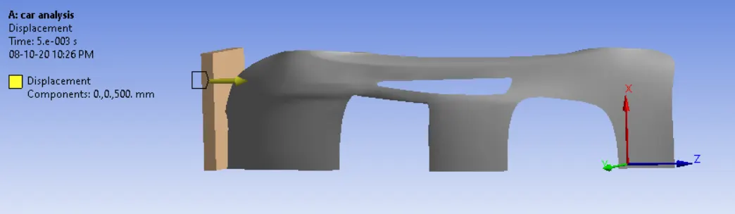
Displacement- Wall is provided a displacement of 500 mm in the Z-direction
Analysis setting:
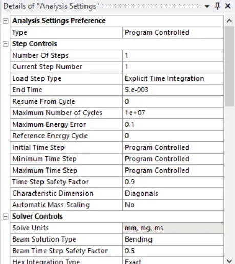
- Set end time as 5e-003, and all the setting set to default.
Parameter Definition- Instead of running separate simulations to get the results, parametric options used. The thickness of the Car Body is set as the input parameter
For the output Parameter, the Total Deformation and Equivalent Stress and Equivalent Stress on the car Body are set as the output parameters
Solutions:
All the necessary output variable are selected such as von Mesis stress, stress intensity, equivalent strain etc.
Result – The analysis runs successfully and results obtained.
The project interface page appears as below, with a Parameter set option. Double clicking that options open up the results to the simulations
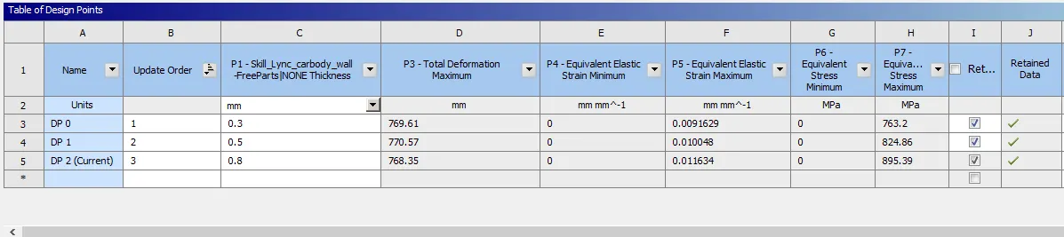
The results page from the Parameter set page appears as below
Case_1- 0.3 thickness
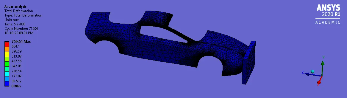
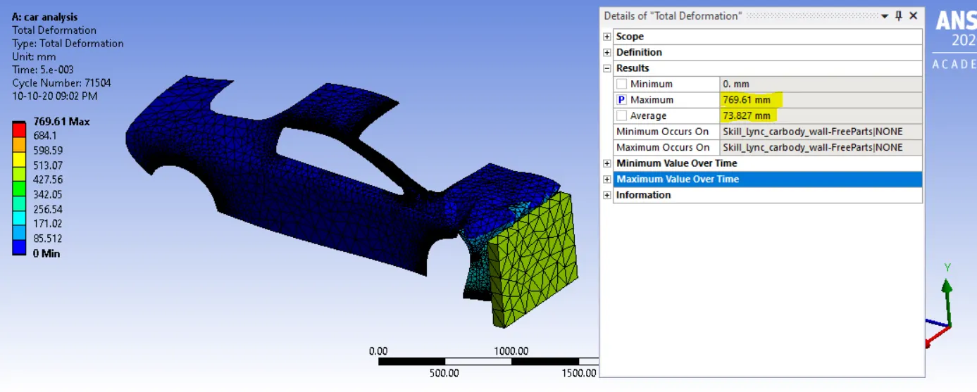
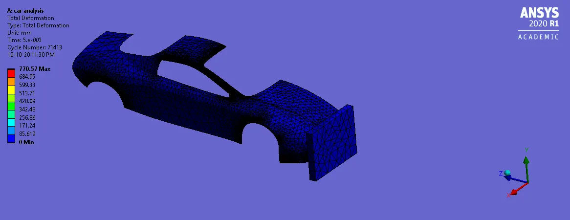
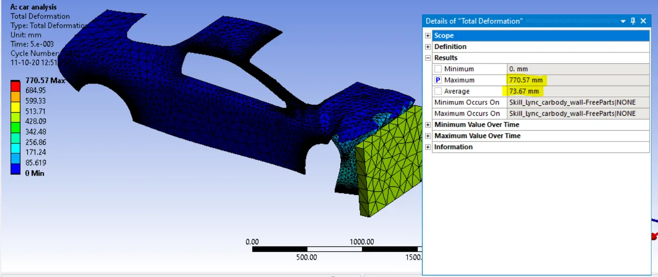
Total Deformations
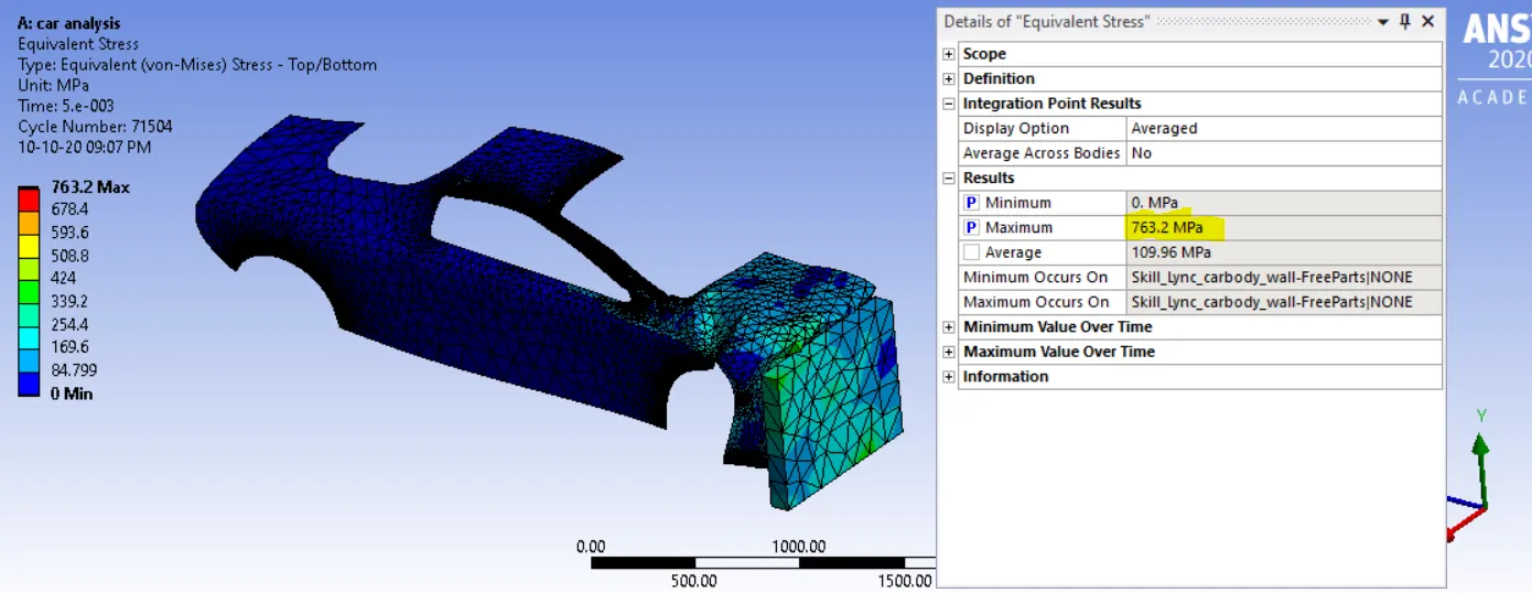
Equivalent stress
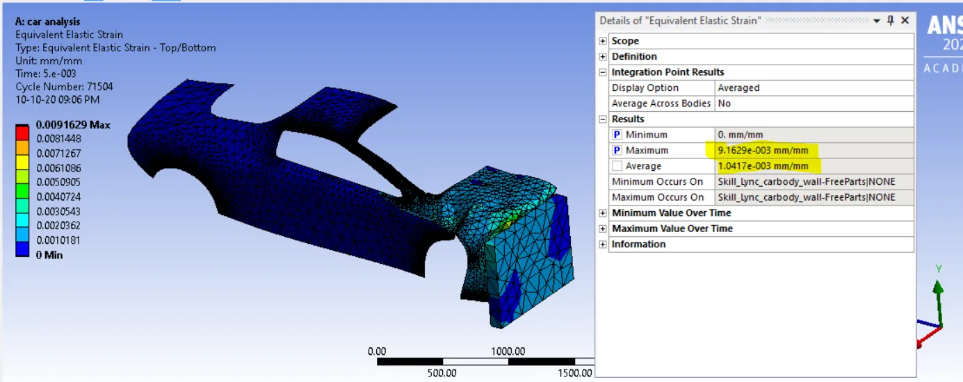
Equivalent strain
Case_2- 0.5 thickness
Total Deformations
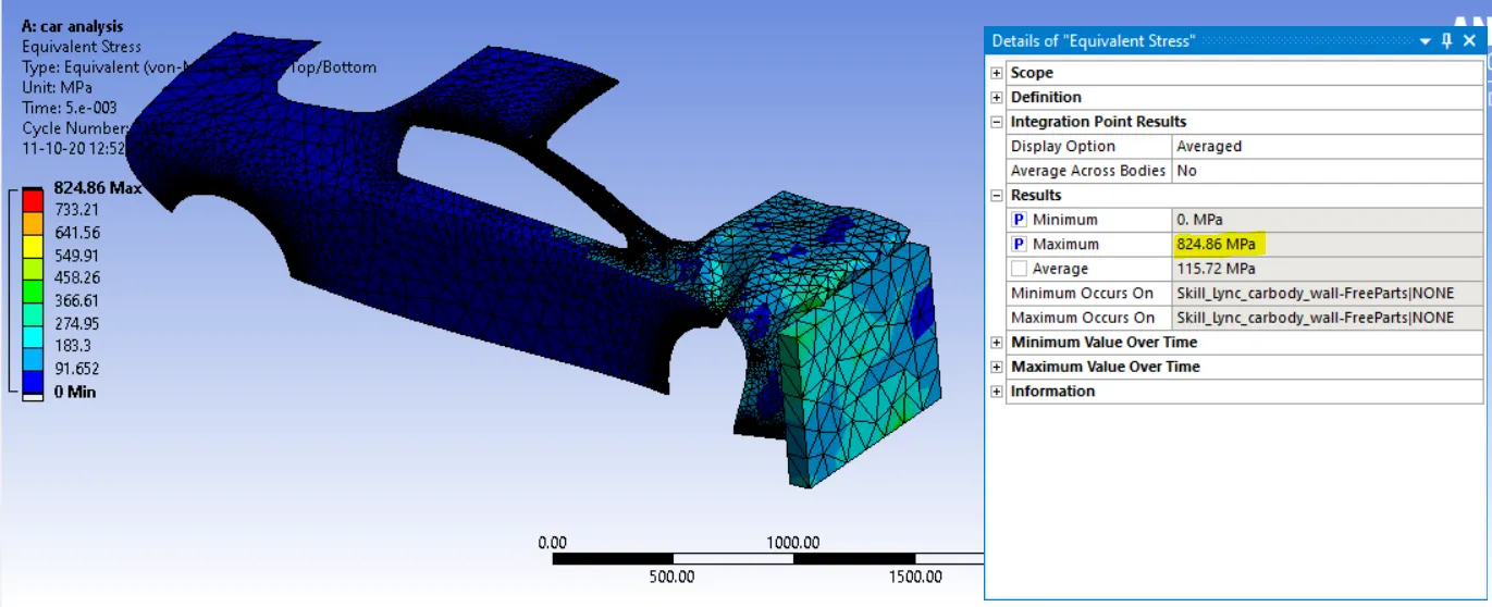
Equivalent stress
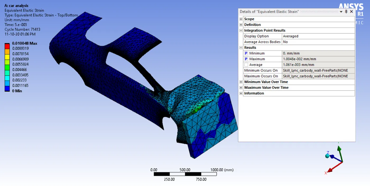
Equivalent strain
Case_3- 0.8 thickness
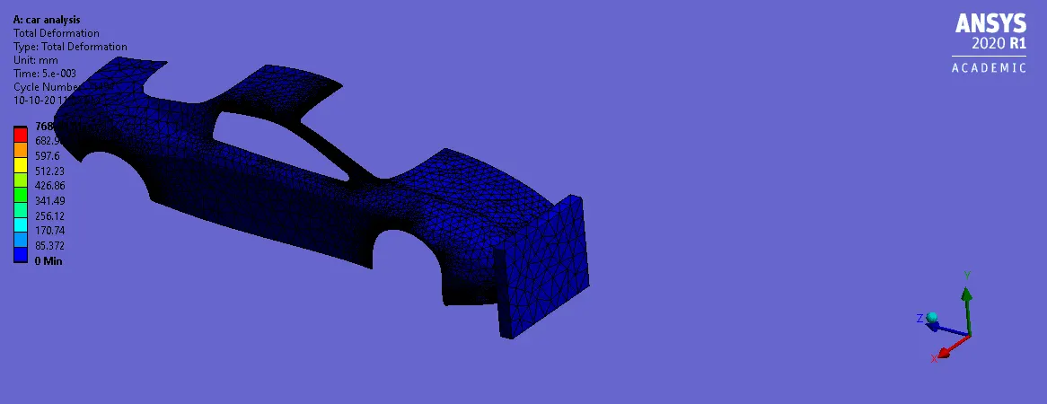
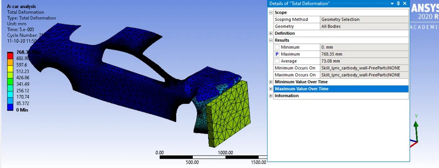
Total Deformations
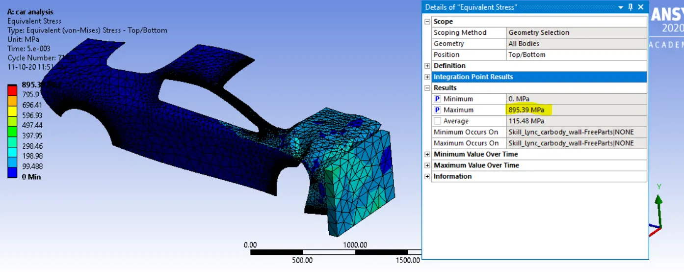
Equivalent stress
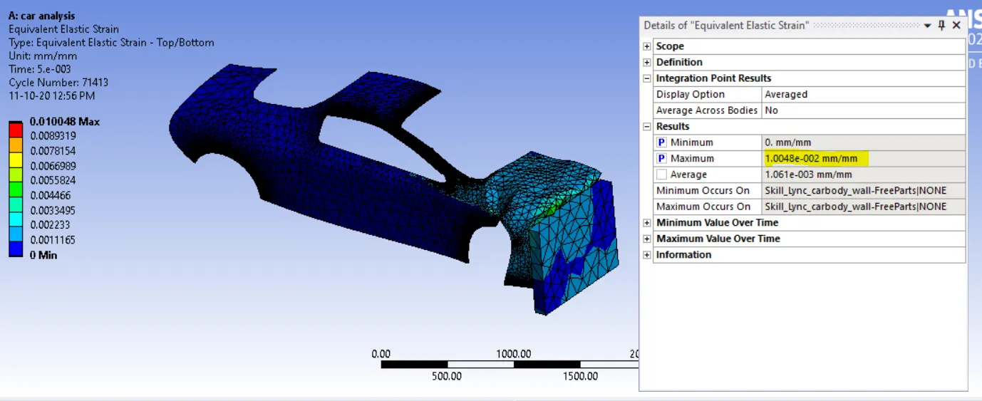
Equivalent strain
Observations
| Total Deformation Max | Equivalent Stress Max | Equivalent Strain Max | |
| case1_0.3 | 769.71 mm | 763.2 Mpa | 9.1692e-003mm/mm |
| case2_0.5 | 770.57 mm | 824.86 Mpa | 1.0048e-002 mm/mm |
| case3_0.8 | 768.35 mm | 895.39 Mpa | 1.1634e-002 mm/mm |
Conclusions:
Maximum deformation is developed for Case1-0.3mm because of lowers stiffness or rigidity to resist deformations.
Maximum Stress is developed for case 1-0.3mm because it has minimum thickness so induces maximum stress due to less resisting area. The model experiences the highest Von-Mises stress when the thickness of the shell is the least
We can clearly see that when the thickness of the car body increase the deformation decrease. As the thickness increases the Strain value decrease.