Week 7-Long Piston With Cam
Transient Simulation of a long Piston cam Mechanism Model Using ansys Workbench.
Objective: Transient simulations on a piston and cam mechanism model with three different cases
Case1- Frictionless contact,
Case2- Friction co-efficient 0.1
Case3-Friction coefficient 0.2
Procedure: create Transient structural analysis and in engineering data select the material structural steel.
Material:
The material used for the entire simulations was structural steel
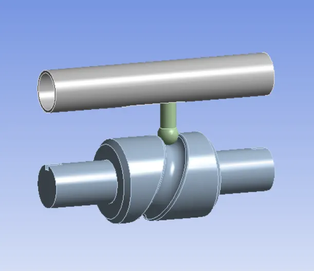
Input Geometry
The given module was inserted into the mechanical GUI. Check in space claim for any defeat in model
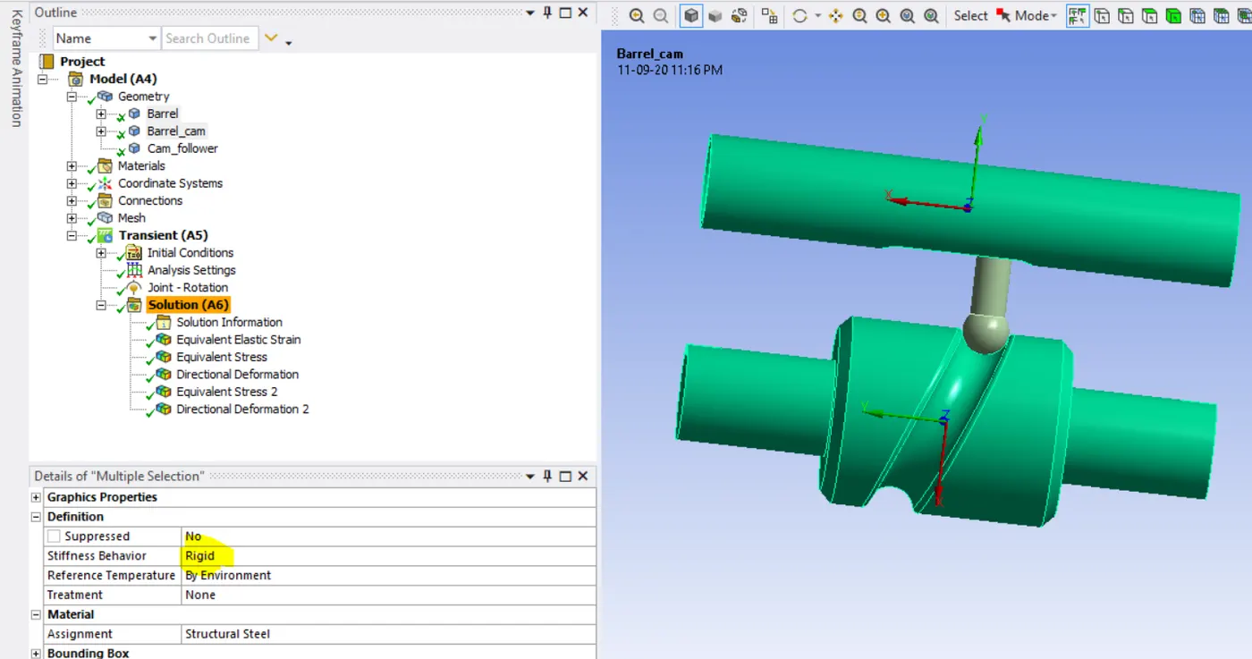
Then open Ansys mechanical and rename the geometry as Barrel, Barrel CAM and CAM Follower then assign the Structural steel material make stiffness Behaviour as Rigid
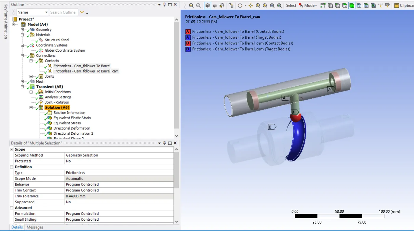
Contacts:
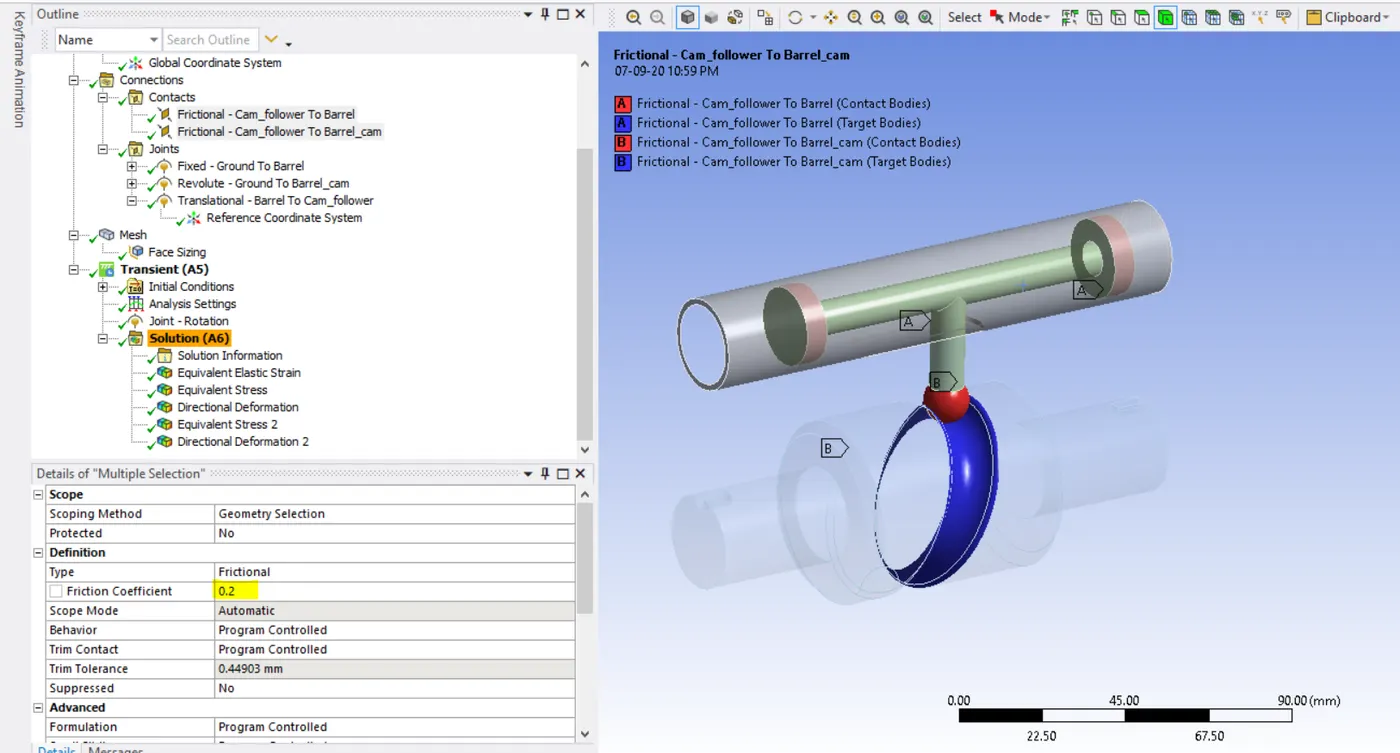
Two contacts created in the whole setup with frictionless or frictional type with friction coefficient of 0.1 and 0.2 and interface treatment is set to add offset, Ramped effect
Case1-Frictionless contact
Case2-Fricitional with 0.1 as the frictional contact
Case3-Fricitonal with 0.2 as the frictional contact
Joints:
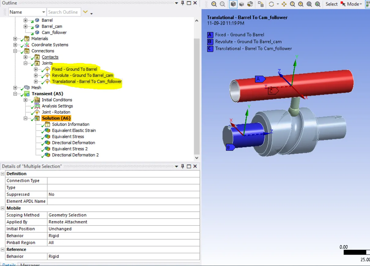
Three joints created in whole geometry
Fixed-Ground to Barrel, Revolute- Ground to Barrel CAM, Translational- Barrel to Cam_ Follower
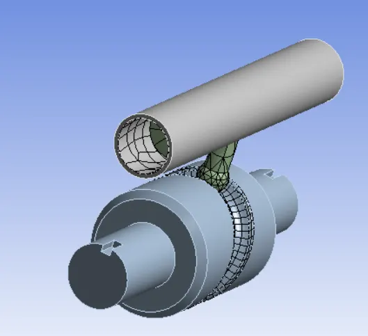
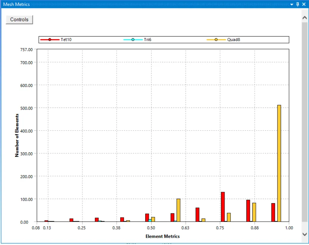
Mesh- Face Sizing option use for meshing 3mm element size
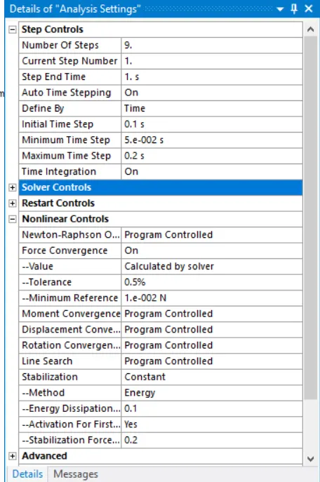
Analysis setting- the simulations run for 9steps. so, the number of steps is set as 9.In the first step large deflection set to on and defined by time. initial time step to 0.1s, Minimum time step set to 5e-2s and Maximum time set to 0.2s and stabilization set to constant , method to energy and energy dissipation ratio to 0.1,activations for first steps to yes. In output contact set all output to yes
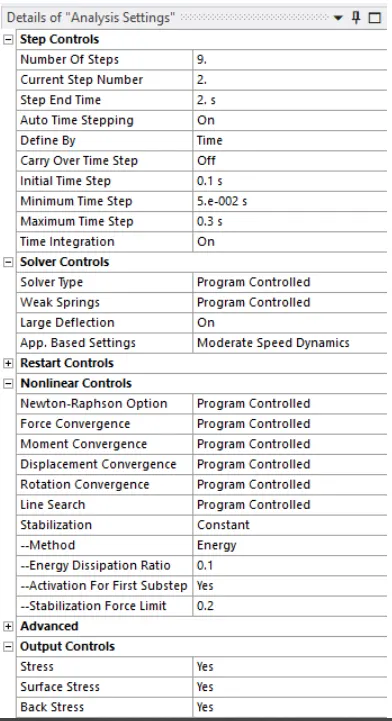
The second steps to nine step large deflection set to on define by time. Carry over time set to on, initial time steps set to 0.1s, Minimum time steps set to 5e-2s and Maximum time step set 0.3s and stabilization set to constant , method to energy dissipation ratio to 0.1, activation for first steps to yes. In output contact set all output to yes except contact miscellaneous
Boundary conditions
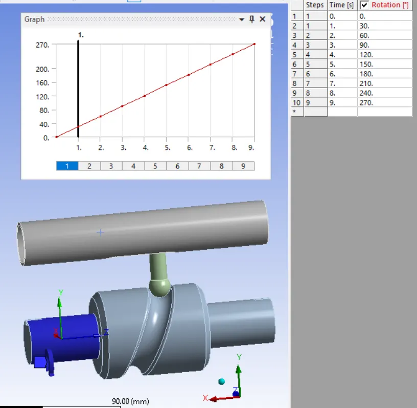
Joint –rotation –cam is provided a rotation of 270 degrees
Solutions:
All the necessary output variable are selected such as von Mesis stress, stress intensity, equivalent strain etc.
Result –
Case1-Frictionless contact
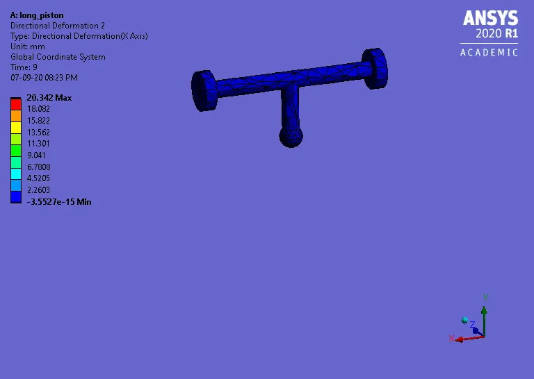
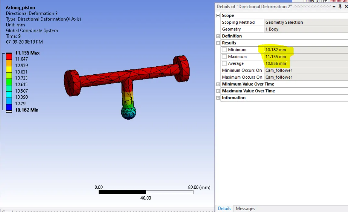
Directional Deformation a axis
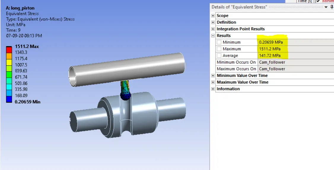
Equivalent stress
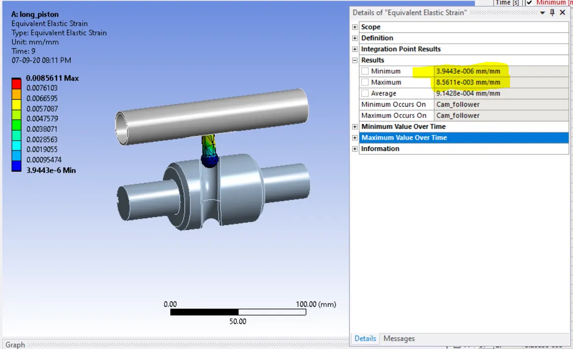
Equivalent elastic strain
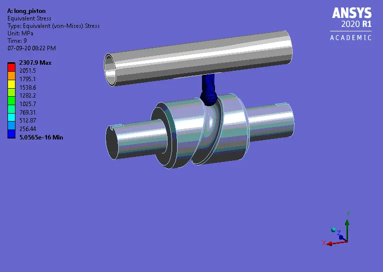
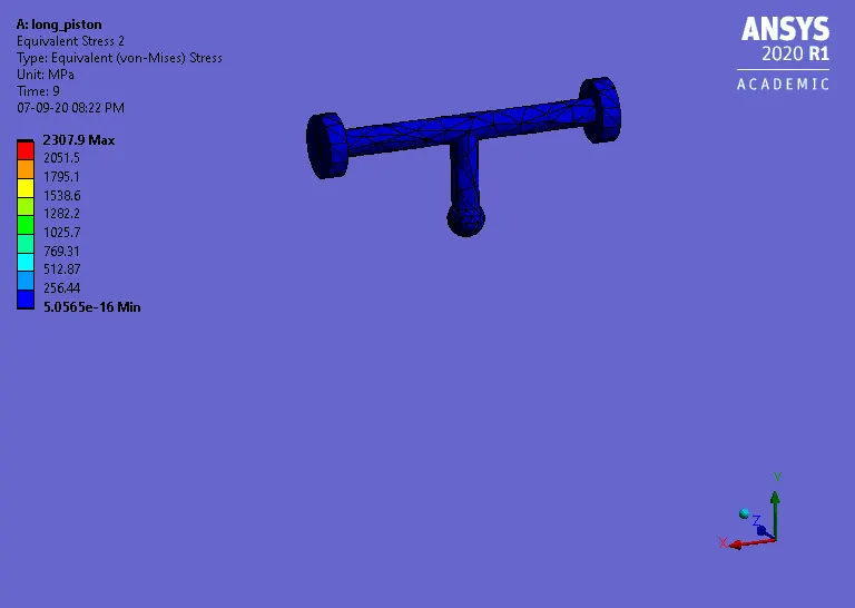
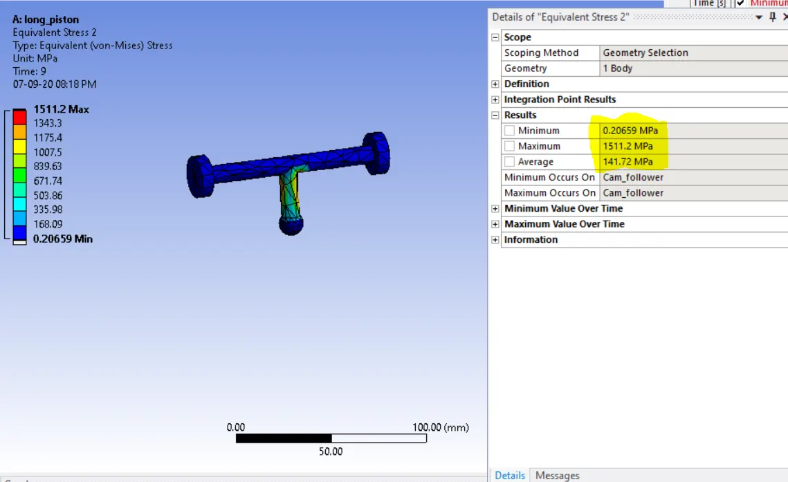
Equivalent stress on cam follower
Case2-Fricitional with 0.1 as the frictional contact
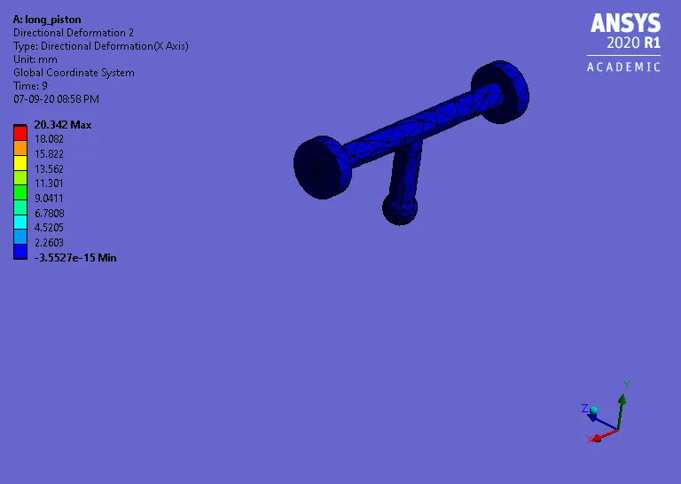
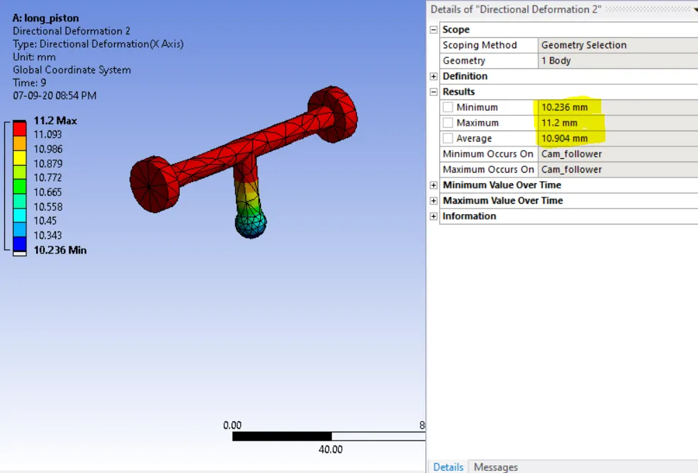
Directional Deformation x axis
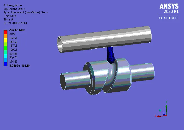
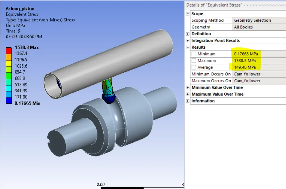
Equivalent stress
Equivalent elastic strain Max
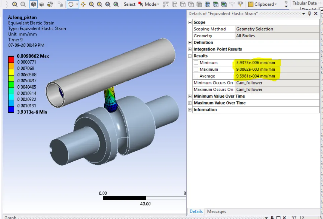
Equivalent stress on cam follower
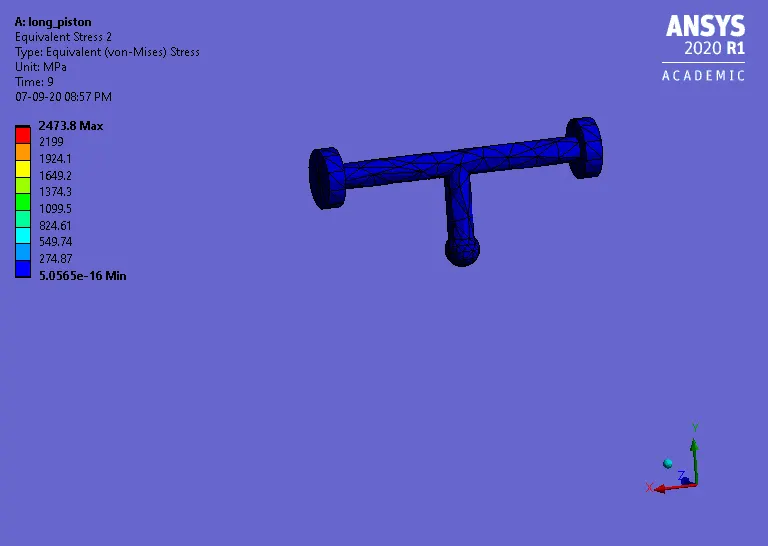
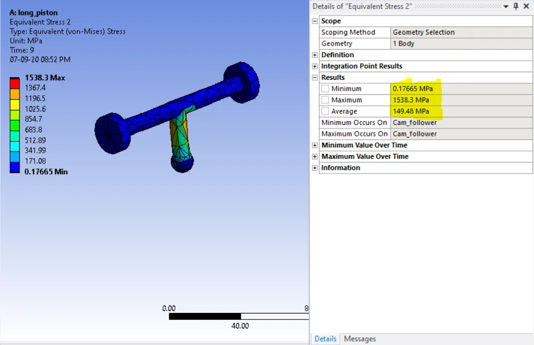
Case3-Fricitonal with 0.2 as the frictional contact
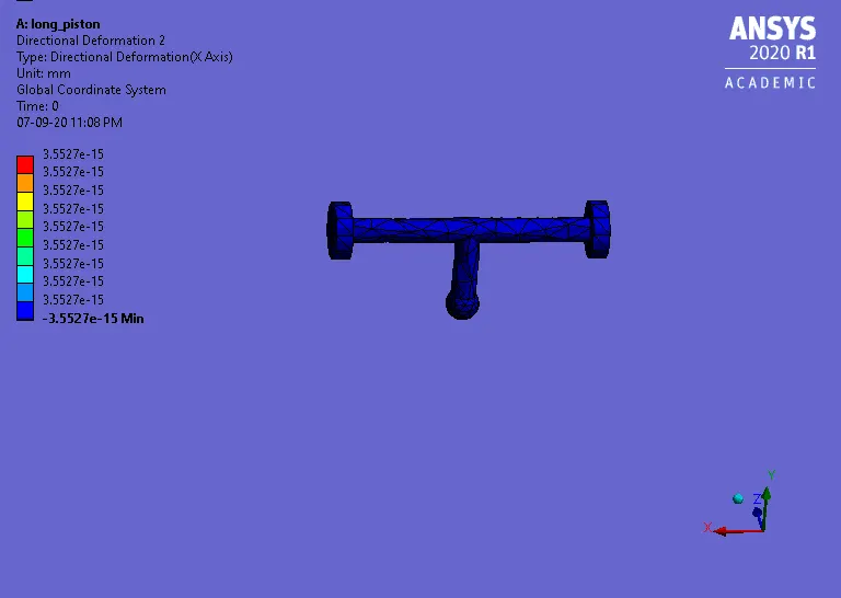
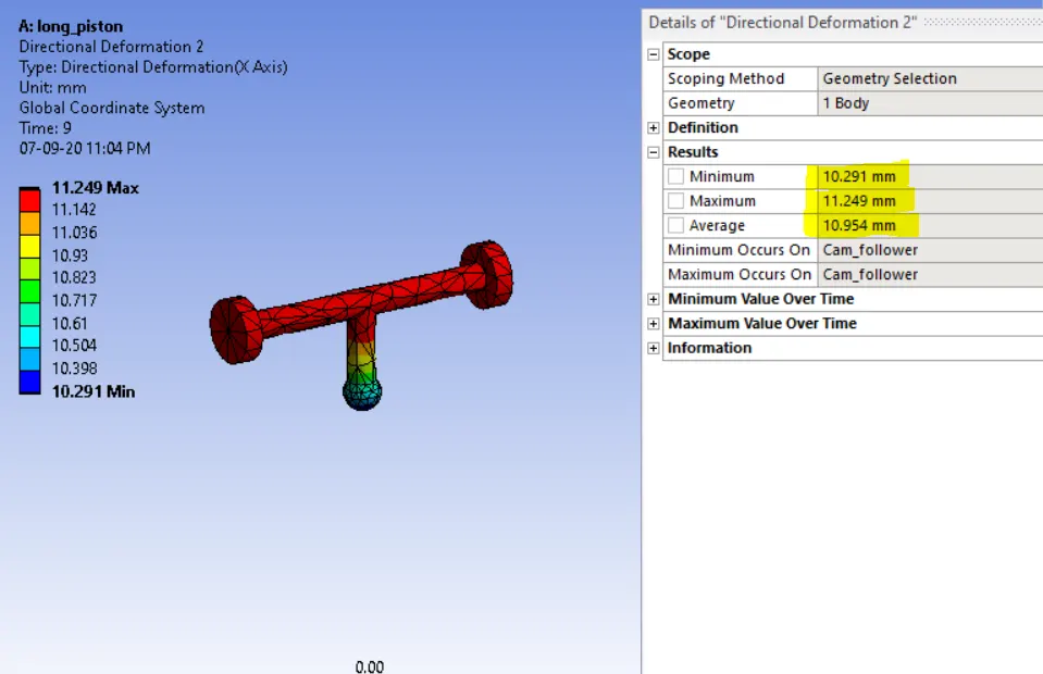
Directional Deformation a axis
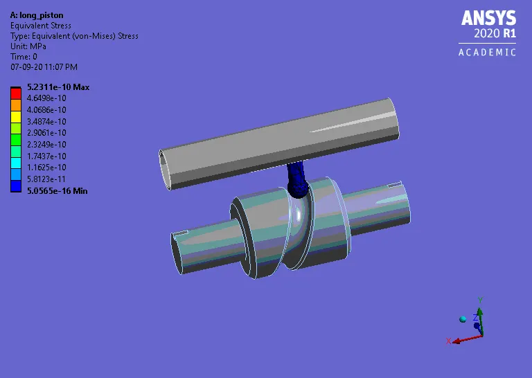
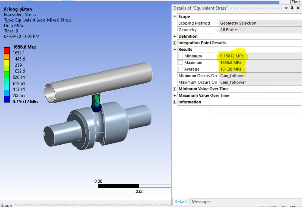
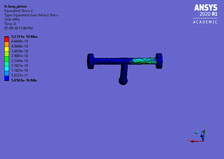
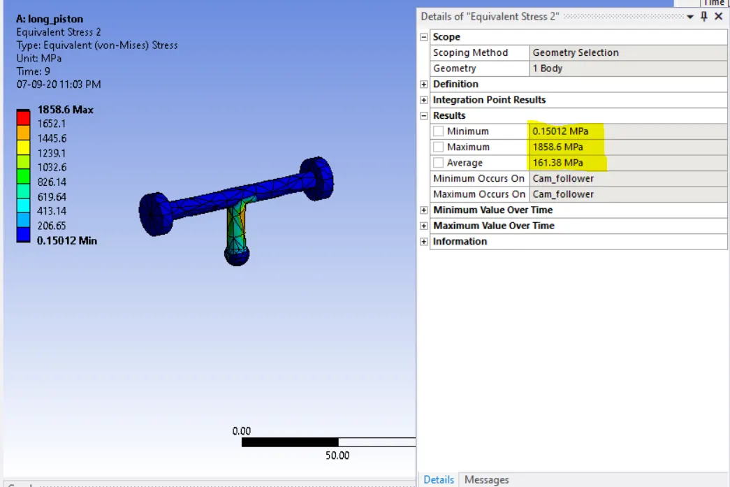
Equivalent stress
Equivalent elastic strain Max
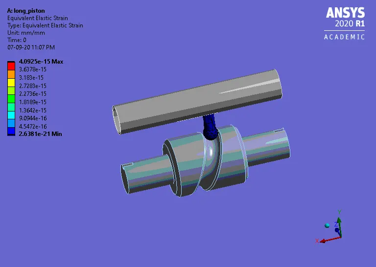
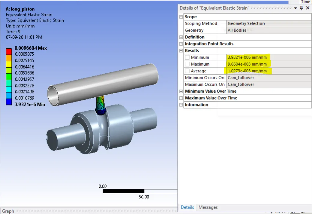
Equivalent stress on cam follower
| Directional Deformation on A Axis | Equvialent stress on Cam follower | Equivalent strain | |
|
Case1- Frictionless contact, |
11.2 mm | 1511.2 Mpa | 8.5611e-003 mm/mm |
|
Case2- Friction co-efficient 0.1 |
11.2 mm | 1538.3 Mpa | 9.0062e-003 mm/mm |
| Case3-Friction coefficient 0.2 | 11.249 mm | 1856.6 Mpa | 9.6604e-003 mm/mm |
Inference –
Equivalent stress- Stress keeps on increasing as we increase the friction coefficient value .As the frictional coefficient value increase it resists more the movement of the follower and the follower and thus the Stress develops at the stem of the follower
Directional Deformation- it is increasing slight with increasing friction coefficient value.
Equivalent Elastic strain- Also because of the same reason as equivalent stress, Equivalent strain also increases due to more resistance offered.