Photo Realistic Rendering
American chopper Report
Aim:- To design a photorealistic model of an American chopper bike in Solidworks using different tools and command then render the model.
OBJECTIVE:-
- Understand different tools and command in Solidworks software
- Modeling of an individual component using the commands
- Assembling the individuals component to complete the chopper
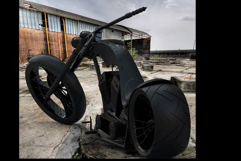
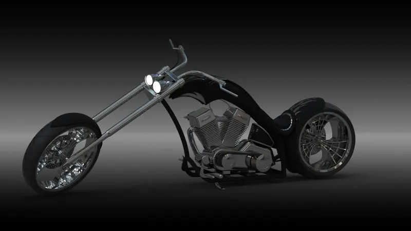
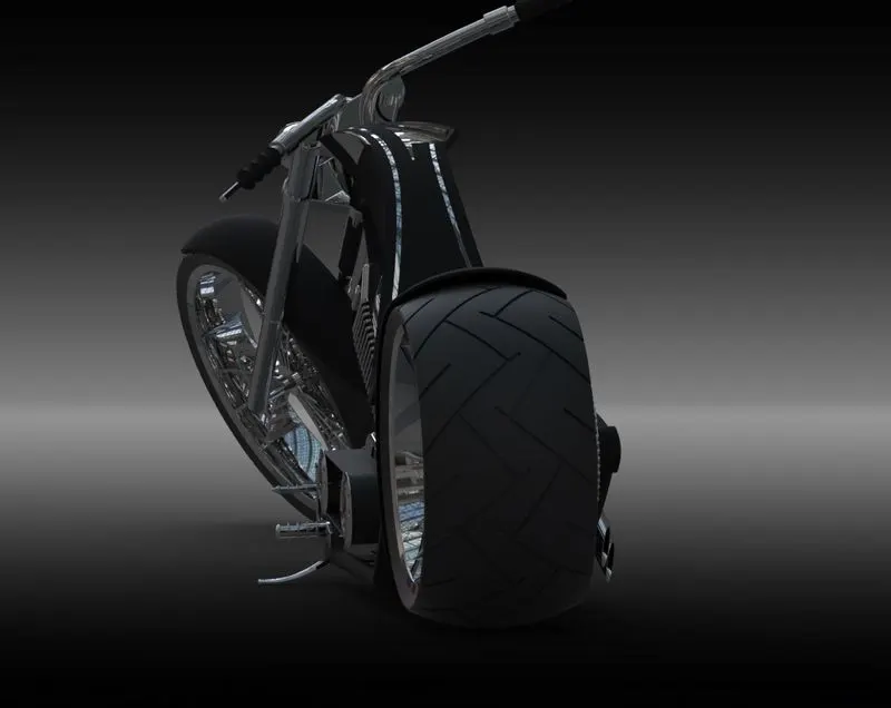
- Rendering the chopper using Photoview 360 and Visualize
FEATURES USED
The feature that is being used to model American chopper is as follows,
SOLID FEATURES:-
Sketch:-
The sketch is a two-dimensional representation of the model which is to be later converted into a three-dimensional model sketch that can be drawn using line, arc circle, rectangle, spline, etc on a plane
Extrude Boss/Base:-
It is used to convert a 2D sketch into a 3D solid body by extending the edge of the drawing to a certain distance and angle.
EXTRUDE CUT:-
it is used to remove/delete a certain area/space from a 3D solid model from a 2D sketch.
OFFset:-
It is used to replicate/copy(i.e offset) a 2d sketch to a certain distance on a plane or surface.
Lofted Boss/Base:-
It is used to generate a profile or make a 3D model of various size sketches which cannot be done through extrude boss/base
Split:-
It is used to project features (sketch, solid, surface, plane, etc..) to surface (curved or planar). We can split solid bodies too using this command.
Trim:-
It is used to remove (trim) unwanted 2D sketches from a plane or surface
Revolve:-
It is used to create a replica of 2D sketches by revolving it from a common axis around 360 degrees
Mirror:-
it is used to create a replica of 2D sketches, features, bodies to another half using a common reference like a plane, construction line, face, etc
Combine:-
It is used to join two or more solid surfaces into a single (unibody) solid model.
Chamfer:-
it is used to cut out a slope in an edge of the 3D model using distance and angle appropriately
Fillet:-
To create a rounded edge on both inner and outer ones using a radius value on the 3D model and 2D sketches.
Linear Pattern:-
it is used to create a different number of instances linearly using distance relation and angle relations.
Circular Pattern:-
It is used to create a different number of instances circularly using angle relation.
Swept Boss/Base:-
To create a 3D solid body using a 2D sketch and a reference geometry for the profile
SURFACE FEATURES:-
Extend Surface:-
To create a surface using a 2D sketch according to the distance needed.
Extend Surface:-
To increase (extend) the length of the surface already being created.
Filled Surface:-
To fill the surface using an edge where there the surface is not completely closed.
Surface Trim:-
To remove the unwanted surface from a surface or group of the surface.
Surface Knit:-
To join various surfaces into a single one, then use gap control to fill the edge and finally convert the surface model into a solid model.
Delete Face:-
It is used to remove a face of a model from the surface or plane,
PARTS IN AMERICAN CHOPPER:-
The various parts that are to be created using Solidworks are,
- Transmission Belt
- Kick Stand
- Front Fender
- Rear Fender
- Chain
- Oil Tank
- Pedal
- Front Wheel
- Rear Wheel
- Front Fork
- Chassis
- Engine
- Gas Tank
Transmission Belt:-
The transmission belt is used to transmit power from engine to gearbox, it is made up of high-Quality rubber.
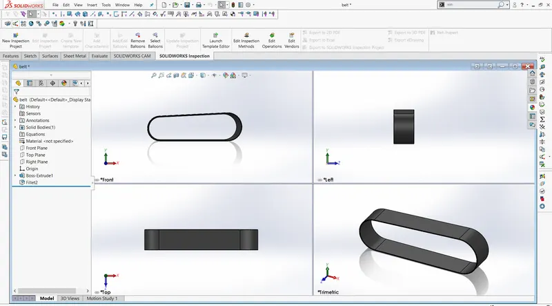
Feature Used,
- Boss Extrude
- Fillet
- Offset Entities
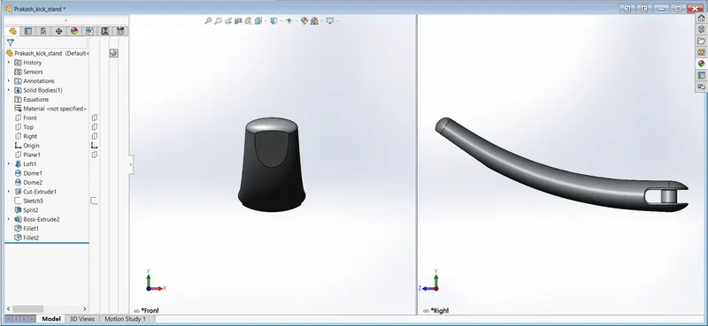
Kick Stand:-
It is used to balance the motorcycle to the ground against the gravitational force.
Front and Rear Fender:-
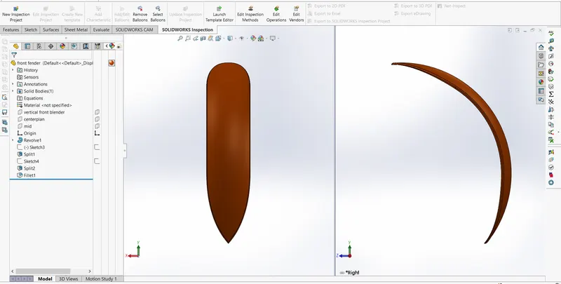
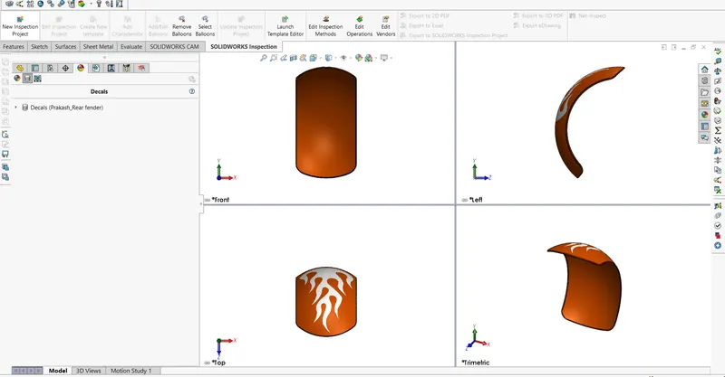
Fenders are used to prevent foreign entities long the direction of motion of the tires
Features Used,
- Boss Extrude
- Fillet
- Cut Extrude
- Dome
- Loft
Features Used,
- Revolved Boss
- Shell
- Split
- Fillet
Front Fender:-
Rear Fender:-
Chain:-
To transfer the mechanical (rotational) power from the gearbox to the wheels.
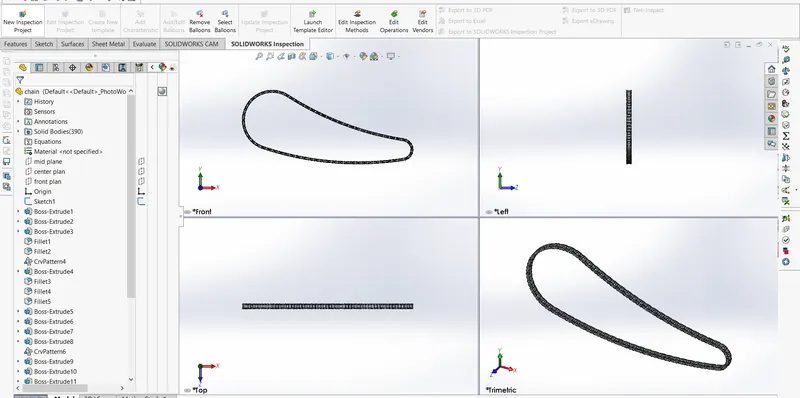
Features Used,
- Boss Extrude
- Fillet
- Projected Curve
- Pattern
- Mirror
Oil Tank:-
It is used to store Lubricant (oil) for cooling the interior of the engine
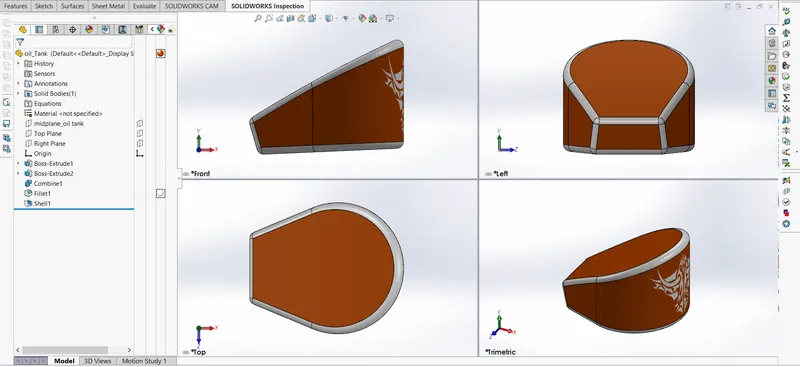
Features Used,
- Boss Extrude
- Fillet
- Shell
- Combine
Pedal:-
It is used to rest our foot and increase, reduce, or vice-versa of the gears accordingly
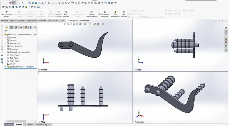
Features used,
- Boss Extrude
- Fillet
- Revolved Boss
- Chamfer
- Dome
- Spline
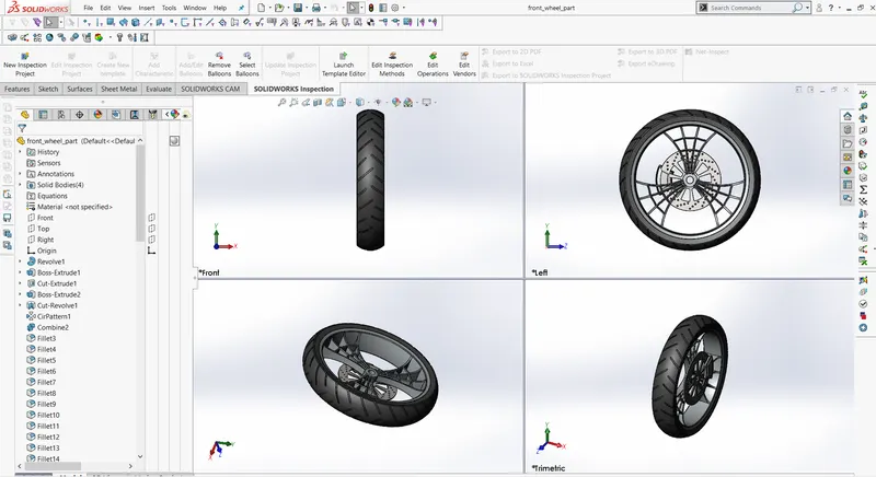
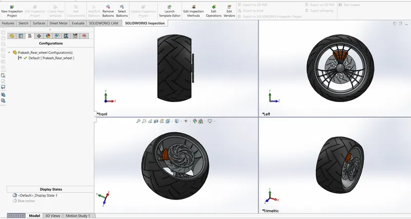
Front and Rear Wheel:-
It is used to move and steer using handles to change the directions while driving.
Features Used,
- Boss extrude
- Fillet
- Cut Extrude
- Revolved Cut
- Chamfer
- Circular Pattern
Front Wheel:-
Rear Wheel:-
Front Fork:-
It holds the front wheel and is also used to steer while driving the motorcycle.
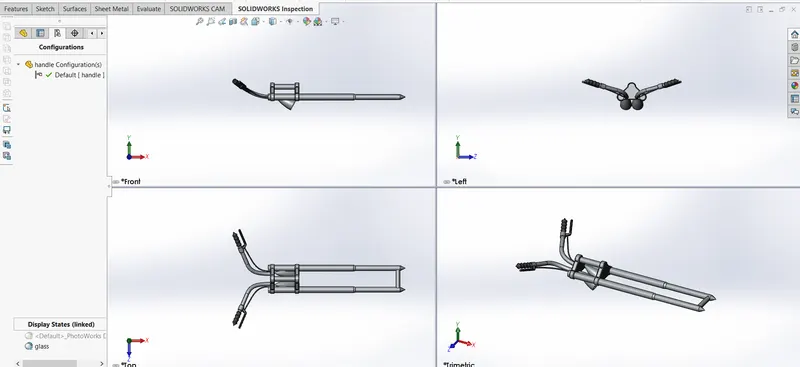
Features Used,
- Boss Extrude
- Fillet
- Cut Extrude
- Dome
- Swept boss
- Projected curve
- Mirror
- Combine
Chassis:-
It is used to hold down the engine and the main component in a motorcycle where all the electrical lines pass through.
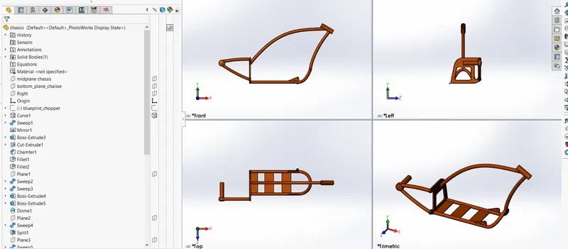
Features Used,
- Boss Extrude
- Fillet
- Cut Extrude
- Dome
- Swept Boss
- Project Curve
- Mirror
- Combine
- Extrude Cut
Engine:-
It is the main component in a motorcycle where the fuel is burnt and converted into mechanical energy (rotational motion) for propulsion.
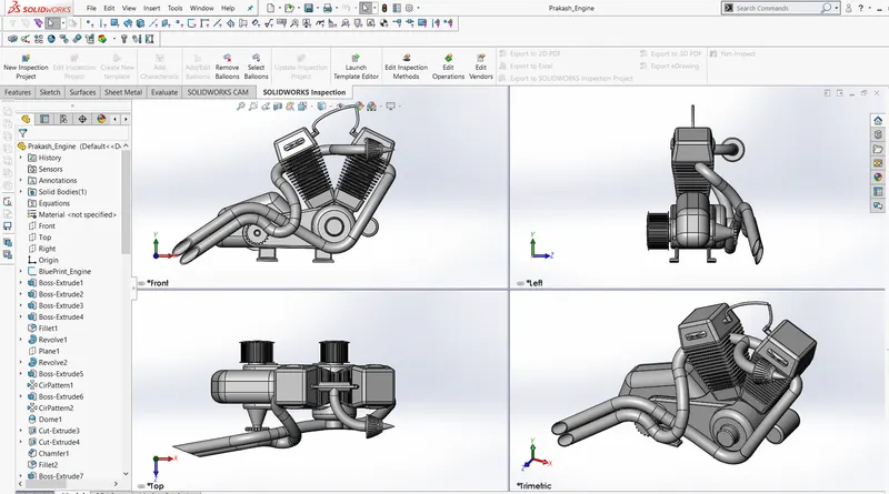
Features Used,
- Boss Extrude
- Fillet
- Cut Extrude
- Dome
- Swept boss
- Projected curve
- Mirror
- Combine
- Chamfer
- Linear Pattern
- Composite curve
- Circular Pattern
Gas Tank:-
It is used to store the fuel for propulsion and has an integrated seat for rider and passenger seating.
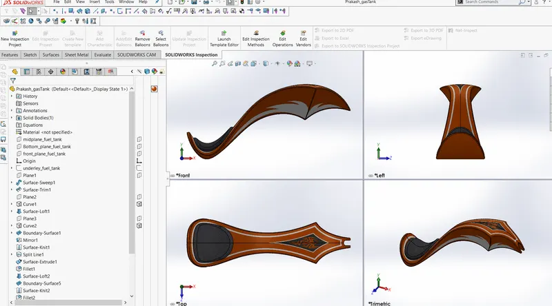
Features Used,
- Surface Loft
- Project curve
- Swept cut
- Surface knit
- Mirror
Final Assembly:-
The entire individual component is imported and integrated using different kinds of mating techniques.
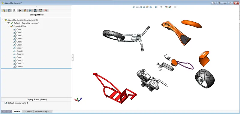
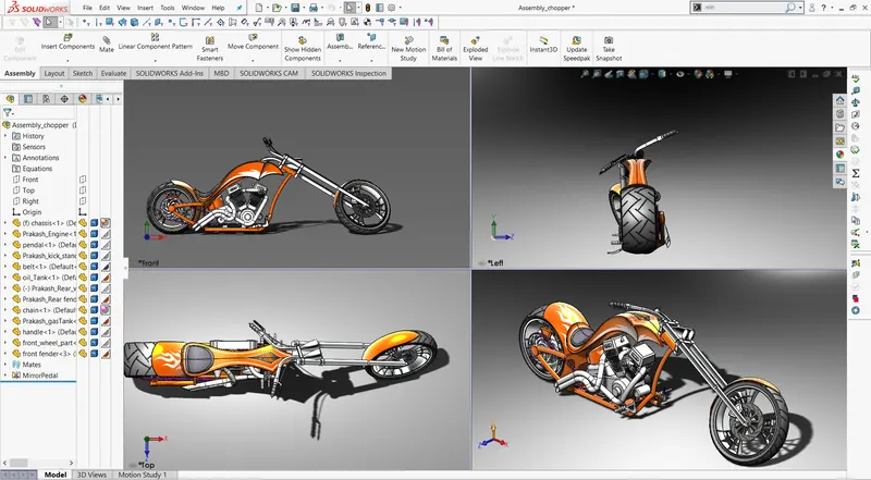
Photo view 360 Rendering:-
The cameras, light, Background, scenes, color are all set up and rendering has been done using Photo view 360 and inbuilt software in Solidworks.
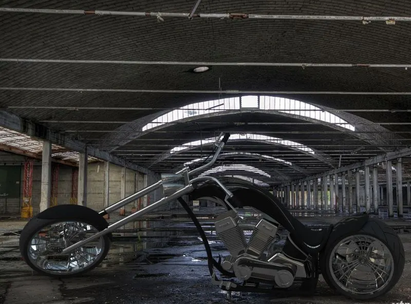
Visualize Rendering:-
For more accurate presentation the same rendering is done in Solid works Visualize software
Conclusions:-
From basis sketching to final rendering of American chopper was done using solid works software and also was able to learn various commands in solid works workbench